
Related Manuals for VIA Technologies P4XB-MA


Summary of Contents for VIA Technologies P4XB-MA
- Page 1 VIA Mainboard User’s Manual VIA P4XB-MA Harnessing the Power of DDR266 SDRAM ® ® for the Intel Pentium 4 Processor Version 1.0 December 5, 2001...
- Page 2 Copyright Copyright by VIA Technologies Inc. (“VIA”). No part of this manual may be reproduced or transmitted in any form without express written authorization from VIA. Trademarks All trademarks are the property of their respective holders. Data protection All data should be backed-up prior to the installation of any drive unit or storage peripheral.
- Page 3 FCC-B Radio Frequency Interference Statement This equipment has been tested and found to comply with the limits for a class B digital device, pursuant to part 15 of the FCC rules. These limits are designed to provide reasonable protection against harmful interference when the equip- ment is operated in a commercial environment.
-
Page 4: Copyright Notice
Copyright Notice We take every care in the preparation of this document, but no guarantee is given as to the correctness of its contents. Our products are under continual improvement and we reserve the right to make changes without notice. Trademarks All trademarks used in this manual are the property of their respective owners. -
Page 5: Safety Instructions
Safety Instructions NOTE Always read the safety instructions carefully. Keep this User’s Manual for future reference. Keep this equipment away from humidity. Lay this equipment on a reliable flat surface before setting it up. The openings on the enclosure are for air convection hence protects the equipment from overheating. -
Page 6: Box Contents
Box Contents • 1 x VIA Mainboard • 1 x User’s manual • 1 x Floppy ribbon cable • 1 x ATA-66/100 Hard drive ribbon cable • 1 x 2 Port USB Module • 1 x Driver Utilities CD... -
Page 7: Table Of Contents
CONTENTS Chapter 1. Specifications ................. 1-1 Mainboard Specifications ..............1-2 Mainboard Layout ................1-4 Chapter 2. Installation ................2-1 CPU ...................... 2-2 CPU Installation Procedure ............2-2 Installing the CPU Fan ..............2-3 CPU Core Speed Derivation Procedure ......... 2-4 Memory Installation ................ - Page 8 HDD LED ..................2-13 CD-In Connector: J2 ..............2-14 Aux Line-In Connector: J6 ............2-14 Modem-In Connector: J5 ............. 2-14 IrDA Infrared Module Connector: IR1 & IR2 ......2-15 Front Panel Audio Connector: JAUDIO1 ........2-16 Wake On Ring Connector: JMDM1 ..........2-17 Wake On LAN Connector: JWOL1 ..........
- Page 9 PC Health Status ................3-28 Frequency/Voltage Control ..............3-29 Load Fail-Safe Defaults ..............3-31 Load Optimized Defaults ..............3-32 Supervisor/User Password ..............3-33 Save & Exit Setup ................3-35 Exit Without Saving ................3-36 Chapter 4. Driver Setup ................4-1 VIA Apollo P4X266A Chipset Driver ...........
-
Page 10: Chapter 1. Specifications
Introduction Specifications The VIA P4XB-MA Micro ATX mainboard is a high per- formance mainboard based on VIA Apollo P4X266A chipset. The VIA Apollo P4X266A chipset brings sup- ® port for high bandwidth DDR266 SDRAM to the Intel ® Pentium 4 processor platform, and utilizes advanced V- Link technology for optimal system efficiency. -
Page 11: Mainboard Specifications
Chapter 1 Mainboard Specifications ® ® Supports 478-pin Intel Pentium 4 Processors 400MHz Front Side Bus. Supports clock speeds from 1.5GHz to 2.0GHz. Chipset VIA Apollo P4X266A chipset - 64bit DDR SDRAM memory interface (200/266MHz). - 32bit AGP interface (66MHz) for 4x/2x mode. - 8bit V-Link interface (66MHz) with peak bandwidth of 266MB/s. - Page 12 Introduction - 1 game (MIDI) port. - 3 Audio jacks: line-out, line-in and mic-in. Audio AC97 link controller integrated in VT8233. 2-channel RealTek ALC201A software audio codec . - Compliance with AC97 v2.2 spec. - Meets PC2001 audio performance requirement. RealTek RTL81000L 10/100 Base-T Fast Ethernet Controller.
-
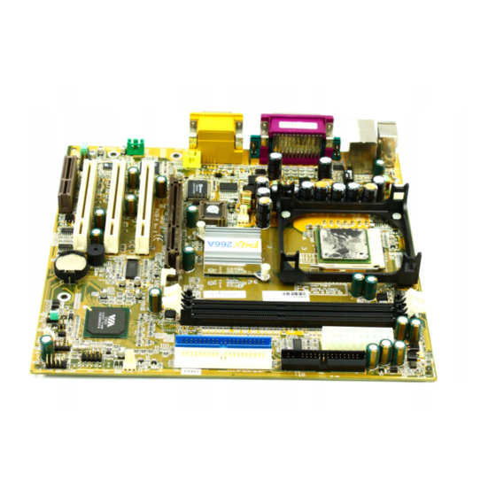
Page 13: Mainboard Layout
Chapter 1 Mainboard Layout VIA P4XB-MA MicroATX Mainboard... -
Page 14: Chapter 2. Installation
Hardware Setup Installation This chapter provides you with the information about hardware setup procedures. While installating, be careful in holding the components and follow the installation procedures. Some components can be damaged if they are installed incorrectly. If possible, use a grounded wrist strap before han- dling computer components. -
Page 15: Cpu
Chapter 2 Central Processing Unit: CPU ® ® The VIA P4XB-MA mainboard supports the Intel Pentium 4 processor in the 478 pin package. When installing the CPU, make sure the CPU has a heat sink and a cooling fan attached on the top to prevent overheating. If the heat sink and cooling fan are not included with the CPU, contact your dealer to purchase and install them before turning on the computer. -
Page 16: Installing The Cpu Fan
Hardware Setup Installing the CPU Fan To effectively dissipate heat generated by the CPU, you need to attach the CPU cooling fan and heatsink on top of the CPU. Follow the instructions below to install the Heatsink/Fan: Locate the CPU and its retention Position the heatsink onto the reten- mechanism on the motherboard. -
Page 17: Cpu Core Speed Derivation Procedure
Chapter 2 Connect the fan power cable from the mounted fan to the 3-pin fan power connector on the board. fan power cable CPU Core Speed Derivation Procedure CPU Clock 100MHz Core/Bus ratio then CPU core speed Host Clock x Core/Bus ratio 100MHz x 14 1.4GHz Overclocking... -
Page 18: Memory Installation
Hardware Setup Memory Installation The mainboard provides two 184-pin DDR DIMM (2.5V) with 4 memory banks. To operate properly, at least one DIMM module must be installed. You can install two PC1600/PC2100 DDR SDRAM modules on the DDR DIMM slots (DDR 1~2). DDR (Double Data Rate) SDRAM is similar to conventional SDRAM, but doubles the rate by transfering data twice per cycle. -
Page 19: Ddr Sdram Module Installation Procedures
Chapter 2 DDR Module Installation Procedures You can install either single sided or double sided 184-pin DDR DIMM modules into DDR DIMM slots, depending on your requirements. As op- posed to SDR DIMMs, DDR DIMMs have only one notch in the center of module. -
Page 20: Power Supply
Hardware Setup Power Supply The P4XB-MA mainboard requires an ATX power supply for powering the system. Before inserting the power supply connector, always make sure that all components are installed correctly to ensure that no damage will be caused. ATX 20-Pin Power Connector: JWR1 This connector is for the ATX power supply. -
Page 21: Back Panel
Chapter 2 Back Panel The Back Panel of the VIA P4XB-MA mainboard provides the following connectors: RJ-45 LAN Port PS/2 Mouse Joystick/MIDI LPT 1 COM A COM B PS/2 Keyboard Line In Line Out USB Port 1 USB Port 2... -
Page 22: Audio Port Connectors
Hardware Setup Audio Port Connectors Line Out is a connector for Speakers or Headphones. Line In is used for an external CD player, tape player, or other audio devices. Mic In is a connector for microphones. Parallel Port Connector: LPT1 The mainboard provides a 25-pin female centronic connector for LPT. -
Page 23: Connectors
Chapter 2 Connectors The P4XB-MA mainboard provides connectors for FDD, IDE HDD, case, modem, LAN, USB Ports, IR module and CPU/System FAN. Floppy Disk Drive Connector: FDD1 The standard floppy disk drive connector supports 360K, 720K, 1.2M, 1.44M and 2.88M floppy disk types. -
Page 24: Hard Disk Connectors: Ide1 & Ide2
Hardware Setup Hard Disk Connectors: IDE1 & IDE2 The mainboard has a 32-bit Enhanced PCI IDE and Ultra DMA 33/66/100 con- troller that provides PIO mode 0~4, Bus Master, and Ultra DMA/33/66/100 functions. You can connect up to four hard disk drives, CD-ROM, 120MB Floppy (reserved for future BIOS) and other devices. -
Page 25: Case Connector: Jfp2
Chapter 2 Case Connector: JFP2 The case connector JFP2 allows you to connect to the the Power Switch, Reset Switch, Power LED and HDD LED on the case. Power Reset Power Switch Switch Reserved 9 10 JFP2 JFP2 Pin Definition Description Description *HDD_LED+... -
Page 26: Hdd Led
Hardware Setup 2-pin single color power LED: The power LED is not able to change its color. Therefore, you can only choose Blinking in the BIOS utility for the power LED to indicate the suspend/sleep mode. 2-pin dual color power LED: The 2-pin power LED can change its color to indicate different system states. -
Page 27: Cd-In Connector: J2
Chapter 2 CD-In Connector: J2 This connector is for the CD-ROM audio connector. Aux Line-In Connector: J6 This connector is for a DVD add-on card with Line-in connector. Modem-In Connector: J5 This connector is for a modem with internal audio connector. Mono_Out Phone_In 2-14... -
Page 28: Irda Infrared Module Connector: Ir1 & Ir2
Hardware Setup IrDA Infrared Module Connectors: IR1 & IR2 These connectors allow you to connect to IrDA Infrared modules. You must configure the settings through the BIOS setup to use the IR function. The difference between IR1 & IR2 is that IR2 is compliant to the3 Intel Front Panel I/O Connectivity Design Guide. -
Page 29: Front Panel Audio Connector: Jaudio1
Chapter 2 Front Panel Audio Connector: JAUDIO1 You can connect an optional audio connector to the Front Panel Audio pin- header. Pin numbers 1 to 10 of the audio pin header are compliant to the Intel Front Panel I/O Connectivity Design Guide. JAUDIO1 JAUDIO1 Pin Definition (1~10) Signal... -
Page 30: Wake On Ring Connector: Jmdm1
Hardware Setup Wake On Ring Connector: JMDM1 This connector allows you to connect to a modem card with the Wake On Ring function. The connector will power up the system when a signal is received through the modem card. 5VSB MDM_WAKEUP JMDM1 Wake On LAN Connector: JWOL1... -
Page 31: Fan Power Connectors: Pfan1/Sfan1
Chapter 2 Fan Power Connectors: PFAN1/SFAN1 The PFAN1 (processor fan) & SFAN1 (system fan) connectors provide +12V power supply for the system cooling fan, via a three-pin connector. When connecting the wire to the connectors, always take note that the red wire is the positive and should be connected to the +12V, the black wire is Ground and should be connected to GND. -
Page 32: Usb Front Connector: Usb2 (Intel Spec)
Hardware Setup USB Front Connector: USB2 (Intel spec) The mainboard provides a front Universal Serial Bus (USB) connector for con- necting additional USB devices. This USB2 connector is compliant to the Intel Front Panel I/O Connectivity Design Guide. USB2 Pin Definition Description Description -DATA3... -
Page 33: Remote Power On/Off Switch Connector: Jrms1
Chapter 2 Remote Power On/Off Switch Connector: JRMS1 Connects to a 2-pin push button switch. When the system is off, pressing the button will turn the system on. When the system is on, pressing the button once will enter the system to the sleep/suspend state. If the button is pressed for more than four seconds, the system will be turned off. -
Page 34: Jumpers
Hardware Setup Jumpers The mainboard provides one jumper for setting the computer’s functions. This section will explain how to change your mainboard’s function through the use of the jumper. Clear CMOS Jumper: JBAT1 There is a CMOS RAM on board that has a power supply from external battery to keep the data of system configuration. -
Page 35: Slots
Chapter 2 Slots The mainboard provides three 32-bit Master PCI bus slots, one AGP slot and one CNR slot. AGP Slot PCI Slots CNR Slot AGP (Accelerated Graphics Port) Slot The AGP slot allows you to insert the AGP graphics card. AGP is an interface specification designed for the throughput demands of 3D graphics. -
Page 36: Pci Interrupt Request Routing
Hardware Setup PCI Interrupt Request Routing The IRQ, abbreviation of interrupt request line and pronounced I-R-Q, are hardware lines over which devices can send interrupt signals to the microprocessor. The “PCI & LAN” IRQ pins are typically connected to the PCI bus INT A# ~ INT D# pins as follows: Order 1 Order 2... - Page 37 BIOS Setup Chapter 3. BIOS Setup BIOS Setup Entering Setup Control Keys Getting Help The Main Menu Standard CMOS Features Advanced BIOS Features Advanced Chipset Features 3-11 Integrated Peripherals 3-16 Power Management Setup 3-22 PNP/PCI Configurations 3-26 PC Health Status 3-28 Frequency/Voltage Control 3-29...
-
Page 38: Entering Setup
Chapter 3 Entering Setup Power on the computer and the system will start POST (Power On Self Test) process. When the message below appears on the screen, press <DEL> key to enter Setup. Press DEL to enter SETUP If the message disappears before you respond and you still wish to enter Setup, restart the system by turning it OFF and On or pressing the RESET button. -
Page 39: Getting Help
BIOS Setup Getting Help After entering the Setup menu, the first menu you will see is the Main Menu. Main Menu The main menu lists the setup functions you can make changes to. You can use the control keys (hi ) to select the item. The on-line description of the high- lighted setup function is displayed at the bottom of the screen. -
Page 40: The Main Menu
Chapter 3 The Main Menu ® Once you enter Award BIOS CMOS Setup Utility, the Main Menu (Figure 1) will appear on the screen. The Main Menu allows you to select from twelve setup functions and two exit choices. Use arrow keys to select among the items and press <Enter>... - Page 41 BIOS Setup PC Health Status This entry shows your PC health status. Frequency/Voltage Control Use this menu to specify your settings for frequency/voltage control. Load Fail-Safe Defaults Use this menu to load factory default settings in the BIOS for stable system running Load Optimized Defaults Use this menu to load factory default settings into the BIOS for optimal and stable system operations.
-
Page 42: Standard Cmos Features
Chapter 3 Standard CMOS Features The items in Standard CMOS Features Menu are divided into 10 categories. Each category includes no, one or more than one setup items. Use the arrow keys to highlight the item and then use the <PgUp> or <PgDn> keys to select the value you want in each item. - Page 43 BIOS Setup ing items. Enter the information directly from the keyboard. This information should be provided in the documentation from your hard disk vendor or the system manufacturer. If the controller of HDD interface is SCSI, the selection shall be “None”. If the controller of HDD interface is CD-ROM, the selection shall be “None”.
-
Page 44: Advanced Bios Features
Chapter 3 Advanced BIOS Features Anti-Virus Protection The item is to set the Virus Warning feature for IDE Hard Disk boot sector protection. If the function is enabled and any attempt to write data into this area is made, BIOS will display a warning message on screen and beep. Settings: Disabled and Enabled. - Page 45 BIOS Setup to load the disk operating system. The settings are: Floppy The system will boot from floppy drive. LS120 The system will boot from LS-120 drive. HDD-0 The system will boot from the first HDD. SCSI The system will boot from the SCSI. CDROM The system will boot from the CD-ROM.
- Page 46 Chapter 3 Typematic Rate Setting This item is used to enable or disable the typematic rate setting including Typematic Rate & Typematic Delay. Typematic Rate (Chars/Sec) After Typematic Rate Setting is enabled, this item allows you to set the rate (characters/second) at which the keys are accelerated.
-
Page 47: Advanced Chipset Features
BIOS Setup Advanced Chipset Features The Advanced Chipset Features setup option is used to change the values of the chipset registers. These registers control most of the system options in the computer. Note: Change these settings only if you are familiar with the chipset. DRAM Clock/Drive Control Press <Enter>... - Page 48 Chapter 3 the contents of the SPD (Serial Presence Detect) EPROM on the DRAM module. Selecting Yes makes SDRAM Cycle Length and Bank Interleave automatically determined by BIOS according to the configurations on the SPD. Setting options: Yes, No. DRAM Frequency (MHz) The chipset supports synchronous and asynchronous mode between host clock and DRAM clock frequency.
- Page 49 BIOS Setup RAS to CAS When DRAM is refreshed, both rows and columns are addressed separately. This setup item allows you to determine the timing of the transition from RAS (row address strobe) to CAS (column address strobe). The lower the timing numbers, the faster the memory performance. Set- ting options: 3T, 2T, Auto.
- Page 50 Chapter 3 address range dedicated to graphics memory address space. Host cycles that hit the aperture range are forwarded to the AGP without any translation. Setting options: 4MB, 8MB, 16MB, 32MB, 64MB, 128MB, and 256MB. AGP Driving Control The setting is used to adjust AGP driving force. Selecting Manual allows you to type a AGP driving force in AGP Driving Value.
- Page 51 BIOS Setup receive more data. Setting options: Enabled, Disabled. PCI Master 0 WS Write When Enabled, writes to the PCI bus are executed with zero wait state. Setting options: Enabled, Disabled. PCI Delay Transaction The chipset has an embedded 32-bit posted write buffer to support delay transaction cycles.
-
Page 52: Integrated Peripherals
Chapter 3 Integrated Peripherals Onboard LAN Chip This setting enables the onboard RTL8100L LAN chip. Setting options: Enabled, Disabled. VIA OnChip IDE Device Press <Enter> to enter the sub-menu and the following screen appears: 3-16... - Page 53 BIOS Setup OnChip IDE Channel 0/1 The integrated peripheral controller contains an IDE interface with sup- port for two IDE channels. Choose Enabled to activate each channel separately. Setting options: Disabled, Enabled. Primary/Secondary Master/Slave PIO The four fields allow you to set a PIO (Programmed Input/Output) mode for each of the four IDE devices that the onboard IDE interface supports.
- Page 54 Chapter 3 VIA OnChip PCI Device Press <Enter> to enter the sub-menu and the following screen appears: VIA-3058 AC97 Audio Auto allows the mainboard to detect whether an audio device is used. If the device is detected, the onboard VIA AC’97 (Audio Codec’97) con- troller will be enabled;...
- Page 55 BIOS Setup Winbond Super I/O Device Press <enter> to enter the sub-menu and the following screen appears: Onboard FDC Controller This setting enables or disables the onboard Floppy controller. Select Enabled when you have installed a floppy disk drive and want to use it. Onboard Serial Port 1/2 This setting specifies the base I/O port address and IRQ for the onboard Serial Port A / Serial Port B.
- Page 56 Chapter 3 ripheral in use. Setting options: Hi/Hi, Hi/Lo, Lo/Hi, Lo/Lo. IR Transmission Delay This setting determines whether the IR transmission rate will be delayed while converting to receiving mode. Setting options: Disabled, Enabled. UR2 Duplex Mode This setting controls the operating mode of IR transmission/reception. Setting options: Full, Half.
- Page 57 BIOS Setup EPP 1.7 spec or EPP 1.9 spec can be selected. ECP Mode Use DMA The ECP mode has to use the DMA channel, so choose the onboard parallel port with the ECP feature. After selecting it, the following mes- sage will appear: “ECP Mode Use DMA.”...
-
Page 58: Power Management Setup
Chapter 3 Power Management Setup The Power Management Setup allows you to configure you system to most effectively save energy while operating in a manner consistent with your own style of computer use. ACPI Function This item is to activate the ACPI (Advanced Configuration and Power Man- agement Interface) Function. - Page 59 BIOS Setup Power Management Option This item is used to select the degree (or type) of power saving and is related to these modes: Suspend Mode and HDD Power Down. There are three op- tions for power management: Min Saving Minimum Power Management. Suspend Mode = 1 Hour, and HDD Power Down = 15 Min.
- Page 60 Chapter 3 Delay 4 Sec. When you press the power button, the computer en- ters the suspend/sleep mode, but if the button is pressed for more than four seconds, the computer is turned off. Power/Sleep LED This setting determines how Power LED on the case indicates the sleep state. Settings are: Single LED The Power LED blinks to indicate the sleep state.
- Page 61 BIOS Setup Date (of Month) The field specifies the date for RTC Alarm Resume. Settings: 0~31. Resume Time (hh:mm:ss) The field specifies the time for RTC Alarm Resume. Format is <hour> <minute><second>. IRQs Activity Monitoring Press Enter to enter the sub-menu and the following screen appears: Primary INTR Selecting ON will cause the system to wake up from power saving modes if activity is detected from any enabled IRQ channels.
-
Page 62: Pnp/Pci Configurations
Chapter 3 PNP/PCI Configurations This section describes configuring the PCI bus system. PCI, or Personal Com- puter Interconnect, is a system which allows I/O devices to operate at speeds nearing the speed the CPU itself uses when communicating with its own spe- cial components. - Page 63 BIOS Setup system such as Windows 95/98. If you set this field to “manual” choose spe- cific resources by going into each of the sub menu that follows this field (a sub menu is preceded by a “ ”). The settings are: Auto (ESCD), Manual. IRQ Resources The items are adjustable only when Resources Controlled By is set to Manual.
-
Page 64: Pc Health Status
Chapter 3 PC Health Status This section displays the settings for monitoring the status of your CPU, fans, and overall system status. CPU Warning Temperature If the CPU temperature reaches the upper limit preset in this setting, the warn- ing mechanism will be activated. This helps you to prevent the CPU overheat problem. -
Page 65: Frequency/Voltage Control
BIOS Setup Frequency/Voltage Control Auto Detect DIMM/PCI Clk To reduce the occurrence of electromagnetic interference (EMI), the BIOS de- tects the presence or absence of components in DIMM and PCI slots and turns off system clock generator pulses to empty slots. The settings are: Ena- bled, Disabled. - Page 66 Chapter 3 CPU Ratio This setting controls the multiplier that is used to determine the internal clock speed of the processor relative to the external or motherboard clock speed. 3-30...
-
Page 67: Load Fail-Safe Defaults
BIOS Setup Load Fail-Safe Defaults This option allows users to restore all the BIOS settings to the default Fail-Safe values. The Fail-Safe default settings are the settings set by the mainboard manufacturer for stable running of the mainboard. Pressing ‘Y’ loads the default Fail-Safe settings for stable system performance. 3-31... -
Page 68: Load Optimized Defaults
Chapter 3 Load Optimized Defaults This option on the main menu allows users to restore all the BIOS settings to the default Optimized values. The Optimized Defaults are the default values also set by the mainboard manufacturer for both optimized and stable perform- ance of the mainboard. -
Page 69: Supervisor/User Password
BIOS Setup Set Supervisor/User Password When you select this function, a message as below will appear on the screen: Type the password, up to eight characters in length, and press <Enter>. The password typed now will clear any previously set password from CMOS memory. - Page 70 Chapter 3 entry to Setup. If set to Setup, password prompt only occurs when trying to enter Setup. About Supervisor Password & User Password: Supervisor password : Can enter and change the settings of the setup menus. User password: Can only enter but do not have the right to change the settings of the setup menus.
-
Page 71: Save & Exit Setup
BIOS Setup Save & Exit Setup When you want to quit the Setup menu, you can select this option to save the changes and quit. A message as below will appear on the screen: Typing “Y” will allow you to quit the Setup Utility and save the user setup changes to RTC CMOS. -
Page 72: Exit Without Saving
Chapter 3 Exit Without Saving When you want to quit the Setup menu, you can select this option to abandon the changes. A message as below will appear on the screen: Typing “Y” will allow you to quit the Setup Utility without saving any changes to RTC CMOS. -
Page 73: Chapter 4. Driver Setup
Driver Setup Chapter 4. Driver Setup Driver Setup This chapter gives you detailed instructions on instal- lation & setup of VIA chipset & Realtek ALC201A audio drivers. It consists of the following topics: VIA Apollo P4X266A Chipset Drivers Realtek ALC201A Audio Driver Note: You must install VIA chipset drivers first before installing other drivers like audio or VGA drivers. -
Page 74: Via Apollo P4X266A Chipset Driver
Chapter 4 VIA Apollo P4X266A Chipset Drivers The VIA P4X266A chipset provides superior performance between the CPU, DRAM, V-Link bus and AGP 8x graphics controller bus with pipelined, burst and concurrent operation. With a highly integrated PCI/LPC controller, its internal bus structure is based on 66MHz PCI bus that provides 2x bandwidth compared to previous generation PCI/ISA bridge chips. - Page 75 Driver Setup ® Driver Installation for Windows 98SE 1. Insert the supplied CD disk into the CD-ROM drive. 2. The CD will auto-run and the setup screen will appear. 3. Click on VIA Chipset Drivers and the screen will show VIA Service Pack 4.XX.
- Page 76 Chapter 4 ® Driver Installation for Windows 2000 Note: Before installing VIA chipset driver, you should installing Win- dows 2000 Service Pack2 or the latest version. 1. Insert the supplied CD disk into the CD-ROM drive. 2. The CD will auto-run and the setup screen will appear. 3.
- Page 77 Driver Setup ® Driver Installation for Windows 1. Insert the supplied CD disk into the CD-ROM drive. 2. The CD will auto-run and the setup screen will appear. 3. Click on Via Chipset Drivers and the screen will show VIA Service Pack 4.XX.
- Page 78 Chapter 4 ® Driver Installation for Windows NT4.0 ® NOTE: Install Windows NT4.0 Service Pack 6 or above before install- ® ing the VIA drivers into Windows 1. Insert the provided CD disk into the CD-ROM drive. 2. The CD will auto-run and the setup screen will appear. 3.
-
Page 79: Realtek Alc201A Audio Driver
Driver Setup Realtek ALC201A Audio Driver The ALC201A is an 18-bit, full duplex AC'97 2.2 compatible stereo audio CODEC designed for PC multimedia systems, including host/soft audio and AMR/ CNR based designs. ALC201A AC'97 CODEC incorporates proprietary con- verter technology to achieve high SNR greater than 90 dB. In addition, it sup- ports multiple CODEC extension with independent variable sampling rate and built-in 3D effects. - Page 80 Chapter 4 ® Driver Installation for Windows 98/ME/2000/NT4.0 1. Insert the provided CD_ROM disk into the CD-ROM drive. 2. The CD will auto-run and the setup screen will appear. 3. Click on ADVANCED Sound Drivers and follow the on-screen instruc- tions to complete the installation.
Need help?
Do you have a question about the P4XB-MA and is the answer not in the manual?
Questions and answers