
Related Manuals for VIA Technologies P4MA PRO


Summary of Contents for VIA Technologies P4MA PRO
- Page 1 VIA Mainboard User’s Manual VIA P4MA PRO Version 1.0 - August 16th, 2002 P/ N 9 9 - 5 1 -0108 1 1...
- Page 2 Copyright Copyright by VIA Technologies Inc. (“VIA”). No part of this manual may be reproduced or transmitted in any form without express written authorization from VIA. Trademarks All trademarks are the property of their respective holders. Data protection All data should be backed-up prior to the installation of any drive unit or storage peripheral.
- Page 3 FCC-B Radio Frequency Interference Statement This equipment has been tested and found to comply with the limits for a class B digital device, pursuant to part 15 of the FCC rules. These limits are designed to provide reasonable protection against harmful interference when the equip- ment is operated in a commercial environment.
- Page 4 TRADEMARKS All trademarks used in this manual are the property of their respective owners. Intel and Pentium are registered trademarks of Intel Corporation. PS/2 and OS/2 are registered trademarks of IBM Corporation. Windows 95/98/98SE/ME/2000/XP and Windows NT are registered trademarks of Microsoft.
-
Page 5: Box Contents
Box Contents • 1 x VIA Mainboard • 1 x User’s manual • 1 x Floppy ribbon cable • 1 x ATA-66/100/133 IDE ribbon cable • 1 x 2 Port USB 2.0 Module • 1 x Driver Utilities CD... -
Page 6: Table Of Contents
Contents Specifications ............1-1 Mainboard Specifications ..........1-2 Mainboard Layout ............1-4 Connectors Guide ............. 1-5 Installation ............2-1 CPU Installation ..............2-2 CPU Installation ............... 2-2 CPU Core Speed .............. 2-3 CPU Fan Installation ............2-3 Memory Installation............2-5 DDR Module Installation .......... - Page 7 Digital Audio Connector: SPDIF ........2-16 Chassis Intrusion Connector: CI ........2-16 USB pin-header: USB3/4 ..........2-17 Wake-On LAN Connector: WOL ........2-17 Wake-On Ring Connector: WOR........2-18 Jumpers ................2-19 Clear CMOS Jumper: CLEAR_CMOS ......2-19 Audio Codec Auto Detect Jumper: OB_CODEC ..2-20 Slots ................
- Page 8 Software Setup ............. 4-1 Driver Utilities CD Content ..........4-2 Getting Started ............4-2 Running the Driver Utilities CD ......4-2 CD Content ..............4-2 viii...
-
Page 9: Specifications
Specifications Specifications The VIA P4MA PRO mainboard is based around the VIA ProSavageDDR P4M266 chipset, which brings support for high-performance DDR266 SDRAM to the Intel Pentium 4 platform. It is a high performance, ® ® cost-effective and energy efficient SMA chipset for the desktop PC. -
Page 10: Mainboard Specifications
Chapter 1 Mainboard Specifications • Supports Intel Pentium 4 Willamette/Northwood and Celeron processors ® ® ® in the 478 pin package • Supports 1.6GHz, 1.7GHz, 1.8GHz, 1.9GHz, 2GHz, 2.2GHz and upwards Chipset • VIA P4M266/VT8235 chipset - Supports Intel Pentium 4 and Celeron processors with 400MHz ®... - Page 11 Specifications Onboard I/O Connectors • 1 USB connector for 2 additional USB 2.0 ports • SPDIF ( optical & coaxial ) connector • Front-panel audio connectors ( Mic and Line Out ) • CD Audio-in connector • FIR connector • Wake-on-LAN, Wake-on-Ring •...
-
Page 12: Mainboard Layout
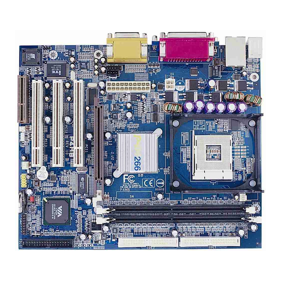
Bottom: USB ports Top: Parallel port AUX12V Bottom: COM 1/VGA out ATXPWR Top: Game port Bottom: Line-Out SPDIF Line-In AGP Slot PCI Slot 1 PCI Slot 2 OB_Codec PCI Slot 3 CLEAR_CMOS USB 3/4 F_PANEL SYSFAN VIA P4MA PRO Mainboard... -
Page 13: Connectors Guide
Specifications Connectors Guide Connectors Function Reference ATXPWR ATA 20-pin power connector see p. 2-7 ATX12V ATA 12 V power connector see p. 2-7 JM S1 Mouse connector see p. 2-8 JKB1 Keyboard connector see p. 2-8 USB Port Connectors Connecting to USB devices see p. -
Page 14: Installation
Installation Installation This chapter provides you with information about hardware setup procedures. While installing the mainboard, carefully hold the components and closely follow the installation procedures. Some components may be damaged if they are installed incorrectly. It is recommended to use a grounded wrist strap before handling computer components. -
Page 15: Cpu Installation
Chapter 2 CPU Installation ® ® The VIA P4MA PRO mainboard supports the Intel Pentium 4 Willamette/ ® Northwood and Celeron processors in the 478 pin package (PGA478). When installing the CPU, ensure the CPU has a large-size heatsink and a cooling fan attached on the top to prevent overheating. -
Page 16: Cpu Core Speed
Installation CPU Core Speed CPU Clock 100MHz Core/Bus ratio then CPU core speed CPU Clock x Core/Bus ratio 100MHz x 18 1.8GHz Overclocking This mainboard is designed to support overclocking. However, please make sure your components are able to tolerate such abnor- WARNING! mal settings, before overclocking. - Page 17 Chapter 2 3. Mount the fan on top of the heatsink. Press down the fan firmly until its four clips become wedged in the holes of the retention mechanism. 4. Press the two levers down to secure the fan. Each lever can be pressed down in only ONE direction.
-
Page 18: Memory Installation
Installation Memory Installation The VIA P4MA PRO mainboard provides 2 sockets for 184-pin, 2.5V DDR DIMM modules with 4 memory banks. To operate properly, at least one DIMM module must be installed. You can install PC1600/PC2100 DDR SDRAM modules on the DDR DIMM slots (DDR 1~2). -
Page 19: Ddr Module Installation
Chapter 2 DDR Module Installation You can install either single sided or double sided 184-pin DDR DIMM mod- ules into the DDR DIMM slot, depending on your requirements. Differing from SDR DIMM, DDR DIMM modules have only one notch on the center of the module. -
Page 20: Power Supply
Installation Power Supply The VIA P4MA PRO mainboard requires an ATX power supply for powering the system. Before inserting the power supply connector, always make sure that all components are installed properly to ensure that no damage will be caused. -
Page 21: Back Panel
COM 1 VGA out Mouse Connector: JMS1 Keyboard Connector: JKB1 The VIA P4MA PRO mainboard pro- The mainboard provides a standard PS/ vides a standard PS/2 mouse connec- 2 keyboard connector for attaching a tor for attaching a PS/2 mouse. You PS/2 keyboard. -
Page 22: Usb Port Connectors
Installation USB Port Connectors The VIA P4MA PRO mainboard provides 2 USB 2.0 ports (plus 1 pin-headers for up to 2 additional USB 2.0 connections; see 2-17). USB-compatible devices can be plugged directly into these ports. Pin Definition 5 6 7 8... -
Page 23: Serial Port Connector: Com 1
Chapter 2 Serial Port Connectors: COM 1 The mainboard offers one 9-pin male Serial Port connector (COM 1) . You can attach a serial mouse or other serial devices directly to this port. Pin Definition 1 2 3 4 5 SIGNAL DESCRIPTION Data Carry Detect... -
Page 24: Connectors
Installation Connectors Floppy Disk Drive Connector: FDD The standard floppy disk drive connector supports 360K, 720K, 1.2M, 1. 44M, and 2.88M. IrDA Infrared Module Connector: IR This connector allows you to connect an IrDA Infrared module. You must configure the setting through the BIOS setup to activate the IR function. Pin Definition SIGNAL CIRRX... - Page 25 Chapter 2 Front Panel Audio Connector: F_AUDIO This connector allows you to connect audio jacks on front panel for conve- nient connection and control of audio devices. Pin Definition SIGNAL MIC_IN2 GND_AUD MIC_VCC +5VCODEC LINEOUTR_AP LINEOUTR LINEOUTL_AP LINEOUTL F_AUDIO CD-In Connector: CD_IN This connector is for the CD-ROM audio connector.
-
Page 26: Hard Disk Connectors: Ide1 & Ide2
Installation Hard Disk Connectors: IDE1 & IDE2 The VIA P4MA PRO mainboard has a 32-bit Enhanced PCI IDE and Ultra DMA 33/66/100/133 controller that provides PIO mode 0~4, Bus Master, and Ultra DMA 33/66/100/133 functions. You can connect up to four hard disk drive, CD- ROM, LS-120 and other devices. -
Page 27: Fan Power Connectors: Cpu/Sys Fan
Chapter 2 Fan Power Connectors: CPU/SYS FAN The CPUFAN (CPU fan) and SYSFAN (system fan) run on +12V and maintain system cooling. When connecting the wire to the connectors, always be aware that the red wire is the Positive and should be connected to the +12V. The black wire is Ground and should be connected to GND. - Page 28 Installation Pin Definition SIGNAL SIGNAL PWR_LED+ HD_LED+ PWR_LED+ HD_LED- PWR_LED- SPEAKER- RESET+ RESET- SPEAKER- SLED+ SLED- F_PANEL Power Button (PW_BN) Connect to a 2-pin switch button. Pressing this button will turn the system power on or off. Reset Switch (RST_SW) The Reset Switch is used to reboot the system rather than turning the power ON/OFF.
-
Page 29: Digital Audio Connector: Spdif
Chapter 2 Digital Audio Connector: SPDIF The SPDIF output provides digital audio to external speakers or compressed AC3 data to an external Dolby Digital Decoder. Please make sure the SPDIF module is CORRECTLY plugged onto the connector. Incorrect orientation may cause permanent damage to the module. -
Page 30: Usb Pin-Header: Usb3/4
Installation USB pin-header: USB3/4 The mainboard provides 1 front USB pin-header connector, allowing up to 2 additional USB ports. Please plug the USB 2-port module onto this pin-header. USB 3/4 Pin Definition SIGNAL SIGNAL USB0- USB1- USB0+ USB1+ USB 3/4 Wake-On LAN Connector: WOL This connector allows you to connect a network card with the Wake-On LAN function. -
Page 31: Wake-On Ring Connector: Wor
Chapter 2 Wake-On Ring Connector: WOR This connector allows you to connect a modem card with the Wake-On Ring function. The connector will power up the system when a signal is received through the modem card. 2-18... -
Page 32: Jumpers
Installation Jumpers The VIA P4MA PRO mainboard provides jumpers for setting the mainboard’s functions. This section will explain how to change settings for your mainboard’s functions through the use of the jumpers. Clear CMOS Jumper: CLEAR_CMOS The onboard CMOS RAM stores system configuration data and has an onboard battery power supply. -
Page 33: Audio Codec Auto Detect Jumper: Ob_Codec
Chapter 2 Audio Codec Auto Detect Jumper: OB_CODEC This jumper enables or disables the audio codec auto detect function. If a CNR card based audio codec is found, then the auto detect function will automati- cally disable the onboard audio codec to avoid conflict. If the auto detect function is disabled, then the mainboard will always disable the onboard audio codec. -
Page 34: Slots
Installation Slots The mainboard provides three 32-bit Master PCI bus slots, one AGP4X slot and one CNR slot. AGP Slot PCI Slots CNR Slot AGP (Accelerated Graphics Port) Slot The AGP4X slot allows you to insert an AGP graphics card. AGP is an interface specification designed for the throughput demands of 3D graphics. -
Page 35: Pci Interrupt Request Routing
Chapter 2 PCI Interrupt Request Routing IRQ allows devices to send interrupt signals to the microprocessor. The PCI IRQ pins are typically connected to the PCI bus INT A# ~ INT D# pins as follows: Order 1 Order 2 Order 3 Order 4 PCI Slot 1 INT A#... -
Page 36: Bios Setup
BIOS Setup BIOS Setup This chapter gives you detailed explaination of BIOS setup functions. It consists of the following topics: Entering Setup Control Keys Getting Help The Main Menu Standard CMOS Features Advanced BIOS Features Advanced Chipset Features 3-11 Integrated Peripherals 3-13 Power Management Setup 3-17... -
Page 37: Entering Setup
Chapter 3 Entering Setup Power on the computer and press DEL straight away to enter the BIOS setup menu. If you missed the BIOS setup entry point, you may restart the system and try again. Control Keys < ↑ > Move to the previous item <... -
Page 38: Getting Help
BIOS Setup Getting Help After entering the BIOS setup menu, the Main Menu appears. Main Menu The main menu displays all BIOS setup categories. Use the control keys ( ) to select any item/sub-menu. Description of the selected/highlighted category is displayed at the bottom of the screen. -
Page 39: The Main Menu
Chapter 3 The Main Menu The Main Menu contains twelve setup functions and two exit choices. Use arrow keys to select the items and press <Enter> to accept or enter the sub- menu. Standard CMOS Features Use this menu to set basic system configurations. Advanced BIOS Features Use this menu to set the advanced features available on your system. - Page 40 BIOS Setup PC Health Status This menu shows the PC health status. Frequency/Voltage Control Use this menu to set the system frequency and voltage control. Load Fail-Safe Defaults Use this menu to load the BIOS default settings for minimal and stable system operations.
-
Page 41: Standard Cmos Features
Chapter 3 Standard CMOS Features Use the arrow keys to highlight the item and use the <PgUp> or <PgDn> keys to select the value you desire for each item. Date The date format is <Day><Month><Date><Year>. Day - day of the week, for example Friday. Read-only. Month - the month from Jan to Dec. - Page 42 BIOS Setup No Errors System does not halt for any error. All, But Keyboard System halts for all errors (except keyboard error). All, But Diskette System halts for all errors (except diskette error). All, But Disk/Key System halts for all errors (except disk/keyboard error) IDE Primary Master/Slave and Secondary Master/Slave Press <Enter>...
-
Page 43: Advanced Bios Features
Chapter 3 Advanced BIOS Features Virus Warning Set the Virus Warning feature for IDE Hard Disk boot sector protection. If the function is enabled, any attempt to write data into this area will cause a beep and a warning message will be displayed. Settings: Disabled and Enabled. CPU L2 Cache ECC Checking Set the ECC (Error-Correcting Code) feature for Level 2 cache. - Page 44 BIOS Setup SCSI The system will boot from SCSI. CD-ROM The system will boot from CD-ROM. HDD-1 The system will boot from second HDD. HDD-2 The system will boot from third HDD. HDD-3 The system will boot from fourth HDD. ZIP100 The system will boot from ATAPI ZIP drive.
- Page 45 Chapter 3 Typematic Delay (Msec) When Typematic Rate Setting is enabled. This item allows you to select the delay between when the key was first pressed and when the acceleration begins. Settings: 250, 500, 750 and 1000. Security Option Specifies the type of BIOS password protection that is implemented. Settings are described below: Option Description...
-
Page 46: Advanced Chipset Features
BIOS Setup Advanced Chipset Features The Advanced Chipset Features menu is used for optimizing the chipset functions. Note: Change these settings only if you are familiar with the chipset. AGP Aperture Size This setting controls how much memory space can be allocated to AGP for display purposes. - Page 47 Chapter 3 CPU to PCI POST Write When Enabled, CPU can write up to four words of data to the PCI write buffer before CPU must wait for PCI bus cycle to finish. If Disabled, CPU must wait after each write cycle until PCI bus signals that it is ready to receive more data.
-
Page 48: Integrated Peripherals
BIOS Setup Integrated Peripherals Onboard IDE Channel 1/2 The integrated peripheral controller contains an IDE interface with sup- port for two IDE channels. Choose Enabled to activate each channel separately. Settings: Disabled, Enabled. IDE Prefetch Mode This allows your hard disk controller to use the fast block mode to trans- fer data to and from the hard disk drive. - Page 49 Chapter 3 MC97 Modem Auto allows the mainboard to detect whether a modem is used. If a modem is used, the onboard VIA MC’97 (Modem Codec’97) controller will be enabled; if not, it is disabled. Disable the controller if you want to use other controller cards to connect to a modem.
- Page 50 BIOS Setup SuperIO Device Press <Enter> to enter the sub-menu and the following screen appears: Onboard FDC Controller Enable the onboard floppy controller. Select “Enabled” when you have installed a floppy disk drive. Settings: Enabled and Disabled. Onboard Serial Port 1/2 Set the base I/O port address and IRQ for the onboard serial port A/serial port B.
- Page 51 Chapter 3 parallel port to support both the ECP and EPP modes simultaneously. Settings are: SPP : Standard Parallel Port EPP : Enhanced Parallel Port ECP : Extended Capability Port ECP + EPP: Extended Capability Port + Enhanced Parallel Port EPP Mode Select Select the Enhance Parallel Port mode.
-
Page 52: Power Management Setup
BIOS Setup Power Management Setup The Power Management Setup menu configures the system to most effec- tively save energy while operating in a manner consistent with your own style of computer use. ACPI Function Activate the ACPI (Advanced Configuration and Power Management Interface) Function. - Page 53 Chapter 3 Power Management Timer Set the idle time before system enters power saving mode. ACPI OS such as Windows XP will override this option. Settings: Disable and 1/2/4/6/ 8/10/20/30/40 min and 1 hr. Video Off Option Select whether or not to turn off the screen when system enters power saving mode, ACPI OS such as Windows XP will override this option.
-
Page 54: Peripheral Activities
BIOS Setup Peripheral Activities Press <Enter> to enter the sub-menu and the following screen appears: VGA Event Decide whether or not the power management unit should monitor VGA activities. Settings: Off and ON. LPT & COM Event Decide whether or not the power management unit should monitor parallel port (LPT) and serial port (COM) activities. - Page 55 Chapter 3 PS2KB Wakeup from suspend Select which “Hot-Key” is used to wake-up the system from power saving mode. Settings: Disabled, Ctrl+F1, Ctrl+F2, Ctrl+F3, Ctrl+F4, Ctrl+F5, Ctrl+F6, Ctrl+F7, Ctrl+F8, Ctrl+F9, Ctrl+F10, Ctrl+F11, Ctrl+F12, Power, Wake and Any Key. USB Resume Decide whether or not the USB devices can wake the system from suspend state.
- Page 56 BIOS Setup IRQs Activities Press <Enter> to enter the sub-menu and the following screen appears: Primary INTR Selecting ON will cause the system to wake up from power saving modes if activity is detected from any enabled IRQ channels. Settings: OFF and IRQ3~IRQ15 Enables or disables the monitoring of the specified IRQ line.
-
Page 57: Pnp/Pci Configurations
Chapter 3 PNP/PCI Configurations This section describes the BIOS configuration of the PCI bus system. This section covers some very technical items and it is strongly recommended that only experienced users should make any changes to the default settings. PNP OS Installed When set to Yes, BIOS will only initialize the PnP cards used for booting (VGA, IDE, SCSI). - Page 58 BIOS Setup IRQ Resources The items are adjustable only when Resources Controlled By is set to Manual. Press <Enter> and you will enter the sub-menu of the items. IRQ Resources list IRQ 3/4/5/7/10/11/12/14/15 for users to set each IRQ a type depending on the type of device using the IRQ.
-
Page 59: Pc Health Status
Chapter 3 PC Health Status This section shows the status of your CPU, fan, warning for overall system status. Current CPU Temp, CPU Fan Speed, System Fan Speed, +12V, +5V, +3. 3V, CPU Vcore, 5VSB. These items display the current status of all of the monitored hardware devices/components such as CPU voltages, temperatures and all fans’... -
Page 60: Frequency/Voltage Control
BIOS Setup Frequency/Voltage Control DRAM Clock The chipset supports synchronous and asynchronous mode between host clock and DRAM clock frequency. Settings: By SPD, 100MHz and 133MHz. DRAM Timing This setting determines whether DRAM timing is configured by reading the contents of the SPD (Serial Presence Detect) EPROM on the DRAM module. Selecting Yes makes SDRAM Cycle Length and Bank Interleave automatically determined by BIOS according to the configurations on the SPD. - Page 61 Chapter 3 Active to Precharge (Tras) Set the time from active back to precharge state. Settings: 5T and 6T. Active to CMD (Trcd) Set the time from active state to command state. Settings: 2T and 3T. DRAM Command Rate This setting controls the DRAM command rate. Selecting 1T allows DRAM signal controller to run at 1T (T=clock cycles) rate.
- Page 62 BIOS Setup CPU Clock Ratio This setting controls the multiplier that is used to determine the internal clock speed of the processor relative to the external or motherboard clock speed. Spread Spectrum When the motherboard’s clock generator pulses, the extreme values (spikes) of the pulses creates EMI (Electromagnetic Interference).
-
Page 63: Load Fail-Safe Defaults
Chapter 3 Load Fail-Safe Defaults This option on the main menu allows users to restore all the BIOS settings to the default Fail Safe values. These values are set by the mainboard manufac- turer to provide the most stable system. When you select Load-Fail Safe Defaults, a message as below appears: Pressing ‘Y’... -
Page 64: Load Optimized Defaults
BIOS Setup Load Optimized Defaults This option on the main menu allows users to restore all the BIOS settings to the default Optimized values. The Optimized Defaults are the default values also set by the mainboard manufacturer for both optimized and stable perform- ance of the mainboard. -
Page 65: Set Supervisor/User Password
Chapter 3 Set Supervisor/User Password When you select this function, a message as below will appear on the screen: Type the password, up to eight characters in length, and press <Enter>. The password typed now will clear any previously set password from CMOS memory. - Page 66 BIOS Setup About Supervisor Password & User Password: Supervisor password : Can enter and change the settings of the setup menus. User password: Can only enter but do not have the right to change the settings of the setup menus. 3-31...
-
Page 67: Save & Exit Setup
Chapter 3 Save & Exit Setup When you want to quit the Setup menu, you can select this option to save the changes and quit. A message as below will appear on the screen: Typing “Y” will allow you to quit the Setup Utility and save the user setup changes to RTC CMOS. -
Page 68: Exit Without Saving
BIOS Setup Exit Without Saving When you want to quit the Setup menu, you can select this option to abandon the changes. A message as below will appear on the screen: Typing “Y” will allow you to quit the Setup Utility without saving any changes to RTC CMOS. -
Page 69: Software Setup
Driver Setup 4 4 4 4 4 Software Setup This chapter gives you brief descriptions of each mainboard drivers and applications. It consists of the following topic: Driver Utilities CD Content Note: You must install VIA chipset drivers first before installing other drivers such as audio or VGA drivers. -
Page 70: Driver Utilities Cd Content
Driver Utilities CD Content Getting Started The VIA P4MA PRO mainboard includes a Driver Utilities CD which con- tains driver utilities and software to enhance the performance of the mainboard. Please check that you have this CD in your gift box. If the CD is missing in your gift box, please contact your local dealer for the CD. - Page 71 Driver Setup The driver utilities and software in this CD are: - VIA 4in1 Drivers: Contains VIA ATAPI Vendor Support Driver (enables the performance enhancing bus mastering functions on ATA-capable Hard Disk Drives and ensures IDE device compatibility), AGP VxD Driver (provides service routines to your VGA driver and interface directly to hardware, providing fast graphical access), IRQ Routing Miniport Driver (sets the system’s PCI IRQ routing sequence) and VIA INF Driver (enables the VIA...
Need help?
Do you have a question about the P4MA PRO and is the answer not in the manual?
Questions and answers