Table of Contents
Advertisement
Quick Links
Quic
Quic
Quic k User'
Quic
Quic
Quic
Quic
Quic k User'
Quic
Quic
TRADEMARK
All products and company names are trademarks or registered
trademarks of their respective holders.
These specifications are subject to change without notice.
6000002VKM310
k User'
k User'
Guide
Guide
Guide
Guide
Guide
Guide
Guide
Guide
Guide
Guide
P4M800
P4M800
P4M800
P4M800
P4M800
VIA
VIA
VIA
VIA
VIA
for Intel Socket 775 processor
for Intel Socket 775 processor
for Intel Socket 775 processor
for Intel Socket 775 processor
for Intel Socket 775 processor
Manual Revision 1.0
September 29, 2005
k User' s s s s s
k User'
k User'
k User' s s s s s
k User'
k User'
mainboard
mainboard
mainboard
mainboard
mainboard
Advertisement
Table of Contents

Related Manuals for VIA Technologies P4M800


Summary of Contents for VIA Technologies P4M800
- Page 1 Quic Quic k User’ Guide Guide Guide Guide Guide Guide Guide Guide Guide Guide P4M800 P4M800 P4M800 P4M800 P4M800 mainboard mainboard mainboard mainboard mainboard for Intel Socket 775 processor for Intel Socket 775 processor for Intel Socket 775 processor for Intel Socket 775 processor...
-
Page 2: Disclaimer Of Warranties
DISCLAIMER OF WARRANTIES: THERE ARE NO WARRANTIES WHICH EXTEND BEYOND THE DESCRIPTION ON THE FACE OF THE MANUFACTURER LIMITED WARRANTY. THE MANUFACTURER EXPRESSLY EXCLUDES ALL OTHER WARRANTIES, EXPRESS OR IMPLIED, REGARDING ITS PRODUCTS; INCLUDING ANY IMPLIED WARRANTIES OF MERCHANTABILITY, FITNESS FOR A PARTICULAR PURPOSE OR NONINFRINGEMENT. -
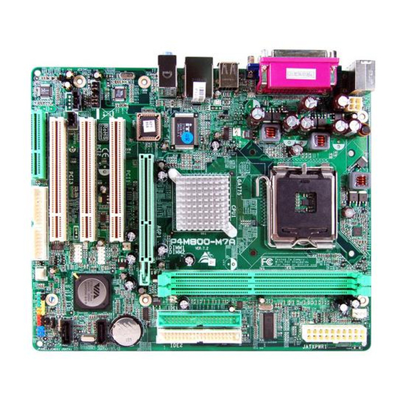
Page 3: Specification
Dual core processor up to 2.8GHz Support 533/800 MHz front-side bus Chipset VIA P4M800ce + 8237R Plus AGPset with VIA Unichrome Pro Graphics core Main Memory Two 184-pin DDR SDRAM DIMM sockets Support single-sided or double-sided 2.5v DDR-266/333/400 DIMMs in 64/128/256/... -
Page 4: Special Features
Audio Onboard Realtek ALC-655 selectable 2 or 6-CH audio CODEC - AC’97 v2.3 compliant - Supports CD-In, Aux-In - Supports automatic “jack-sensing” - Rear panel audio jacks configuration: & r BIOS Flash EEPROM with Award Plug & Play BIOS Support ACPI S3 (Suspend To RAM) mode in ACPI compliant O/S Support EZ Boot for fast bootable device selection Support Magic Health for system hardware status report during system boot-up Special Features... -
Page 5: Block Diagram
1.2 Block Diagram... -
Page 6: Cpu Installation
2. Setting up the mainboard Before assembling the mainboard into the PC case we recommend you to do the following: 1. CPU Installation 2. DDR Memory Insertion After the mainboard is fitted into the case, you may 3. Install Add-on VGA or PCI cards (Optional) 4. - Page 7 Step 3 Step 4 Remove the processor from the protective Hold the processor with thumb and index cover. Do not touch the bottom of the fingers as shown. Ensure fingers align to the processor. The processor cover should not socket cutouts ( D ) , processor notches ( E ) be discarded.
- Page 8 3.2 DDR Memory Insertion The mainboard accommodates two PC2100/PC2700/PC3200 184-pin DIMMs (Dual In-line Memory Modules): • Supports up to 2.0GB of 266/333/400MHz DDR SDRAM. • Supports unbuffered non-ECC DIMMs. • DDR SDRAM supports 64, 128, 256, 512MB and 1GB DIMM modules. •...
-
Page 9: Internal Connectors
3.4 Rear IO Port RJ-45 Parallel Port Line-in/Rear out (Light blue) PS/2 Mouse Line-out/Front out (Lime) PS/2 Mic-in/Center&Subwoofer (Pink) Keyboard USB2.0 ports 3.5 Internal Connectors... - Page 10 Connectors Figure Discriptions CPU / Power Fan Power Connectors JCPU_FAN JCPU_FAN: Connect the CPU fan to this Control Ground JPWR_FAN Sense connector. +12V JPWR_FAN: Use this connector if you are installing an additional fan in the unit. Ground Sense +12V Floppy Drive Connector IDE1 Primary/Secondary IDE Connector...
- Page 11 Connectors Figure Discriptions CUSB3/CUSB4: Four USB2.0 header This mainboard includes 4 additional onboard CUSB3 USB ports. CUSB4 To use these additional USB ports, a USB bracket is required. Please contact your retailer for details. CFP: Case Front Panel Connector HD_LED This LED indicates hard drive activity.
-
Page 12: Bios Setup
4. BIOS BIOS Setup When you start up the computer for the first time you need to enter the BIOS CMOS Setup Utility. Power on the computer and press <Del> key during POST (Power On Self Test). The BIOS CMOS SETUP UTILITY opens as shown below: <... -
Page 13: Driver Installation
Click “VIA LAN Driver” to install LAN driver. Step 4 : Click “VGA Driver” to install onboard graphics driver. Step 5 : Click “USB V2.0 Driver” to install USB 2.0 driver. Step 6 : Click “VIA SATA RAID Driver” to install Serial ATA driver. -
Page 14: Flashing The Bios
6. Flashing the BIOS Do NOT flash the system BIOS unless it is really necessary. Updating and flashing the BIOS content risks BIOS data corruption which may cause system unable to power-on. Download the xxxxx.EXE file corresponding to your model from our website to an empty directory on your hard disk or floppy.
Need help?
Do you have a question about the P4M800 and is the answer not in the manual?
Questions and answers