Table of Contents
Advertisement
User'
User' s s s s s
User'
User'
User'
Manual
Manual
Manual
Manual
Manual
VIA
VIA
P4M266A
P4M266A
VIA
VIA P4M266A
VIA
P4M266A
P4M266A mainboard
for Intel Socket 478 processor
for Intel Socket 478 processor
for Intel Socket 478 processor
for Intel Socket 478 processor
for Intel Socket 478 processor
TRADEMARK
All products and company names are trademarks or registered
trademarks of their respective holders.
These specifications are subject to change without notice.
mainboard
mainboard
mainboard
mainboard
Manual Revision 2.1
May 27, 2004
Advertisement
Table of Contents

Related Manuals for VIA Technologies P4M266A


Summary of Contents for VIA Technologies P4M266A
- Page 1 Manual Manual Manual Manual Manual P4M266A P4M266A mainboard mainboard VIA P4M266A P4M266A P4M266A mainboard mainboard mainboard for Intel Socket 478 processor for Intel Socket 478 processor for Intel Socket 478 processor for Intel Socket 478 processor for Intel Socket 478 processor...
- Page 2 DISCLAIMER OF WARRANTIES: THERE ARE NO WARRANTIES WHICH EXTEND BEYOND THE DESCRIPTION ON THE FACE OF THE MANUFACTURER LIMITED WARRANTY. THE MANUFACTURER EXPRESSLY EXCLUDES ALL OTHER WARRANTIES, EXPRESS OR IMPLIED, REGARDING ITS PRODUCTS; INCLUDING ANY IMPLIED WARRANTIES OF MERCHANTABILITY, FITNESS FOR A PARTICULAR PURPOSE OR NONINFRINGEMENT.
-
Page 3: Table Of Contents
Table of Contents Page Section 1 Introduction Package Contents ............1-1 System Block Diagram ..........1-2 Section 2 Features Mainboard Features ........... 2-1 Section 3 Installatio Mainboard Layout ............. 3-2 Easy Installation Procedure Jumper Settings ............3-3 System Memory Configuration ........3-4 Device Connectors............. -
Page 4: Driver Installation
Page Section 5 Driver Installation Easy Driver Installation ..........5-1 Appendix Appendix A Update Your System BIOS ......... A-1... -
Page 5: Introduction
Introduction Section 1 INTRODUCTION Package Contents Contents Optional Items A. Mainboard G. Extra USB2.0 port cable B. User’s manual H. S/PDIF Module C. Floppy drive cable If you need the optional item, please contact your dealer for assistance. D. HDD drive cable E. -
Page 6: System Block Diagram
Introduction System Block Diagram Figure 2: System Block Diagram Page 1-2... -
Page 7: Features
Socket 478 Intel Celeron processor with 400MHz front side bus up to 2.4 GHz Chipset VIA P4M266A AGPset : VIA P4M266A + VT8235 - Built-in VIA ProSavage 8 Graphics core Main Memory 184-pin DDR DIMM sockets for 64-bit, Unbuffered, Single/Double-... - Page 8 Features IDE --> Embedded IDE controller with 2 ordinary IDE ports up to 4 IDE devices, supports ATA-133 with up to 133MB/sec bandwidth Legacy IO Controller ITE 8705 LPC IO controller for floppy, printer, serial, game and CIR/SIR interface Audio channel audio with analog and digital output - AC’97 v2.3 compliant - In 2-CH mode, supports Line-In (Light blue), Line-Out (Lime) and Mic-In...
-
Page 9: Other Features
Features S/PDIF in/out connector IR connector Front Panel Audio connector Game port connector Fan connectors Front Panel Controller Supports Reset & Soft-Off switches Supports HDD & Power LEDs Supports PC speaker Expansion Slots AGP slot supporting 1.5v AGP cards - AGP v2.0 compliant Three PCI slots with Bus Master support - PCI v2.2 compliant... - Page 10 Features Page 2-4...
-
Page 11: Installation
Installation Section 3 INSTALLATION Page 3-1... -
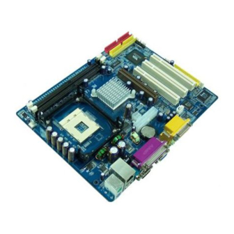
Page 12: Mainboard Layout
Installation Mainboard Layout Page 3-2... -
Page 13: Jumper Settings
Installation 3-1 Jumper Settings JCMOS: Clear CMOS data Jumper If the CMOS data becomes corrupted or you forgot the supervisor or user password, clear the CMOS data to reconfigure the system back to the default values stored in the ROM BIOS. Settings: 1-2: Normal (Default) 2-3: Clear CMOS... -
Page 14: System Memory Configuration
Installation 3-2 System Memory Configuration Memory Layout The mainboard accommodates two PC1600/PC2100 184-pin DIMMs (Dual In-line Memory Modules): • Supports up to 2.0GB of 200/266MHz DDR SDRAM • Supports unbuffered and non-ECC DIMMs • Supports configurations defined in the JEDEC DDR DIMM specification Figure 1 and Table 1 show two possible memory configurations. - Page 15 Installation 3-3 Connectors Parallel Port RJ-45 LAN Line-in/Rear out (Light blue) PS/2 Line-out/Front out (Lime) Mouse PS/2 Mic-in/Center&Subwoofer (Pink) Keyboard COM1 VGA1 USB2.0 USB2.0 ports ports Figure 2 - I/O Ports JCPU_FAN / JSYS_FAN: JCPU_FAN JSYS_FAN CPU/Chassis Fan Power Connectors JCPU_FAN: The CPU must be kept cool by using a heatsink with fan assembly.
- Page 16 Installation Floppy Controller Connector This mainboard is equipped with a floppy disk drive connector for connecting up to 2 floppy disk drives. IDE1 IDE1/IDE2:Ultra DMA-66/100/133 Primary/Secondary IDE Connector IDE2 This mainboard is equipped with 2 IDE disk connec- tors for connecting up to 4 ATA-133 IDE drives. It supports PIO and DMA mode operations for maximum data transfer rate of 133MB/sec per channel.
- Page 17 Installation CFPA: Front Panel Audio Connector When the jumpers are removed this connector can be used for front panel audio. The front panel line-out phone jack should have a “normal close” switch . Without a phone- plug inserted, the rear panel audio is enabled.
- Page 18 Installation S/PDIF: Sony/Philips Digital InterFace connector This connector links digital audio between the mainboard and your audio devices, such as CD player, sampler or DAT recorder. It allows the digital transmission of audio data in S/PDIF format. SPDIF_IN SPDIF_OUT CUSB3: Two USB 2.0 ports This mainboard includes 2 additional onboard USB ports, identified by two 10-pin connector.
- Page 19 Installation CFP: Front Panel Connector HD_LED This LED will light up whenever the hard drive is being accessed. PWR_LED This connects to the power button of the system chassis This switch allows you to reboot without having to power off the system thus prolonging the life of the power supply or system.
-
Page 20: External Modem Ring-In Power On And
Installation External Modem Ring-in Power ON and Keyboard Power ON Functions (KBPO) Modem-Ring Power ON Function The I/O chipset provides the two serial ports with the External Modem Ring-in Power ON function. Once you connect an external modem to COM1 or COM2, the mainboard enables you to turn on the system through remote and host dial-up control. -
Page 21: Bios Setup
BIOS Section 4 BIOS SETUP Main Menu The ROM BIOS provides a built-in Setup program which allows user to modify the basic system configuration and hardware parameters. The modified data is stored in a battery-backed CMOS, so that data will be retained even when the power is turned off. -
Page 22: Standard Cmos Setup
BIOS The main menu displays all the major selection items. Select the item you need to reconfigure. The selection is made by moving the cursor (press any direction (arrow key ) to the item and pressing the ‘Enter’ key. An on-line help message is displayed at the bottom of the screen as the cursor is moved to various items which provides a better understanding of each function. -
Page 23: Advanced Bios Features
BIOS 4-2 Advanced BIOS Features Selecting the “ADVANCED BIOS FEATURES” option in the CMOS SETUP UTILITY menu allows users to change system related parameters in the displayed menu. This menu shows all of the manufacturer’s default values for the board. Pressing the [F1] key displays a help message for the selected item. - Page 24 BIOS CPU L1 & L2 Cache This controls the status of the processor’s internal and external (L2) cache area. Options: Enabled, Disabled. CPU L2 Cache ECC Checking This item allows you to enable/disable CPU L2 Cache ECC checking. Options: Enabled, Disabled. Quick Power On Self Test This category speeds up the Power On Self Test (POST).
- Page 25 BIOS Typematic Rate Setting This determines the keystrokes repeat rate. The default is Disabled. Enabled: Allows typematic rate and typematic delay programming. Disabled: The typematic rate and typematic delay will be controlled by the keyboard controller in your system. Typematic Rate (Chars/Sec) This is the number of characters that will be repeated by a keyboard press.
-
Page 26: Advanced Chipset Features
BIOS 4-3 Advanced Chipset Features Choose the “ADVANCED CHIPSET FEATURES” option in the CMOS SETUP UTILITY menu to display following menu. Figure 4: Chipset Features Setup System BIOS Cacheable This item allows the system to be cached in memory for faster execution. Options: Disabled, Enabled. - Page 27 BIOS DRAM Clock / Drive Control Scroll to DRAM Clock/Drive Control and press <Enter>. The following screen appears: Current FSB Frequency Display the current CPU front side bus frequency information. Current DRAM Frequency Display the current DRAM frequency information. DRAM Clock This item allows you to select DRAM clock.
- Page 28 BIOS Precharge to Active (Trp) This item refers to the number of cycles required to return data to its original location to close the bank or the number of cycles required to page memory before the next bank activate command can be issued. The default is by DRAM SPD. Options: 3T, 2T.
- Page 29 BIOS AGP & P2P Bridge Control Scroll to AGP & P2P Bridge Control and press <Enter>. The following screen appears: AGP Aperture Size (MB) This item defines the size of the aperture if you use an AGP graphics adapter. It refers to a section of the PCI memory address range used for graphics memory.
- Page 30 BIOS CPU & PCI Bus Control Scroll to CPU & PCI Bus Control and press <Enter>. The following screen appears: CPU to PCI Write Buffer When enabled, up to four words of data can be written to the PCI bus without interruting the CPU.
-
Page 31: Integrated Peripherals
BIOS 4-4 Integrated Peripherals Figure 5: Integrated Peripherals Init Display First If two video cards are used (1 AGP and 1 PCI) this specifies which one will be the primary display adapter. The default is PCI Slot. Options: PCI Slot, AGP. VIA OnChip IDE Device Scroll to VIA Onchip IDE Device and press <Enter>. - Page 32 BIOS OnChip IDE Channel0/1 The integrated peripheral controller contains an IDE interface with support for two IDE channels. Select “Enabled” to activate each channel separately. Options: Enabled, Disabled. Note: If you do not use the onboard IDE connector, then you will need to set the Onboard Primary PCI IDE and Onboard Secondary PCI IDE to “Disabled”.
- Page 33 BIOS VIA Onchip PCI Device Scroll to VIA Onchip PCI Device and press <Enter>. The following screen appears: VIA-3058 AC97 Audio This item allows you to disable the chipset on-chip support for AC97 Audio. Options: Auto, Disabled. VIA-3043 Onchip LAN (Optional) Enables the onboard LAN feature.
- Page 34 BIOS Super IO Chip Setup Scroll to Super IO Chip Setup and press <Enter>. The following screen appears: Onboard FDC Controller Select Enabled if your system has a floppy disk controller (FDC) installed on the system board and you wish to use it. If you install add-in FDC or the system has no floppy drive, select Disabled in this field.
- Page 35 BIOS Game Port Address Select an address for the Game port. Options: 201, 209, Disabled. Midi Port Address Select an address for the Midi port. Options: 300, 330, Disabled. Midi Port IRQ Select an interrupt for the Midi port. Options: 5, 10. Page 4-15...
-
Page 36: Power Management Setup
BIOS 4-5 Power Management Setup Choose the “POWER MANAGEMENT SETUP” in the CMOS SETUP UTILITY to display the following screen. This menu allows the user to modify the power management parameters and IRQ signals. In general, these parameters should not be changed unless it’s absolutely necessary. - Page 37 BIOS HDD Power Down Powers down the hard disk drive after a preset period of system inactivity. Options: Disabled, 1 ~ 15 Min. Suspend Mode Automatically, shuts off all devices except the CPU after a preset period of system inactivity. Options: Disabled, 1 , 2, 4 ,6, 8, 10, 20, 30, 40 min and 1 hour .
- Page 38 BIOS Run VGABIOS if S3 Resume (Optional) This determines whether or not to enable the system to run the VGA BIOS when resuming from S3(STR) or S1&S3. Options: Auto, Yes, No. PWRON After PWR-Fail This item enables your computer to automatically restart or return to its last operat- ing status after power returns from a power failure.
-
Page 39: Pnp/Pci Configuration Setup
BIOS USB Resume from S3 (Optional) This item allows you to wake-up the system by USB device when you save the computer power at S3. Options: Enabled, Disabled. PowerOn by PCI Card An input signal form PME on the PCI card awakens the system from a soft off state. Options: Enabled, Disabled. - Page 40 BIOS Resources Controlled By Determines what controls system PNP/PCI resources. The default is Auto (ESCD). Manual: PNP Card’s resources are controlled manually. The “IRQ Resources” field becomes available and you can set which IRQ-X and DMA-X are assigned to PCI and onboard devices. Auto: BIOS assigns the interrupt resource automatically.
-
Page 41: Pc Health Status
BIOS 4-7 PC Health Status Figure 8: PC Health Status Show PC Health in POST When this function is enabled the PC Health information is displayed during the POST (Power On Self Test). Options: Disabled, Enabled. Current System/CPU Temperature Displays the current system/CPU temperature. Current CPU/Chassis FAN Speed Displays the current speed of the CPU and chassis fan speed in RPMs. -
Page 42: Power Bios Features
BIOS 4-8 Power BIOS Features This page lets you adjust various parameters to obtain improved performance for overclocking. Warning: Overclocking requires expert knowledge and risks permanent damage to system components. We recommend you leave these parameters at their default values for proper operation. Figure 9: Frequency/Voltage Control CPU Clock Ratio Use this item to select a multiplier for the system front side bus (FSB) frequency. - Page 43 BIOS Key in the DEC (decimal) number for the CPU Clock Ratio. Auto Detect PCI/DIMM Clk When enabled the mainboard automatically disables the clock source for a PCI/ DIMM slot which does not have a module in it, reducing EMI (ElectroMagnetic Interference).
-
Page 44: Defaults Menu
BIOS 4-9 Defaults Menu Selecting “Defaults” from the main menu shows you two options which are de- scribed below Load Fail-Safe Defaults When you press <Enter> on this item you get a confirmation dialog box: Load Fail-Safe Defaults (Y/N) ? N Pressing ‘Y’... -
Page 45: Supervisor/User Password Setting
BIOS 4-10 Supervisor/User Password Setting You can set either supervisor or user password, or both. The differences between are: supervisor password: full rights to enter and change the options of the setup menus. user password: only enter but do not have the right to change the options of the setup menus. -
Page 46: Exit Without Saving
BIOS 4-11 Exiting BIOS Save & Exit Setup Pressing <Enter> on this item asks for confirmation: Save to CMOS and EXIT (Y/N)? Y Pressing “Y” stores the selections made in the menus in CMOS – a special section of memory that stays on after you turn your system off. The next time you boot your computer, the BIOS configures your system according to the Setup selections stored in CMOS. -
Page 47: Easy Driver Installation
Section 5 DRIVER INSTALLATION Easy Driver Installation [ VIA P4M266A Series ] Insert the bundled CD-disk, the main menu screen will appear. The main menu displays buttons that link you to the supported drivers, utilities and software. Step 1 : Click “VIA SERIES PACK 4IN1 DRIVER”... - Page 48 Drivers Installation Page 5-2...
-
Page 49: Update Your System Bios
Appendix Appendix A A-1 Update Your System BIOS Download the xxxxx.EXE file corresponding to your model from our website to an empty directory on your hard disk or floppy. Run the downloaded xxxxx.EXE file and it will self extract. Copy these extracted files to a bootable floppy disk. Note: The floppy disk should contain NO device drivers or other programs. - Page 50 Appendix 5. Key in File Name to save previous BIOS to file. XXXX XXXXX xxxxx.bin xxxxx.bin 6. To confirm and proceed, please key in [Y] to start the programming. XXXX XXXXX xxxxx.bin xxxxx.bin 7. The BIOS update is finished. XXXX XXXXX xxxxx.bin F10 : Exit...
Need help?
Do you have a question about the P4M266A and is the answer not in the manual?
Questions and answers