Table of Contents
Advertisement
Federal Communications Commission (FCC) Statement
Federal Communications Commission (FCC) Statement
Federal Communications Commission (FCC) Statement
Federal Communications Commission (FCC) Statement
Federal Communications Commission (FCC) Statement
This equipment has been tested and found to comply with the limits for a Class B digital
device, pursuant to Part 15 of FCC Rules. These limits are designed to provide reasonable
protection against harmful interference in a residential installation. This equipment
generates, uses and can radiate radio frequency energy and, if not installed and used in
accordance with instructions contained in this manual, may cause harmful interference
to radio and television communications. However, there is no guarantee that interference
will not occur in a particular installation.
If this equipment does cause harmful interference to radio or television reception, which
can be determined by turning the equipment off and on, the user is encouraged to try to
correct the interference by one or more of the following measures:
-
REORIENT OR RELOCATE THE RECEIVING ANTENNA
-
INCREASE THE SEPARATION BETWEEN THE EQUIPMENT AND THE RECEIVER
-
CONNECT THE EQUIPMENT INTO AN OUTLET ON A CIRCUIT DIFFERENT FROM
THAT OF THE RECEIVER
-
CONSULT THE DEALER OR AN EXPERIENCED AUDIO/TELEVISION TECHNICIAN
NOTE: Connecting this device to peripheral devices that do not comply with Class B
requirements, or using an unshielded peripheral data cable, could also result in
harmful interference to radio or television reception.
The user is cautioned that any changes or modifications not expressly approved
by the party responsible for compliance could void the user's authority to operate
this equipment.
To ensure that the use of this product does not contribute to interference, it is
necessary to use shielded I/O cables.
Copyright
Copyright
Copyright
Copyright
Copyright
This manual is copyrighted with all rights reserved. No portion of this manual may be
copied or reproduced by any means.
While every precaution has been taken in the preparation of this manual, no responsibility
for errors or omissions is assumed. Neither is any liability assumed for damages resulting
from the use of the information contained herein.
Trademarks
Trademarks
Trademarks
Trademarks
Trademarks
All brand names, logos and registered trademarks mentioned are property of their
respective owners.
Electronic Emission Notices
Electronic Emission Notices
Electronic Emission Notices
Electronic Emission Notices
Electronic Emission Notices
1 1 1 1 1
Advertisement
Table of Contents

Subscribe to Our Youtube Channel
Related Manuals for VIA Technologies P4M800 Pro


Summary of Contents for VIA Technologies P4M800 Pro
- Page 1 1 1 1 1 1 Electronic Emission Notices Electronic Emission Notices Electronic Emission Notices Electronic Emission Notices Electronic Emission Notices Federal Communications Commission (FCC) Statement Federal Communications Commission (FCC) Statement Federal Communications Commission (FCC) Statement Federal Communications Commission (FCC) Statement Federal Communications Commission (FCC) Statement This equipment has been tested and found to comply with the limits for a Class B digital device, pursuant to Part 15 of FCC Rules.
-
Page 2: Table Of Contents
2 2 2 2 2 T T T T T able of Contents able of Contents able of Contents able of Contents able of Contents HARDWARE CONFIGURATION HARDWARE CONFIGURATION HARDWARE CONFIGURATION ............................................HARDWARE CONFIGURATION HARDWARE CONFIGURATION ............4 4 4 4 4 Key Features .................... - Page 3 3 3 3 3 3 INSTALL DDRII DIMMS INSTALL DDRII DIMMS INSTALL DDRII DIMMS ......................................................29 INSTALL DDRII DIMMS INSTALL DDRII DIMMS ..............BIOS SETUP BIOS SETUP ..................................BIOS SETUP BIOS SETUP BIOS SETUP ....................................................
-
Page 4: Key Features
Features : : : : : Features Key Features Features Chipset Chipset Chipset Chipset Chipset • VIA P4M800 Pro+VT8237R PLUS chipset. Processor Processor Processor Processor Processor • Supports Intel® Celeron® , Pentium® 4 processors in the LGA775 package (with 0.8V~1.6V voltage). •... - Page 5 5 5 5 5 5 Serial A Serial A Serial A Serial A Serial AT T T T T A/RAID Controller (optional) A/RAID Controller (optional) A/RAID Controller (optional) A/RAID Controller (optional) A/RAID Controller (optional) • Complies with Serial ATA Specificaion Revision 1.0. •...
- Page 6 6 6 6 6 6 Integrated Unichrome Integrated Unichrome Integrated Unichrome Integrated Unichrome Integrated Unichrome Pro GFX /Video Accelerator Pro GFX /Video Accelerator Pro GFX /Video Accelerator Pro GFX /Video Accelerator Pro GFX /Video Accelerator • Optimized Shared Memory Architecture (SMA). •...
-
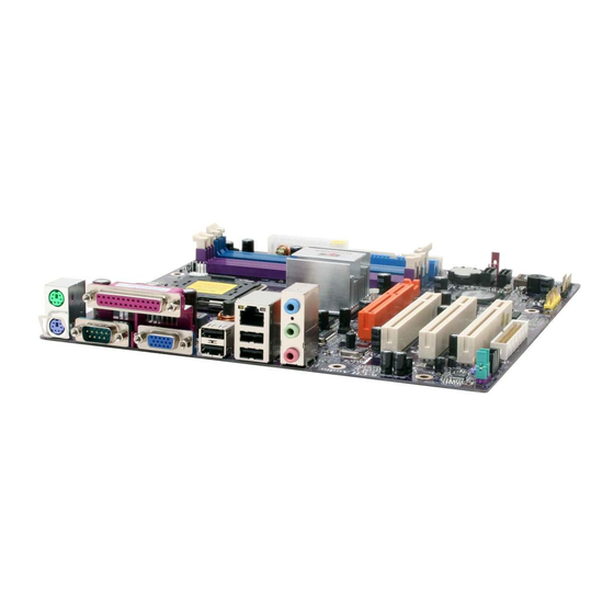
Page 7: Motherboard Layout
7 7 7 7 7 Motherboard Layout Motherboard Layout Motherboard Layout Motherboard Layout Motherboard Layout The following diagram shows the relative positions of the jumpers, connectors, major components and memory banks on the motherboard. LGA775 Socket NOTE 1) Be sure to check the cable orientation in order to match the colored strip to the pin 1 end of the connector. -
Page 8: Rear Prear Panel Anel Anel
8 8 8 8 8 Rear Panel Rear Panel Rear Panel Rear Panel Rear Panel The back panel provides the following connectors: Mouse Connector Mouse Connector Mouse Connector Mouse Connector Mouse Connector The mainboard provides a standard PS/2 mouse mini DIN connector for ®... - Page 9 9 9 9 9 9 Serial Port Connector: COM Serial Port Connector: COM Serial Port Connector: COM Serial Port Connector: COM Serial Port Connector: COM The Port is 16550A high speed communication ports that send/receive 16bytes FIFOs. You can attach a serial mouse or other serial devices directly to the connectors.
-
Page 10: Audio Configuration
Audio Configuration Audio Configuration Audio Configuration Audio Configuration Audio Configuration After installing the audio driver, you can select 4/6 channel surround audio output in the software utility and then connect surround speakers to appropriate audio ports. There are two ways to obtain 4/6 channel surround audio output: 1. - Page 11 In the software utility, double click “AC97 Audio configuration” icon from the window taskbar on the right bottom. Then the “AC97 Audio Configuration” box will appear. Click on the Speaker Configuration tab to select the audio mode. A. When you choose 4-channel mode for 4 speaker output, the selected item is shown below.
-
Page 12: Method 2: Using S-Bracket Connectors
Method 2: Using S-BRACKET connectors: The S-Bracket (shown on page 22) is an optional accessory. It gives access to analog and digital audio output by integrating both SPDIF and analog LINE OUT connectors. To use the S-Bracket, you should select the correct setting in the software utility. -
Page 13: Jumper Setting
Jumper Settings Jumper Settings Jumper Settings Jumper Settings Jumper Settings This chapter explains how to configure the motherboard’s hardware. Before using your computer, make sure all jumpers and DRAM modules are set correctly. Refer to this chapter whenever in doubt. JBAT1 - CMOS Clear JBAT1 - CMOS Clear JBAT1 - CMOS Clear... -
Page 14: Connectors
Connectors Connectors Connectors Connectors Connectors The motherboard provides connectors to connect to FDD, IDE HDD, and USB Ports and to the CPU/System FAN etc. Floppy Disk Drive Connector - CN3 The motherboard provides a standard floppy disk drive connector that supports 1.44M, 2.88M floppy disk types. -
Page 15: Serial Ata Hard Disk Connectors - Sata-1, Sata-2
Serial ATA Hard Disk Connectors - SATA-1, SATA-2 (optional) The mainboard has 2 SATA connectors. The mainboard provides dual high- speed Serial ATA interface ports SATA-1,SATA-2. Each supports 1 generation serial ATA data rates of 150 MB/s. Both connectors are fully compliant with Serial ATA 1.0 specifications. - Page 16 Serial A Serial A Serial A Serial A Serial AT T T T T A Cable (optional) A Cable (optional) A Cable (optional) A Cable (optional) A Cable (optional) Connect one end of the SATA cable to the mainboard, and connect the other end to the SATA Hard Disk.
-
Page 17: Usb Connectors - Usb1, Usb2, Usb3
USB Connectors - USB1, USB2, USB3 USB Connectors - USB1, USB2, USB3 USB Connectors - USB1, USB2, USB3 USB Connectors - USB1, USB2, USB3 USB Connectors - USB1, USB2, USB3 This mainboard has USB ports. Some computer cases have a special module that mounts USB ports at the front of the case. -
Page 18: Fan Power Connectors - Cpu Fan, Sys Fan
Fan Power Header - CPUFAN, SYSFAN Fan Power Header - CPUFAN, SYSFAN Fan Power Header - CPUFAN, SYSFAN Fan Power Header - CPUFAN, SYSFAN Fan Power Header - CPUFAN, SYSFAN The CPUFAN1 (processor fan) and SYSFAN1 (system fan) support system cooling fans using +12V via a four/three-pin head connector. -
Page 19: Cd-In Connector - Cds1
CD-IN Connector - CDS1 CD-IN Connector - CDS1 CD-IN Connector - CDS1 CD-IN Connector - CDS1 CD-IN Connector - CDS1 The connector is for CD-ROM Drive. CDS1 CDS1 CDS1 CDS1 CDS1 CDS1 Assignment CD-L CD-R... -
Page 20: Front Panel Audio Header - Fps1
Front Panel Audio Header - FPS1 Front Panel Audio Header - FPS1 Front Panel Audio Header - FPS1 Front Panel Audio Header - FPS1 Front Panel Audio Header - FPS1 This mainboard supports front panel microphone and speaker out ports. If your computer case has these ports, connect them to FPS1. -
Page 21: Cn6 (Optional)
S-Bracket(SPDIF)/CEN/LFE/Surround Output /CEN/LFE/Surround Output /CEN/LFE/Surround Output Connector /CEN/LFE/Surround Output /CEN/LFE/Surround Output - CN6 (optional) The connector allows you to connect a S-Bracket for a Digital Interface (SPDIF). The S-Bracket offers 1 SPDIF jacks for digital audio transmission and 2 analog Line-Out jacks for other 4-channel audio output. - Page 22 CN6- CN6- CN6-S S S S S -Brack -Brack -Brack -Bracket et et et et CN6- CN6- -Brack SIGNAL DESCRIPTION SOUT-L Audio left surrounding output SOUT-R Audio right surrounding output Ground Ground CET-OUT Audio center output LFE-OUT Audio bass output Ground SPDIF S/PDIF input...
-
Page 23: Front Panel Header - Fp1
Front Panel Header - FP1 Front Panel Header - FP1 Front Panel Header - FP1 Front Panel Header - FP1 Front Panel Header - FP1 The mainboard provides one front panel connector for electrical connect on to the front panel switches and LEDs. SPEAKER IRRX IRTX... -
Page 24: Slots
Slots Slots Slots Slots Slots The motherboard provides one AGP slot, two 32-bit PCI bus slots. AGP Slot AGP Slot AGP Slot AGP Slot AGP Slot PCI Slots PCI Slots PCI Slots PCI Slots PCI Slots AGP (Accelerated Graphics Port) Slot AGP (Accelerated Graphics Port) Slot AGP (Accelerated Graphics Port) Slot AGP (Accelerated Graphics Port) Slot... -
Page 25: Cpu Installation
CPU Installation CPU Installation CPU Installation CPU Installation CPU Installation Please refer to the following steps to install the CPU. 1.Use index finger and thumb to move metal lever so it is separated from the bottom steel shell grip hook. 2.Use index finger to lift the top steel shell. - Page 26 4.Use index finger and thumb to press down metal lever, the cap will be pushed up by the CPU; this may also be done by removing the cap beforehand. 5.Press the metal lever so it is secured in the bottom steel shell grip hook.
- Page 27 6. It’s recommended that the CPU heatsink should be an approval by Intel corporation design for Prescott CPU. Choose the orientation of the thermal solution for optimal wire routing to the fan header on the motherboard, Position the thermal solution over the processor. Ensure the fan wiring is positioned to prevent wire pinching between the heatsink and the processor, or between the heatsink clip and the socket.
- Page 28 9. Gently rotate the cap clockwise 1/4 turn. 10. At last, attach the fan wire connector to the 4 pin fan header connector on the motherboard labeled CPU FAN. Technical Reference Booklet...
-
Page 29: Install Ddrii Dimms
Install DDRII DIMMs Please follow the steps below to install DDRII DIMMs. 1. Locate the DDRII DIMM sockets. 2. Holding the DDRII DIMM by the edges, remove it from its antistatic package. 3. Make sure the clips at either end of the socket are pushed away from the socket. -
Page 30: Bios Setup
BIOS SETUP About the Setup Utility The computer uses the latest Award BIOS with support for Windows Plug and Play. The CMOS chip on the motherboard contains the ROM setup instructions for configuring the motherboard BIOS. The BIOS (Basic Input and Output System) Setup Utility displays the system’s configuration status and provides you with options to set system parameters. -
Page 31: Main Menu
Main Menu Once you enter the Award BIOS CMOS Setup Utility, the Main Menu will appear on the screen. The Main Menu allows you to select from various setup functions and two exit choices. Use the arrow keys to select among the items and press <Enter> to accept and enter the sub-menu. -
Page 32: Standard Cmos Features
Load Optimized The chipset defaults are settings which provide for maximum Defaults system performance. While Award has designed the custom BIOS to maximize performance, the manufacturer has the right to change these defaults to meet its needs. Set Supervisor/ Changes, sets, or disables password. It allows you to limit User Password access to the system and the Setup Program. -
Page 33: Advanced Bios Features
IDE Channel These categories identify the types of the two channels that have been installed in the computer. If the controller of the HDD interface is SCSI, the selection shall be “None”. Drive A / This category identifies the driver types which have been installed Drive B in the computer. -
Page 34: Frequency/Voltage Control
Frequency/V Frequency/V oltage Control oltage Control Frequency/V Frequency/V Frequency/Voltage Control oltage Control oltage Control This section allows you to set CPU Speed. Set Supervisor/User Password Set Supervisor/User Password Set Supervisor/User Password Set Supervisor/User Password Set Supervisor/User Password You can set either a supervisor or a user password or both. The difference between them is: Supervisor Password : You can enter the Setup Program and change... -
Page 35: Flash Update Procedure
Flash Update Procedure Flash Update Procedure Flash Update Procedure Flash Update Procedure Flash Update Procedure A program AWDFLASH.EXE is included in the utility diskette or CD (X:\Utility\ AWDFLASH.EXE). Please follow the recommended procedure to update the flash BIOS, as listed below: (X: your CD driver letter). -
Page 36: Vt8237R Plus Sata Raid User Manual Vt8237R Plus Sata Raid User Manual
When the system powers on, the following information will appear on screen. Press the ‘Tab’ key to enter BIOS configuration utility. VIA Technologies,Inc.VIA Serial ATA RAID BIOS Setting Utility v4.90 Copyright (C) VIA Technologies,Inc.All Right reserved. Scan Devices,Please wait . . . -
Page 37: Create Disk Array
Create Disk Array 1. Use the arrow keys to navigate the main menu. Use the up and down arrow keys to select the Create Array command and press <Enter> to call out the list of creation steps. VIA Tech. VT8237 Series SATA RAID BIOS Ver 4.90 Auto Setup For Data Security Create a RAID array with Array Mode RAID 1 (Mirroring) - Page 38 3. After selected array mode, there are two methods to create a disk array. One method is “Auto Setup” another is “Select Disk Drives”. Auto Setup let BIOS select the disk drives and create array automatically. Select Disk Drives let user select the array drives by required.
-
Page 39: Delete Disk Array
5. Use the arrow key to highlight Start Create Process and press <Enter>. A warning message will appear, press Y to finish the creation, or press N to cancel the creation. 6. Please note that all existing content in the hard drive will be destroyed after the array creation. -
Page 40: Duplicate Critical Raid 1 Array
VIA Tech. VT8237 Series SATA RAID BIOS Ver 4.90 Create Array Sct/Clear bootable array Delete Array Create/Delete Spare Select Boot Array Serial Number View : View Array/disk Status : Move to next item Enter : Confirm the selection ESC : Exit Channel Drive Name Array Name... -
Page 41: Rebuild Broken Raid 1 Array
Rebuild Broken RAID 1 Array When booting up the system, BIOS will detect if any member disk drives of RAID has failed or is absent. If BIOS detects any disk drive failures or missing disk drives, the status of the array will be marked as broken. If BIOS detects a broken RAID 1 array but there is a spare hard drive available for rebuilding the broken array, the spare hard drive will automatically become the mirroring drive. - Page 42 1. Power off and Check the Failed Drive: This item enables users to turn off the computer and replace the failed hard drive with a good one. If users’ computer does not support APM, the computer would need to be turned off manually.
-
Page 43: Driver And Raid Software Installation Driver And Raid Software Installation
DRIVER AND RAID SOFTW DRIVER AND RAID SOFTW DRIVER AND RAID SOFTWARE INST ARE INST ARE INSTALLA ARE INST ALLA ALLATION ALLA TION TION TION DRIVER AND RAID SOFTW DRIVER AND RAID SOFTW ARE INST ALLA TION Microsoft Windows Driver Installation 1. - Page 44 3. Confirm the follow-up dialogue windows to finish the installation. 4. When installation is completed, click Finish to restart the system. Technical Reference Booklet...
-
Page 45: Of Vt8237R Plus
Install Operating System into SA Install Operating System into SAT T T T T A HDD Install Operating System into SA A HDD A HDD A HDD Install Operating System into SA Install Operating System into SA A HDD of VT8237R PLUS of VT8237R PLUS of VT8237R PLUS of VT8237R PLUS... - Page 46 Technical Reference Booklet...
- Page 48 0038A8 Technical Reference Booklet...
Need help?
Do you have a question about the P4M800 Pro and is the answer not in the manual?
Questions and answers