Table of Contents
Advertisement
Quick Links
Download this manual
See also:
User Manual
Advertisement
Table of Contents

Subscribe to Our Youtube Channel
Related Manuals for Gefen EXT-WRS232


Summary of Contents for Gefen EXT-WRS232
- Page 1 ® Wireless RS232 Extender EXT-WRS232 User Manual www.gefen.com...
- Page 3 ASKING FOR ASSISTANCE Technical Support: Telephone (818) 772-9100 (800) 545-6900 Fax (818) 772-9120 Technical Support Hours: 8:00 AM to 5:00 PM PST Monday thru Friday PST Write To: Gefen, LLC. c/o Customer Service 20600 Nordhoff St Chatsworth, CA 91311 www.gefen.com support@gefen.com Notice Gefen LLC reserves the right to make changes in the hardware, packaging and any accompanying documentation without prior written notice. Wireless RS-232 Extender is a trademark of Gefen LLC © 2010 Gefen LLC, All Rights Reserved All trademarks are the property of their respective owners. Rev A5...
-
Page 4: Table Of Contents
CONTENTS CONTENTS CONTENTS CONTENTS Introduction FCC Statement And Industry Canada Statements Features Operation Notes Sender Unit Panel Layout Sender Unit Panel Description Receiver Unit Panel Layout Receiver Unit Panel Descriptions 10 Sender Unit / Receiver Unit Layout (Bottom) 11 Sender Unit / Receiver Unit Descriptions (Bottom) 12-16 Connecting And Operating The Wireless RS-232 Extender 16 Erasing The Electronic Serial Numbers (ESNS) -
Page 5: Introduction
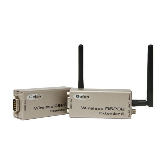
INTRODUCTION Congratulations on your purchase of the Wireless RS-232 Extender. Your complete satisfaction is very important to us. Gefen Gefen delivers innovative, progressive computer and electronics add-on solutions that harness integration, extension, distribution and conversion technologies. Gefen’s reliable, plug-and-play products supplement cross-platform computer systems, professional audio/video environments and HDTV systems of all sizes with hard-working solutions that are easy to implement and simple to operate. The Gefen Wireless RS-232 Extender Extend the connection and control of RS-232 devices up to 100 feet away from your computer, without the hassle of using RS-232 cables. Control your favorite Gefen products or any devices that use the RS-232 serial control interface. How It Works Simply connect the Gefen Wireless RS-232 Extender Sender unit to a computer (or other RS-232 control device) using the supplied RS-232 serial cable. Connect the Receiver unit to the device being controlled using another RS-232 cable. Select the correct baud rate (either 9600 or 19200) on both the Sender unit and Receiver unit, using the DIP switch bank on the bottom of both units. Connect the included 5V DC power supplies to both the Sender unit and Receiver unit. The Gefen Wireless RS-232 Extender will connect a computer wirelessly to the device attached to the Receiver unit, as if the RS-232 host device were attached directly to the client. -
Page 6: Fcc Statement And Industry Canada Statements
FCC STATEmENT AND INDUSTRy CANADA STATEmENTS This device complies with part 15 of the FCC Rules. Operation is subject to the following two conditions: (1) This device may not cause harmful interference, and (2) this device must accept any interference received, including interference that may cause undesired operation INSTRUCTION TO THE USER... - Page 7 FCC STATEmENT AND INDUSTRy CANADA STATEmENTS INDUSTRy CANADA (IC) STATEmENT: Applicant’s Name: Gefen, LLC Manufacturer’s Trade Name: Gefen model / IC ID Numbers: EXT-WRS232R (IC:9057A-EXTWRS232R) EXT-WRS232S (IC:9057A-EXTWRS232S) The wireless radio of this device complies with IC RSS-210 Industry Canada. Operation is subject to the following two conditions: (1) this device may not cause interference,and (2) this device must accept any interference, including interference that may cause undesired operation of the device. To reduce potential radio interference to other users, the antenna type and its gain should be so chosen that the equivalent isotropically radiated power (EIRP) is not more than that required for successful communication. This device has been designed to operate with the antennas provided, and having a maximum gain of 2.5 dBi. Antennas not included with this product or having a gain greater than 2.5 dBi are strictly prohibited for use with this device. The required antenna impedance is 50 Ohms.
-
Page 8: Features
FEATURES Features • Extends any RS-232 compliant device up to 100 feet (30 meters) from a computer or other RS-232 controller • Metal enclose immune to EMI interference • No cables are required for extension • Secure locking power connector prevents accidental power disruption due to stress on power connector • Two selectable baud rates: 9600 or 19200 (please see page 12 for details) • Unlimited number of nodes when using multiple Sender units and Receiver units in a wireless RS-232 network (one-to-many, many-to-one, or many-to- many) • Perfect for digital signage applications • Quick and easy set up Package Includes: (1) Wireless RS-232 Sender unit Unit (1) Wireless RS-232 Receiver unit Unit (1) 6-foot RS-232 serial cable (2) 5V DC External locking power supply (1) User’s Manual... -
Page 9: Operation Notes
OPERATION NOTES READ THESE NOTES BEFORE INSTALLING OR OPERATING THE WIRELESS FOR RS-232 The Wireless RS232 Extender is capable of operating at a baud rate of either 9600 or 19200. Please see page #12 for details on setting the correct baud rate for your RS232 device. The metal housing is immune to EMI interference and the external antenna is capable of extending RS-232 control up to 100 feet (30 meters) through 8 brick walls. Multiple Sender units can also operate simultaneously, allowing greater flexibility in a wireless RS-232 solution. Please see page #13 for details on setting up a wireless RS232 network. Although the Sender unit can be used without external power, the RS-232 protocol does not outline specific guidelines for sending power to another RS-232 device. In most cases, only a small amount of power can be extracted (~10mA) from the DTR (Data Terminal Ready) and RTS (Ready To Send) lines. This is only suitable for lower power devices (e.g. mouse devices). If there is not enough available power, the LED stays in the OFF state. -
Page 10: Sender Unit Panel Layout
SENDER UNIT PANEL LAyOUT Front Panel Back Panel... -
Page 11: Sender Unit Panel Description
SENDER UNIT PANEL DESCRIPTION RS-232 Input Port This port accepts the female end of an RS-232 serial cable. Power LED The LED will glow red when power is applied to the unit. Antenna Transmits RS-232 data to the Receiver unit. 5V DC Power Receptacle This port accepts power from one of the included 5V DC power supplies. -
Page 12: Receiver Unit Panel Layout
RECEIVER UNIT PANEL LAyOUT Front Panel Back Panel... -
Page 13: Receiver Unit Panel Descriptions
RECEIVER UNIT PANEL DESCRIPTIONS RS-232 Output Connector This port accepts the male end of an RS-232 serial cable. Power LED The LED will glow red when power is applied to the unit. Antenna Receives RS-232 data from the Sender unit. 5V DC Power Receptacle This port accepts power from one of the included 5V DC power supplies. -
Page 14: Sender Unit / Receiver Unit Layout (Bottom)
SENDER / RECEIVER UNIT LAyOUT (BOTTOm) Underneath Receiver unit Underneath Sender unit... -
Page 15: Sender Unit / Receiver Unit Descriptions (Bottom)
SENDER / RECEIVER UNIT DESCRIPTIONS (BOTTOm) Receiver Unit L -Tact Switch Used to pair a Receiver unit with a Sender unit. Receiver Unit DIP Switch Bank Used to switch between network modes and select the baud rate. Receiver Unit S -Tact Switch Used to pair a Receiver unit with a Sender unit. Sender Unit Unit L -Tact Switch Used to pair a Receiver unit with a Sender unit. Sender Unit Unit DIP Switch Bank Used to switch between network modes and select the baud rate. Sender Unit Unit S -Tact Switch Used to pair a Receiver unit with a Sender unit. -
Page 16: Connecting And Operating The Wireless Rs-232 Extender
CONNECTING AND OPERATING THE WIRELESS RS-232 EXTENDER How to Connect the Wireless RS-232 Extender 1. Connect a RS-232 cable from the controlling device to the RS-232 input on the Sender unit using the supplied RS-232 serial cable. 2. Connect another RS-232 cable from the RS-232 output connector on the Receiver unit to the RS-232 port on the device you wish to control. 3. Connect the included 5V DC power supplies to the power receptacles on both the Sender unit and Receiver unit. 4. Refer to the section below on how to set the baud rate and using the tact switches for configuring RS-232 device assignment. How to Operate the Wireless RS-232 Extender Setting the Baud Rate RS-232 devices will function at different baud rates. It is important that the correct baud rate be set on both the Wireless RS-232 Sender unit and Wireless RS-232 Receiver unit to establish successful communication between the RS- 232 controller (host) and the RS-232 device you wish to manage (client). - Page 17 CONNECTING AND OPERATING THE WIRELESS RS-232 EXTENDER Wireless RS-232 Extender Networks In addition to a simple Sender unit-Receiver unit topology pair, the Wireless RS-232 Extender can be configured to communicate between multiple RS-232 Sender units and RS-232 Receiver units. This allows the creation of a wireless RS-232 network. You may configure your Wireless RS-232 Extender network to operate in the following modes: 1. One Sender unit communicating with multiple Receiver units. 2. Several Sender units communicating with one Receiver unit. 3. Several Sender units communicating with several Receiver units. Controlling a Single RS-232 Device from Different Locations Receiver Unit Wireless extension up to 100 feet. Sender Units 1. Using the DIP switch chart as a guide, set DIP switch #2 to the baud rate used by the devices you wish to control. All Wireless RS-232 Receiver units must be set to the same baud rate rate.
- Page 18 CONNECTING AND OPERATING THE WIRELESS RS-232 EXTENDER 5. Depress the S-Tact switch on the Sender unit. During this process, an Electronic Serial Number (ESN) will be sent from the Sender unit to the Receiver unit. The LED on the front of the unit will blink 3 times between red and green. This indicates the successful completion of the learning process. 6. Repeat steps 4 and 5 for each Sender unit. It is not necessary to have the Sender unit and Receiver units connected to the host and client during the learning process. 7. Once all Receiver units have been configured, you should now be able to control your client RS-232 device from multiple locations. Controlling Several RS-232 Devices from a Single Location Sender Unit Receiver Units Wireless extension up to 100 feet. 1. Using the DIP switch chart set DIP switch #2 to the correct baud rate used by your RS-232 devices. Since only one Receiver unit will be controlling multiple Receiver units, you must ensure that both Sender unit and each Receiver unit are set to the same baud rate.
- Page 19 CONNECTING AND OPERATING THE WIRELESS RS-232 EXTENDER 5. Depress the S-Tact switch on the Sender unit. During this process, an Electronic Serial Number (ESN) will be sent from the Sender unit to the Receiver unit. The LED on the front of the unit will blink 3 times between red and green. This indicates the successful completion of the learning process. 6. Repeat steps 4 and 5 for each Receiver unit. It is not necessary to have each Receiver unit connected to the client (device being controlled) during the learning process. 7. Once all Receiver units have been configured, you should be able to control several RS-232 devices from a single location. Controlling Separate RS-232 Devices with Different Sender units and Receiver units Sender Units Wireless extension up to 100 feet. Receiver Units 1. Using the DIP switch chart as a guide, set DIP switch #2 to the correct baud rate used by each RS-232 device. Since you will be controlling separate RS-232 devices, ensure each RS-232 Sender unit and Receiver unit is set to...
-
Page 20: Erasing The Electronic Serial Numbers (Esns)
CONNECTING AND OPERATING THE WIRELESS RS-232 E 5. Depress the S-Tact switch on the first Sender unit. During this process, an Electronic Serial Number (ESN) will be sent from the Sender unit to the Receiver unit. The LED on the front of the unit will blink 3 times between red and green. This indicates the successful completion of the learning process. 6. Repeat steps 4 and 5 for each Sender unit / Receiver unit Pair. It is not necessary to have each Sender unit / Receiver unit connected to the host / client during the learning process. 7. Once each Sender unit / Receiver unit pair has been configured, you can control several RS-232 devices from a single location. Erasing the Electronic Serial Numbers (ESNs) If you want to remove a Receiver unit and place it within another RS-232 wire- less network, ESNs cannot be deleted individually. You must clear the entire list of “learned” ESNs. To clear the ESN list, hold down the L-Tact button on the Receiver unit for 10 seconds. The LED on the front of the unit will alternate between red and green then return to red which will indicate completion of the erasing process. -
Page 21: Specifications
SPECIFICATIONS RF Band..................... 2.4 GHz RS-232 Sender unit..................DB-9 (F) RS-232 Receiver unit.................DB-9 (F) Power Supply........5V DC, Locking (Sender unit / Receiver unit) Power Consumption................100mW (max) Dimensions.................1.2” W x 3.8” D x 1.2” H Shipping Weight....................2 lbs... -
Page 22: Warranty
This warranty is in lieu of all other warranties expressed or implied, including without limitation, any implied warranty or merchantability or fitness for any particular purpose, all of which are expressly disclaimed. 1. Proof of sale may be required in order to claim warranty. 2. Customers outside the US are responsible for shipping charges to and from Gefen. 3. Copper cables are limited to a 30 day warranty and cables must be in their original condition. The information in this manual has been carefully checked and is believed to be accurate. However, Gefen assumes no responsibility for any inaccuracies that may be contained in this manual. In no event will Gefen be liable for direct, indirect, special, incidental, or consequential damages resulting from any defect or omission in this manual, even if advised of the possibility of such damages. The technical information contained herein regarding the features and specifications is subject to change without notice. For the latest warranty coverage information, please visit Gefen’s Warranty web page at http://www.gefen.com/kvm/aboutus/warranty.jsp PRODUCT REGISTRATION Please register your product online by visiting Gefen’s web site at http://www.gefen.com/kvm/Registry/Registration.jsp... - Page 24 Rev A5 20600 Nordhoff St., Chatsworth CA 91311 1-800-545-6900 818-772-9100 fax: 818-772-9120 www.gefen.com support@gefen.com...
Need help?
Do you have a question about the EXT-WRS232 and is the answer not in the manual?
Questions and answers