Table of Contents
Advertisement
Quick Links
Download this manual
See also:
Owner's Manual
Advertisement
Table of Contents

Related Manuals for Grizzly G0699


Summary of Contents for Grizzly G0699
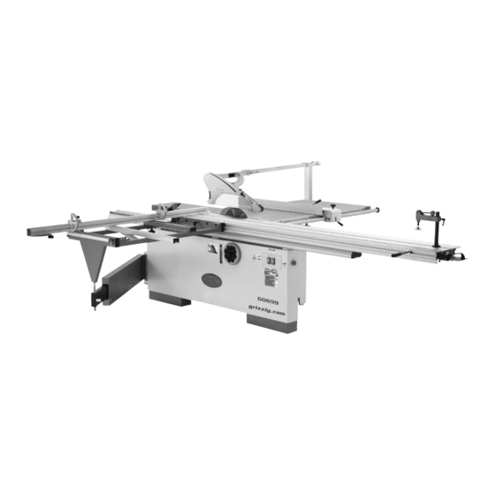
- Page 1 MODEL G0699 12" SLIDING TABLE SAW w/SCORING MOTOR OWNER'S MANUAL (For models manufactured since 5/11) WARNING: NO PORTION OF THIS MANUAL MAY BE REPRODUCED IN ANY SHAPE OR FORM WITHOUT THE WRITTEN APPROVAL OF GRIZZLY INDUSTRIAL, INC.
- Page 2 This manual provides critical safety instructions on the proper setup, operation, maintenance, and service of this machine/tool. Save this document, refer to it often, and use it to instruct other operators. Failure to read, understand and follow the instructions in this manual may result in fire or serious personal injury—including amputation, electrocution, or death.
-
Page 3: Table Of Contents
INTRODUCTION ... 2 SECTION 1: SAFETY ... 7 SECTION 2: POWER SUPPLY ... 12 SECTION 3: SETUP ... 16 SECTION 4: OPERATIONS ... 39 SECTION 5: ACCESSORIES ... 53 Table of Contents SECTION ACCESSORIES ... 55 SECTION 7: MAINTENANCE ... 61 SECTION 8: SERVICE ... -
Page 4: Introduction
INTRODUCTION Manual Accuracy Contact Info your machine may not exactly match the manual Machine Description www.grizzly.com... - Page 5 Identification Figure 1. To reduce the risk of serious injury when using this machine, read and understand this entire manual before beginning any operations.
-
Page 6: Machine Data Sheet
Machine Data Sheet Customer Service #: (570) 546-9663 · To Order Call: (800) 523-4777 · Fax #: (800) 438-5901 Weight... 1219 lbs. Width (side-to-side) x Depth (front-to-back) x Height... 139 x 133 x 45 in. Footprint (Length x Width)... 74-1/2 x 35-1/2 in. Type... - Page 7 Main Blade Size... 12 in. Main Arbor Size... 1 in. Scoring Blade Size... 4-3/4 in. (120 mm) Scoring Blade Arbor Size... 20 mm Main Blade Tilt... 0-45 deg. Main Blade Speed... 4000 RPM Scoring Blade Tilt... 0-45 deg. Scoring Blade Speed... 8000 RPM Max Depth of Cut At 90 Deg...
- Page 8 SLIDING TABLE SAW CAPACITIES MODEL G0699 12" SLIDING TABLE SAW...
-
Page 9: Section 1: Safety
SECTION 1: SAFETY For Your Own Safety, Read Instruction Manual Before Operating this Machine The purpose of safety symbols is to attract your attention to possible hazardous conditions. This manual uses a series of symbols and signal words intended to convey the level of impor- tance of the safety messages. - Page 10 DISCONNECTING POWER SUPPLY. APPROVED OPERATION. DANGEROUS ENVIRONMENTS. ONLY USE AS INTENDED. USE RECOMMENDED ACCESSORIES. CHILDREN & BYSTANDERS. REMOVE ADJUSTING TOOLS. SECURING WORKPIECE. FEED DIRECTION. FORCING MACHINERY. GUARDS & COVERS. NEVER STAND ON MACHINE. STABLE MACHINE. AWKWARD POSITIONS. UNATTENDED OPERATION. MAINTAIN WITH CARE. CHECK DAMAGED PARTS.
-
Page 11: Additional Safety Instructions For Table Saws
If normal safety pre- cautions are overlooked or ignored, serious personal injury may occur. for Table Saws RIVING KNIFE ALIGNMENT. REACHING OVER SAW BLADE. USING RIP FENCE WITH CROSSCUT FENCE. REMOVING WORKPIECES. BLADE HEIGHT. DAMAGED SAW BLADES. -
Page 12: Preventing Kickback
Below are steps you must take to avoid the most common causes of kickback: Statistics show that most common acci- dents among table saw users can be linked to kickback. Kickback is typically defined as the high-speed expulsion of stock from the table saw toward the operator. -
Page 13: Glossary Of Terms
Glossary Of Terms ARBOR. BEVEL EDGE CUT. BLADE GUARD. CROSSCUT. DADO BLADE. DADO CUT. FEATHERBOARD. KERF. KICKBACK. PARALLEL. VERY NON-THROUGHCUT. PERPENDICULAR. PUSH STICK. RABBET. RIVING KNIFE. STRAIGHTEDGE. THROUGH CUT. RIP CUT. -
Page 14: Section 2: Power Supply
SECTION 2: POWER SUPPLY Availability Electrocution, equipment damage may occur if machine is not correctly grounded and connected to the power supply. Full-Load Current Rating Full-Load Current Rating at 220V ... 23 Amps Full-Load Current Rating at 440V .. 11.5 Amps Circuit Requirements for 220V Nominal Voltage ... -
Page 15: Grounding Instructions
Grounding Instructions For 220V operation: GROUNDED L15-30 RECEPTACLE L15-30 PLUG Figure 2. For 440V operation: Figure 3. Serious injury could occur if you connect the machine to power before completing the setup process. DO NOT connect to power until instructed later in this manual. Extension Cords (220V Only) Minimum Gauge Size ...8 AWG Maximum Length (Shorter is Better)...50 ft. - Page 16 440V Conversion To rewire the Model G0699 for 440V opera- tion: Figure 4 Figure 4. Figure 5 Electrical Cabinet Wiring Diagram Page 73 Figure 5. Note: Although the two 220V relays look sim- ilar, they are not the same models. However, the two 440V relays are the same models and can be installed in either position.
- Page 17 Correcting Phase Polarity If this machine is wired out-of-phase, the blades will spin in the wrong directions. If you attempt a cutting operation with the blades spinning backward, the workpiece could be thrown aggressively from the table during the cutting operation. This could result in death or serious personal injury.
-
Page 18: Section 3: Setup
SECTION 3: SETUP This machine presents serious injury hazards to untrained users. Read through this entire manu- al to become familiar with the controls and opera- tions before starting the machine! Wear safety glasses dur- ing the entire setup pro- cess! This machine and its com- ponents are very heavy. - Page 19 Inventory Note: If you can't find an item on this list, check the mounting location on the machine or examine the packaging materials carefully. Occasionally we pre-install certain components for shipping purposes. Crate 1: (Figure 8) Figure 8.
- Page 20 Hardware (Not Shown) Crate 2: (Figure 9) Figure 9. SUFFOCATION HAZARD! Immediately discard all plas- tic bags and packing materi- als to eliminate choking/suf- focation hazards for children and animals.
-
Page 21: Hardware Recognition Chart
Hardware Recognition Chart... - Page 22 Cleanup Before cleaning, gather the following: Basic steps for removing rust preventative: Steps 2–3 Gasoline or products with low flash points can explode or cause fire if used to clean machin- ery. Avoid cleaning with these products. Many cleaning solvents are toxic if concentrat- ed amounts are inhaled.
-
Page 23: Site Considerations
Site Considerations Weight Load Machine Data Sheet Space Allocation See below for required space allocation. Children or untrained people may be seriously injured by this machine. Only install in an access restricted location. Figure 10. Physical Environment Electrical Installation Lighting... -
Page 24: Lifting & Placing
Lifting & Placing The Model G0699 is a heavy machine. Serious personal injury may occur if safe moving methods are not used. To be safe, get assistance and use power equipment to move the shipping crate and remove the machine from the crate. - Page 25 Figure 13. Figure 14 Figure 14. Figure 12 Figure 13 Figure 15. Tip: For a quick spacing gauge, use a 3mm hex wrench to set the correct spacing between the riving knife and the blade, as shown in Figure 16. Figure 16.
- Page 26 Figure 17 Figure 17. NOTICE The sliding table is heavy, so you must get help lifting it during the installation pro- cess. We recommend two strong people lift the sliding table and an additional person help position the T-bolts into the mounting holes as the table is lowered.
- Page 27 Figure 21. Important: As you align the sliding table parallel with the main saw blade in the next steps, the locating cap screw shown in Figure 22 must remain against the right side of the frame before securing the sliding table in place.
- Page 28 Figure 24 Figure 24. Figure 25 Figure 25. Figure 26. Steps 18–19 Figure 27. Figure 26 Figure 22 Page 24 Figure 27...
- Page 29 Figure 28 Figure 28. Figure 29 Figure 29. 28–29 Figure 30 Figure 30. Steps 30–32 Figures...
- Page 30 Figure 31. Figure 32 Figure 32. Figure 31 Step 35 Figure 33. Figure 34. Figure Figure 34...
- Page 31 The rip fence stop screws keep the fence from moving forward and slipping off the fence body, which could draw your hands and arms into the spinning blade during operation. Always keep these stop screws properly installed. Figure 35 Figure 35. Figure 36.
- Page 32 NOTICE The rip fence body will scratch the table and rear extension wing surfaces if the ride height is not adjusted correctly. Note: The goal of the adjustments in the next step is to make the rip fence body ride height as close to and even with the table and extension wing surfaces without touching or scratching them.
- Page 33 When properly positioned, the rail stop ring prevents the rip fence from contacting the saw blade. If this happens during cutting operations, flying metal debris could cause serious personal injury. Always make sure the rail stop ring is secured in the proper position before beginning operations.
- Page 34 Vertical Adjustment: Figure 44 Figure 46 Figure 44. Figure 45 Figure 46. Figure 47 Figure 45. Figure 47.
- Page 35 Figure 48. Figure 48 Figure 49. Figure 50. Figure 49 Figure 49 Figure 50 Steps 57–58...
-
Page 36: Dust Collection
Figure 51. Figure 52 Figure 52. Dust Collection DO NOT operate the Model G0699 without an adequate dust collection system. This saw creates substantial amounts of wood dust while operating. Failure to use a dust collec- tion system can result in short and long-term respiratory illness. -
Page 37: Power Connection
Power Connection Circuit Requirements Page 12 NOTICE The Model G0699 is prewired for 220V. If you plan to operate the machine at 440V, the two overload relays on the electrical panel must be replaced and the motors must be rewired (refer to 440V Conversion on Page 14 for detailed instructions). -
Page 38: Test Run
The test run consists of verifying the follow- ing: Troubleshooting Page 64 Before starting the saw, make sure you have performed the preceding assembly and adjustment instructions, and you have read through the rest of the manual and are familiar with the various functions and safety features on this machine. - Page 39 Figure 58 Figure 58. Figure 59 Figure 59. Correcting Phase Polarity Page 15 Correct Not Correct Figure 60. Figure 60...
-
Page 40: Recommended Adjustments
Recommended Adjustments Figure 61 Factory adjustments that should be verified: Page 44 Figure 61. Page 67 Page 68 Page 70... -
Page 41: Section 4: Operations
OMMEND that you read books, review industry trade magazines, or get formal training before beginning any projects. Regardless of the content in this section, Grizzly Industrial will not be held liable for accidents caused by lack of training. Operation Overview this... -
Page 42: Safety Precautions
Safety Precautions SAFETY Please follow these safety precautions EVERY time you use your saw: Machine Controls 62–66 Main Blade ON/OFF Buttons: Scoring Blade ON/OFF Buttons: STOP Button: Figure 62. Blade Tilt Handwheel & Lock Knob: Blade Tilt Scale: Figure 63. - Page 43 Blade Elevation Handwheel & Lock Knob: Figure 64. Sliding Table Lock Lever: Figure 65. Rip Fence Clamp Lever: Rip Fence Lock Lever: Micro-Adjust Knob: Micro-Adjust Lock Knob: Figure 66.
-
Page 44: Workpiece Inspection
Workpiece Inspection Before cutting, inspect all workpieces for the following: Material Type: Foreign Objects: Large/Loose Knots: Wet or "Green" Stock: Excessive Warping: Minor Warping: Non-Through and Through Cuts Non-Through Cuts Through Cuts Safety precautions and instructions for each type of cut are located on the following pages: Page 48 Page 50... -
Page 45: Changing Main Blade
Changing Main Blade Tools Needed To change the main blade: Figure 67. Before proceeding with the next steps, wear leather gloves to protect your hands when handling the saw and scoring blades. Figure 68 Figure 68. Figure 67... -
Page 46: Riving Knife Alignment
Riving Knife Alignment The riving knife prevents the kerf from closing behind the blade and binding the workpiece, which could cause kickback. You MUST always have the riving knife properly installed and positioned before beginning cutting operations. Tools Needed To align the riving knife: Figure 69 Figure 69. - Page 47 Alignment Zone Figure 71 Alignment Zone, Figure 72 Alignment Zone Step 8 Figure 73 Figure 71. Alignment Zone Mounting Block Figure 72. Figure 73. Steps 6–7...
-
Page 48: Adjusting & Replacing Scoring Blade
Adjusting & Replacing Scoring Blade Figure 74 Figure 74. NOTICE To make sure that the scoring blade kerf is the same as the main blade kerf, you will need to adjust the scoring blade as instructed in this procedure whenever the dimensions of the main blade change. - Page 49 Adjusting Scoring Blade Tools Needed To adjust the scoring blade position: Horizontal Adjustment: Figure 76. Vertical Adjustment: Figure 77. Figure Figure...
-
Page 50: Rip Cutting With Sliding Table
Rip Cutting Figure 78 Figure 78. Figure 79 Figure 79. Use the hold-down and the end shoe to hold down the workpiece ends to prevent it from raising up, which could cause kickback. Rip Cutting With Sliding Table Squaring Crosscut Fence to Blade Page 70 Note: The fence can be mounted in the for-... - Page 51 Steps 3–5 Figure 78 Rip Cutting With Rip Fence Figure 81 Figure 81. Figure 82 Figure 82. Figure 83 Figure 83.
-
Page 52: Crosscutting Full Size Panels
Crosscutting Figure 86 Figure 84 Figure 86. Crosscutting Full Size Panels Figure 84. Squaring Crosscut Fence to Blade Page 70 Figure 85 Figure 87 Figure 85. Figure 87. - Page 53 Figure 88 Figure 88. Steps 3–5 Note: Extend the crosscut fence slide if the workpiece is more than 74". Crosscutting Smaller Panels Size Panels Figure 85 Crosscutting Using Rip Fence as a Cut-Off Gauge Full Size Panels When using the rip fence with the cross- cut fence, the rip fence must be positioned behind the front edge of the blade to prevent the workpiece from binding and causing a...
-
Page 54: Miter Cutting
Miter Cutting To perform a miter cut: Figure 90. Figure 91 Figure 91. Figure 90 Figures 90–91... -
Page 55: Section 5: Accessories
Only use recom- mended accessories for this machine. NOTICE Refer to the newest copy of the Grizzly Catalog for other accessories available for this machine. - Page 56 Cyclone Dust Collectors G0440—2 HP, 1354 CFM @ 2.5" SP G0441—3 HP, 1654 CFM @ 2.0" SP G0443—1 ⁄ HP, 1025 CFM @ 2.6" SP Figure 95. T23037—Scoring Blade Replacement Figure 96. G7581—Superbar G7582—Master Plate Figure 97. H8029—5 Piece Safety Kit Figure 98.
-
Page 57: Section 6: Shop-Made Safety
SECTION 6: SHOP-MADE SAFETY ACCESSORIES Push Sticks Figure 99 SIZING: MATERIAL: SANDING: ⁄ " Grid Figure 99... - Page 58 Figure 99 Using a Push Stick Figure 100 Supporting Feeding Figure 100. Feeding: Supporting: Figure 100...
-
Page 59: Push Blocks
Push Blocks Push Stick Prohibition Using a Push Block Zone Supporting Figure Feeding Figure 102. CAUTION: Making a Push Block Figure 101 CAUTION: ⁄ " Grid Figure 103... - Page 60 Using a Push Block Page 57 Figure 104 Push Stick Prohibition Zone Figure 104. Figure 104 Making a Narrow-Rip Push Block for an Auxiliary Fence Figure 103, Figure 105. Note: We recommend cutting the hardwood board oversize, then jointing and planing it to the correct size to make sure the board is square and flat.
-
Page 61: Using The Auxiliary Fence And Push Block
Step 2 Figure 107 Figure 107. Figure 108. Figure 109 Figure 109. Tip: Try using cyanoacrylate type wood glue or small wood screws to secure the lip to the push block base Using the Auxiliary Fence and Push Block Figure 110 Figure Figure 110. - Page 62 Figure 111. Figure 112 Figure 112 Turn the saw OFF and allow the blade to come to a complete stop before removing the cut-off piece. Failure to follow this warn- ing could result in serious personal injury.
-
Page 63: Section 7: Maintenance
SECTION 7: MAINTENANCE Always disconnect power to the machine before performing maintenance. Failure to do this may result in serious person- al injury. Schedule Ongoing Check: Weekly Maintenance: Page 63 Monthly Check: Every 6-12 Weeks: Page 62 Page 63 Cleaning Unpainted Cast Iron Section 5: Accessories Page 53... - Page 64 Important: The position of the four upper lock nuts were set at the factory so that the cast iron table is square with the saw blade from side to side and back to front. DO NOT change the position of these lock nuts (see Figure 113).
- Page 65 Leadscrews Figures 115–116 Accessories Page 53 Figure 115. Figure 116. Sliding Table Ways Figure 117 Figure 117. Replacing Main Table Figure 118 Figure 118.
-
Page 66: Section 8: Service
SECTION 8: SERVICE Troubleshooting Motor & Electrical Page 42 Page 66... -
Page 67: Operation
Symptom Possible Cause Operation Symptom Possible Cause Possible Solution Page 66 Page 15 Possible Solution Pages 68 & 71 Page 47 Page 68 Page 70 Page 71 Page 71 Page 67 Page 71 Page... -
Page 68: Belt Service
Belt Service Removing Main Table Replacing Main Table Note: Replace the main motor V-belts as a matched set so that they will wear evenly. Main Motor V-Belts Figure 119 Figure 119. Figure 120 Page 62 Page 63 Figure 120. -
Page 69: Calibrating Blade Tilt
Scoring Motor Ribbed V-Belt To replace the scoring motor ribbed V-belt: Figure 121 Note: It takes considerable upward pressure against the spring to raise the motor. Figure 121. Calibrating Blade Tilt Tools Needed To calibrate the tilt stop nuts: Figure 122 Figure 122. -
Page 70: Adjusting Sliding Table Parallelism
Figure 123. Adjusting Sliding Table Parallelism Tools Needed To check and adjust the sliding table parallel- ism: Figure 123 Figure 124. Step 4 Step Figure 124... - Page 71 Note: Access two of the hex nuts by remov- ing the access panels on both sides of the frame, and the middle hex nut through the 5" dust port gap in the cabinet side. Figure 125. Figure 125 Steps 5, 6...
-
Page 72: Squaring Crosscut Fence To Blade
Squaring Crosscut Fence to Blade Figure 126 Figure 126. Tool Needed To adjust the 90° stop bolts: Parallel Adjustment Figure 127 Figure 127. Sliding Table Page 68 Figure 127 Steps 3–4 Steps 3–5... -
Page 73: Adjustments Rip Fence
Rip Fence Adjustments Height Above Table Tools Needed To adjust the rip fence height above the table: Figure 128 Figure 128. Parallelism To Blade Tool Needed To adjust the rip fence parallel to the main blade: Calibrating Rip Fence Scale Tool Needed To calibrate the rip fence scale: Figure 129. -
Page 74: Section 9: Wiring & Electrical
SECTION 9: WIRING & ELECTRICAL Wiring Safety Instructions SHOCK HAZARD. MODIFICATIONS. WIRE CONNECTIONS. CIRCUIT REQUIREMENTS. The photos and diagrams included in this section are best viewed in color. You can view these pages in color at www.grizzly.com. WIRE/COMPONENT DAMAGE. MOTOR WIRING. CAPACITORS/INVERTERS. EXPERIENCING DIFFICULTIES. -
Page 75: Electrical Cabinet Wiring Diagram
220V Electrical Cabinet Wiring Diagram Page 75 Page 75 READ ELECTRICAL SAFETY ON PAGE 72! -
Page 76: Component Wiring Diagrams
Component Wiring Diagrams Page 73 Page 73 READ ELECTRICAL SAFETY ON PAGE 72! -
Page 77: Main & Scoring Motor Wiring Diagrams
Main & Scoring Motor Wiring Diagrams Page 73 Page 73 READ ELECTRICAL SAFETY ON PAGE 72! -
Page 78: Electrical Component Photographs
Electrical Component Photographs Figure 132. Figure 130. Figure 133. Figure 131. Figure 134. READ ELECTRICAL SAFETY ON PAGE 72! -
Page 79: Section 10: Parts
SECTION 10: PARTS Cabinet Body... - Page 80 Cabinet Body Parts List REF PART # DESCRIPTION P06990001 ELECTRICAL PANEL GASKET PB31M HEX BOLT M10-1.5 X 40 PN02M HEX NUT M10-1.5 P06990004 MACHINE FRAME P06990005 TABLE SIDE MOUNTING PLATE PCAP26M CAP SCREW M6-1 X 12 PLW03M LOCK WASHER 6MM PW03M FLAT WASHER 6MM PFN02M...
- Page 81 Tables REF PART # DESCRIPTION PLW06M LOCK WASHER 10MM PBHS09M BUTTON HD CAP SCR M6-1 X 12 P06990110 SAW TABLE ANGLE INSERT P06990111 ALL-THREAD STUD M16-2 X 100 PLN07M LOCK NUT M16-2 P06990113 TABLE MOUNT SPACER 16MM PN13M HEX NUT M16-2...
-
Page 82: Main Blade Trunnion & Motor
Main Blade Trunnion & Motor... - Page 83 Main Blade Trunnion & Motor Parts List REF PART # DESCRIPTION PCAP03M CAP SCREW M5-.8 X 8 PLW01M LOCK WASHER 5MM PW02M FLAT WASHER 5MM PCAP26M CAP SCREW M6-1 X 12 PLW03M LOCK WASHER 6MM PCAP24M CAP SCREW M5-.8 X 16 P06990207 ANGLE PLATE PW02M...
-
Page 84: Main Blade Arbor
REF PART # DESCRIPTION P06990301 PBHS10M BUTTON HD CAP SCR M10-1.5 X 25 PLW06M LOCK WASHER 10MM PB01M HEX BOLT M10-1.5 X 30 P06990305 RIVING KNIFE FLAT WASHER 10MM P06990306 RIVING KNIFE P06990307 FRONT RIVING KNIFE BRACKET PK34M KEY 5 X 5 X 20 309A P06990309A RIVING KNIFE BRACKET ASSEMBLY P06990309... -
Page 85: Tilt & Elevation Handwheels
Tilt & Elevation Handwheels... - Page 86 Tilt & Elevation Handwheels Parts List REF PART # DESCRIPTION P06990401 LOCK KNOB M10-1.5 PW04M FLAT WASHER 10MM P06990403 HANDWHEEL FLAT WASHER 10MM P06990404 TILT HANDWHEEL ASSEMBLY PK25M KEY 7 X 7 X 20 406A P06990406A HANDWHEEL SHAFT ASSEMBLY P06990406 HANDWHEEL SHAFT P06990407 BEARING WASHER...
-
Page 87: Scoring Blade Arbor & Motor
Scoring Blade Arbor & Motor... - Page 88 Scoring Blade Arbor & Motor Parts List REF PART # DESCRIPTION PB49M HEX BOLT M12-1.75 X 20 P06990502 SCORING BLADE ARBOR FLANGE P06990503 SCORING BLADE ARBOR P6003LLB BALL BEARING 6003LLB PR54M INT RETAINING RING 15MM PR21M INT RETAINING RING 35MM P06990507 ARBOR HOUSING PW03M...
-
Page 89: Scoring Blade Adjustment System
Scoring Blade Adjustment System REF PART # DESCRIPTION PCAP14M CAP SCREW M8-1.25 X 20 PW01M FLAT WASHER 8MM P06990603 HORIZONTAL ADJUSTMENT SHAFT P06990604 ECCENTRIC SHAFT PLN03M LOCK NUT M6-1 P06990606 BELLEVILLE DISC SPRING 6MM P06990607 COMPRESSION SPRING P06990608 PIVOT ARM PW03M FLAT WASHER 6MM REF PART #... -
Page 90: Swing Arm
REF PART # DESCRIPTION P06990701 SWING ARM MAGNET P06990702 CROSSCUT PIVOT STUD M20-2.5 PN28M HEX NUT M20-2.5 P06990704 END PLUG 40 X 120MM PSS74M SET SCREW M8-1.25 X 35 P06990706 MAGNET HOLDER P06990707 SLIDING TUBE PB09M HEX BOLT M8-1.25 X 20 PN03M HEX NUT M8-1.25 PBHS11M... -
Page 91: Crosscut Table
REF PART # DESCRIPTION P6201ZZ BALL BEARING 6201ZZ P06990802 SPACER P06990803 ROLLER P06990804 LARGE FRAME END PLUG 805V2 P06990805V2 CROSSCUT TABLE FRAME V2.05.11 P06990806 T-NUT M8-1.25 P06990807 KNOB BOLT M8-1.25 X 25 PWF08M FENDER WASHER 8MM P06990809 MEDIUM FRAME END PLUG P06990810 SMALL FRAME END PLUG P06990811... -
Page 92: Crosscut Fence
REF PART # DESCRIPTION P06990806 T-NUT M8-1.25 P06990902 STOP BRACKET P06990903 KNOB BOLT M8-1.25 X 40 P06990904 FLIP STOP PIVOT SHAFT P06990905 FLIP STOP PSS16M SET SCREW M8-1.25 X 10 PLN05M LOCK NUT M10-1.5 P06990908 EXTENSION CONNECTOR P06990909 EXTENSION FENCE P06990910 EXTENSION FENCE END PLATE PHTEK15M... -
Page 93: Rip Fence
Rip Fence... -
Page 94: Rip Fence Parts List
Rip Fence Parts List PART # DESCRIPTION 1001 P06991001 FENCE SLIDE LOCK KNOB 1002 P06991002 LOCK KNOB HANDLE 1003A P06991003A RIP FENCE CASTING ASSEMBLY 1003V2 P06991003V2 RIP FENCE CASTING V2.05.11 1005 P06991005 CASTING SUPPORT BAR 1006 P06991006 MICRO-ADJUST KNOB BOLT 1007V2 P06991007V2 FENCE RAIL BRACKET V2.05.11 1008... -
Page 95: Sliding Table
PART # DESCRIPTION 1121 PN09M HEX NUT M12-1.75 1122 PLW05M LOCK WASHER 12MM 1123 PW06M FLAT WASHER 12MM 1124 P06991124 T-BOLT M12-1.75 X 40 1125V2 P06991125V2 SLIDING TABLE BASE 3200MM V2.05.11 1127 PFH26M FLAT HD SCR M6-1 X 30 1126V2 P06991126V2 BASE LEFT SIDE COVER V2.05.11 1128V2... -
Page 96: Blade Guard
REF PART # DESCRIPTION 1201 PCAP64M CAP SCREW M10-1.5 X 25 1202 P06991202 MAIN BLADE GUARD 2-PC 1203 PLN05M LOCK NUT M10-1.5 1204 PHTEK34M TAP SCREW M3 X 16 1206 P06991206 PIVOT SCREW M5-.8 X 10 1207 P06991207 PIVOT SLEEVE 1208 P06991208 SCORING BLADE GUARD 2-PC Blade Guard... -
Page 97: Electrical Cabinet
Electrical Cabinet REF PART # DESCRIPTION 1301 P06991301 ELECTRICAL CABINET BACK PLATE 1302 P06991302 TERMINAL BAR 3-POST 1303 P06991303 TERMINAL BAR 6-POST 1304 P06991304 CONTACTOR SDE MA-30 220V 1305 P06991305 CONTACTOR SDE MA-09 220V 1306 P06991306 FUSE HOLDER REF PART # DESCRIPTION 1307 P06991307 FUSE 2A... - Page 98 REF PART # DESCRIPTION 1401 P06991401 TOOL BOX 1402 P06991402 SCORING ARBOR WRENCH 1403 PWR1719 WRENCH 17/19MM 1404 P06991404 WRENCH 30MM Accessories REF PART # 1405 P06991405 1406 P06991406 1407 P06991407 1408 P06991408 DESCRIPTION T-HANDLE WRENCH 8MM PUSH STICK HOLD-DOWN ASSEMBLY EDGE SHOE ASSEMBLY...
-
Page 99: Front Machine Labels
MUST maintain the original location and readability of the labels on the machine. If any label is removed or becomes unreadable, REPLACE that label before using the machine again. Contact Grizzly at (800) 523-4777 or www.grizzly.com to order new labels. -
Page 100: Rear & Blade Guard Machine Labels
EYE/LUNG HAZARD LABEL 1510 P06991510 MODEL NUMBER LABEL REF PART # DESCRIPTION 1511 G8589 GRIZZLY OVAL NAMEPLATE 1512 PPAINT-11 GRIZZLY PUTTY TOUCH-UP PAINT 1513 PPAINT-1 GRIZZLY GREEN TOUCH-UP PAINT 1514 PLABEL-14 ELECTRICITY LABEL 1515 PLABEL-34C PREWIRED 220V LABEL 1516 P06991516... -
Page 101: Warranty Card
The following information is given on a voluntary basis. It will be used for marketing purposes to help us develop better products and services. Of course, all information is strictly confidential. Note: We never use names more than 3 times. _____________________________________________________________________ _________________________________________________________________________________ _________________________________________________________________________________... -
Page 103: Warranty And Returns
WARRANTY AND RETURNS... - Page 104 ® Buy Direct and Save with Grizzly – Trusted, Proven and a Great Value! ~Since 1983~ Visit Our Website Today For Current Specials! ORDER 24 HOURS A DAY! 1-800-523-4777...
Need help?
Do you have a question about the G0699 and is the answer not in the manual?
Questions and answers