Grizzly G0690 Owner's Manual
10" cabinet table saw
w/riving knife
Hide thumbs
Also See for G0690:
- Owner's manual (92 pages) ,
- Parts list (12 pages) ,
- Owner's manual (92 pages)
Table of Contents
Advertisement
Quick Links
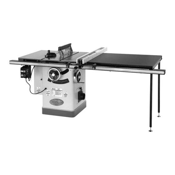
MODEL G0690/G0691
10" CABINET TABLE SAW
w/RIVING KNIFE
OWNER'S MANUAL
Model G0690
Model G0691
232857
COPYRIGHT © NOVEMBER, 2008 BY GRIZZLY INDUSTRIAL, INC. REVISED NOVEMBER, 2015 (WK)
WARNING: NO PORTION OF THIS MANUAL MAY BE REPRODUCED IN ANY SHAPE
OR FORM WITHOUT THE WRITTEN APPROVAL OF GRIZZLY INDUSTRIAL, INC.
(FOR MODELS MANUFACTURED SINCE 9/11) #BL11376 PRINTED IN CHINA
V2.11.15
Advertisement
Table of Contents

Related Manuals for Grizzly G0690


Summary of Contents for Grizzly G0690
- Page 1 Model G0690 Model G0691 232857 COPYRIGHT © NOVEMBER, 2008 BY GRIZZLY INDUSTRIAL, INC. REVISED NOVEMBER, 2015 (WK) WARNING: NO PORTION OF THIS MANUAL MAY BE REPRODUCED IN ANY SHAPE OR FORM WITHOUT THE WRITTEN APPROVAL OF GRIZZLY INDUSTRIAL, INC. (FOR MODELS MANUFACTURED SINCE 9/11) #BL11376 PRINTED IN CHINA...
- Page 2 This manual provides critical safety instructions on the proper setup, operation, maintenance, and service of this machine/tool. Save this document, refer to it often, and use it to instruct other operators. Failure to read, understand and follow the instructions in this manual may result in fire or serious personal injury—including amputation, electrocution, or death.
-
Page 3: Table Of Contents
Manual Accuracy ........... 2 Featherboards ..........50 Identification ........... 3 Push Sticks ..........53 G0690 Machine Data Sheet ......4 Push Blocks ..........54 G0691 Machine Data Sheet ......7 Narrow-Rip Auxiliary Fence & Push Block .. 55 Outfeed & Support Tables ......57 SECTION 1: SAFETY ........ -
Page 4: Introduction
Manufacture Date and Serial Number from the machine ID label (see below). This information is required for us to provide proper tech support, and it helps us determine if updated documenta- tion is available for your machine. Manufacture Date Serial Number Model G0690/G0691 (Mfd. 6/15+) -
Page 5: Identification
Keep hands out of the line of saw blade. d) Use a push-stick when required. e) Pay particular attention to instructions on reducing risk of kickback. f) Do not perform any operation freehand. g) Never reach around or over saw blade. Model G0690/G0691 (Mfd. 6/15+) -
Page 6: G0690 Machine Data Sheet
MACHINE DATA SHEET Customer Service #: (570) 546-9663 · To Order Call: (800) 523-4777 · Fax #: (800) 438-5901 MODEL G0690 10" 3HP 220V CABINET TABLE SAW WITH RIVING KNIFE Product Dimensions: Weight................................507 lbs. Width (side-to-side) x Depth (front-to-back) x Height................62 x 41 x 40 in. - Page 7 The information contained herein is deemed accurate as of 11/29/2015 and represents our most recent product specifications. Model G0690 PAGE 2 OF 3 Due to our ongoing improvement efforts, this information may not accurately describe items previously purchased. Model G0690/G0691 (Mfd. 6/15+)
- Page 8 Recessed Screw Holding Table Insert Included 10" x 40T Carbide-Tipped Blade Accessories Recommended: T24862 Long Rail Kit for G0690 The information contained herein is deemed accurate as of 11/29/2015 and represents our most recent product specifications. Model G0690 PAGE 3 OF 3 Due to our ongoing improvement efforts, this information may not accurately describe items previously purchased.
-
Page 9: G0691 Machine Data Sheet
The information contained herein is deemed accurate as of 11/29/2015 and represents our most recent product specifications. Model G0691 PAGE 1 OF 3 Due to our ongoing improvement efforts, this information may not accurately describe items previously purchased. Model G0690/G0691 (Mfd. 6/15+) - Page 10 The information contained herein is deemed accurate as of 11/29/2015 and represents our most recent product specifications. Model G0691 PAGE 2 OF 3 Due to our ongoing improvement efforts, this information may not accurately describe items previously purchased. Model G0690/G0691 (Mfd. 6/15+)
- Page 11 The information contained herein is deemed accurate as of 11/29/2015 and represents our most recent product specifications. Model G0691 PAGE 3 OF 3 Due to our ongoing improvement efforts, this information may not accurately describe items previously purchased. Model G0690/G0691 (Mfd. 6/15+)
-
Page 12: Section 1: Safety
Everyday ery. Never operate under the influence of drugs or eyeglasses are NOT approved safety glasses. alcohol, when tired, or when distracted. -10- Model G0690/G0691 (Mfd. 6/15+) - Page 13 EXPERIENCING DIFFICULTIES. If at any time debris. Make sure they are properly installed, you experience difficulties performing the intend- undamaged, and working correctly BEFORE ed operation, stop using the machine! Contact our operating machine. Technical Support at (570) 546-9663. -11- Model G0690/G0691 (Mfd. 6/15+)
-
Page 14: Additional Safety For Table Saws
Never push blocks whenever possible. In event of an accident, these will often take damage that would cut materials not intended for this saw. have occurred to hands/fingers. -12- Model G0690/G0691 (Mfd. 6/15+) -
Page 15: Preventing Kickback
Making a deep area being struck by the flying stock, it is non-through cut will greatly increase the often the case that the operator’s hands are chance of kickback. pulled into the blade during kickback. -13- Model G0690/G0691 (Mfd. 6/15+) -
Page 16: Glossary Of Terms
The following is a list of common definitions, terms and phrases used throughout this manual as they relate to this table saw and woodworking in general. Become familiar with these terms for assembling, adjusting or operating this machine. Your safety is VERY important to us at Grizzly! Non-Through Cut: A cut in which the blade does Arbor: Rotating metal shaft to which saw blade not cut through the top of the workpiece. -
Page 17: Section 2: Power Supply
To reduce the risk of these hazards, avoid over- loading the machine during operation and make sure it is connected to a power supply circuit that meets the specified circuit requirements. -15- Model G0690/G0691 (Mfd. 6/15+) -
Page 18: Grounding Instructions
Minimum Gauge Size ......12 AWG Maximum Length (Shorter is Better)..50 ft. all local codes and ordinances. -16- Model G0690/G0691 (Mfd. 6/15+) -
Page 19: Section 3: Setup
Wrench or Socket 10mm ......1 injuries, crushing injuries, • Wrench 14mm ..........1 or property damage. • Adjustable Wrench ........1 To reduce your risk of serious injury, read this entire manual BEFORE using machine. -17- Model G0690/G0691 (Mfd. 6/15+) -
Page 20: Hardware Recognition Chart
Hardware Recognition Chart -18- Model G0690/G0691 (Mfd. 6/15+) -
Page 21: Inventory
If you cannot find an item on this list, care- fully check around/inside the machine and packaging materials. Often, these items get lost in packaging materials while unpack- ing or they are pre-installed at the factory. Figure 5. Component inventory. -19- Model G0690/G0691 (Mfd. 6/15+) -
Page 22: Fence Inventory G0690
" ....... 1 Legs ............2 Figure 6. Inventory needed to install the fence Figure 7. Inventory needed to install the fence on the Model G0690. on the Model G0691. Hardware and Tools (Not Shown) Hardware and Tools (Not Shown) Cap Screws M6-1 x 16 (Front Rail/Tube) .. -
Page 23: Cleanup
Figure 8. T23692 Orange Power Degreaser. Repeat Steps 2–3 as necessary until clean, then coat all unpainted surfaces with a quality metal protectant to prevent rust. -21- Model G0690/G0691 (Mfd. 6/15+) -
Page 24: Site Considerations
Door Door Access Access Swing at 90º Swing at 90º Door Door Swing at 90º Swing at 90º 45½" 45½" 45½" 45½" Min. 30" Min. 30" Min. 30" Min. 30" Figure 9. Minimum working clearances. -22- Model G0690/G0691 (Mfd. 6/15+) -
Page 25: Assembly
14mm wrench (see Figure 12). Assembly steps are the same for the Model G0690 and G0691 except where noted. Assembly consists of installing minor components, the exten- sion wings, front and rear rails, extension table, and the legs (Model G0691 only). - Page 26 (4) M8-1.25 x 30 cap screws, 8mm lock washers, and 8mm flat washers removed in Step 6 (Figure 15). Figure 17. Masking tape location for adjusting the extension wing down. Figure 15. Extension wings installed. -24- Model G0690/G0691 (Mfd. 6/15+)
- Page 27 Figure 18. Front rail installed (Model G0690 shown in Figure 21. shown). 11. G0690 ONLY: Install the 62" front rail rectan- gular tube onto the 50" front rail with (3) M6-1 x 16 cap screws, 6mm flat washers, and 6mm lock washers, as shown in Figure 19.
- Page 28 T-slots (see Figure 22), so the miter gauge will slide smoothly when installed later. Figure 24. Adjusting Model G0690 extension table flush with extension wing and table. G0691 Extension Table While an assistant holds the extension table between the front and rear rails, fasten the extension table to the rails with (6) M8-1.25 x...
-
Page 29: Magnetic Switch
Put on a pair of heavy leather gloves and use the included arbor wrenches to tighten the arbor nut (turn clockwise to tighten), as shown in Figure 29. Figure 27. Fence installed on rails. -27- Model G0690/G0691 (Mfd. 6/15+) - Page 30 Pointer Window Fence Figure 31. Aligning rail tape with scale pointer. Miter Slot On the Model G0690, if you move the pointer win- Blade Fence is dow to the right side of the fence, you may have Parallel to to trim the last two inches of the scale so it will not Miter Slot, protrude past the end of the fence tube.
- Page 31 Proceed to Give the spreader an upward tug to verify that "Checking Alignment" on Page 68 to deter- it is locked. mine if the spreader/riving knife is bent. -29- Model G0690/G0691 (Mfd. 6/15+)
-
Page 32: Dust Collection
After you have completed all previous setup instructions and circuit requirements, the machine is ready to be connected to the power supply. DO NOT operate the Model G0690 or G0691 without an adequate dust collection system. To avoid unexpected startups or property dam-... -
Page 33: Test Run
Adjustments that should be verified: Insert the switch disabling pin through the green ON button, as shown in Figure 38. Blade Tilt Stop Accuracy (Page 65). Miter Slot Parallel to Blade (Page 67). Spreader/Riving Knife Alignment (Page 68). -31- Model G0690/G0691 (Mfd. 6/15+) -
Page 34: Section 4: Operations
Regardless of the content in this section, Grizzly Industrial will not be held liable for Stops the machine immediately after the cut accidents caused by lack of training. -
Page 35: Basic Controls
Fence Lock Blade Tilt Lock Blade Height Lock Blade Height Blade Tilt Handwheel Handwheel Figure 42. Example of a through cut (blade Figure 40. Basic table saw controls. guard not shown for illustrative clarity). -33- Model G0690/G0691 (Mfd. 6/15+) -
Page 36: Workpiece Inspection
Excessive Warping: Workpieces with exces- sive cupping, bowing, or twisting are danger- ous to cut because they are unstable and may move unpredictably when being cut. • Minor Warping: Slightly cupped workpieces Figure 43. Ripping blade. can be safely supported with cupped side facing the table or fence; however, work- pieces supported on the bowed side will rock during the cut, which could cause kickback. -34- Model G0690/G0691 (Mfd. 6/15+) - Page 37 The blade angle is adjustable on the hub, and the width of the dado cut is controlled by the angle setting of the blade. Flat Figure 45. Combination blade. Figure 47. Stacked dado blade. -35- Model G0690/G0691 (Mfd. 6/15+)
-
Page 38: Blade Installation
DO NOT overtighten. Use the arbor wrenches to loosen and remove the arbor nut, flange, and blade. Note: The arbor nut has right hand threads; turn it counterclockwise to loosen. -36- Model G0690/G0691 (Mfd. 6/15+) -
Page 39: Blade Guard Assembly
It also acts as a barrier behind the blade to shield hands from being pulled into the blade if a kick- back occurs. -37- Model G0690/G0691 (Mfd. 6/15+) - Page 40 Enabling Pawls To enable the pawls, lift up on each pawl and move them outward and down until they both touch the table surface, as shown in Figure 50 on Page 37. -38- Model G0690/G0691 (Mfd. 6/15+)
-
Page 41: Riving Knife
Top Distance Minimum 3mm Maximum 8mm Bottom Distance Minimum 3mm Maximum 8mm Figure 53. Allowable top and bottom distances between riving knife and blade. -39- Model G0690/G0691 (Mfd. 6/15+) -
Page 42: Ripping
Failure to do this could devices. result in serious personal injury or death. Plug the saw into the power source, turn it ON, and allow it to reach full speed. -40- Model G0690/G0691 (Mfd. 6/15+) -
Page 43: Crosscutting
Crosscutting instruc- tions. Turn OFF the saw and allow the blade to come to a complete stop before removing the cut-off piece. Failure to follow this warn- ing could result in serious personal injury -41- Model G0690/G0691 (Mfd. 6/15+) -
Page 44: Blade Tilt/Bevel Cuts
Figure 58. Example of a dado cut with a dado blade. DO NOT make through cuts with a dado blade. Dado blades are only intended for non-through cuts. Failure to heed this warning could result in serious injury. -42- Model G0690/G0691 (Mfd. 6/15+) - Page 45 ALWAYS replace the blade guard after dadoing is complete. -43- Model G0690/G0691 (Mfd. 6/15+)
- Page 46 Align the blade to cut one of the dado sides, as shown in Figure 60. Cuts 3+ Fence Workpiece Blade Cut 1 Fence Workpiece Figure 62. Additional single blade dado cuts. Figure 60. First cut for a single-blade dado. -44- Model G0690/G0691 (Mfd. 6/15+)
-
Page 47: Rabbet Cutting
ALWAYS replace the blade guard after dadoing is complete. -45- Model G0690/G0691 (Mfd. 6/15+) - Page 48 — If the workpiece is very tall, or is unstable Figure 66. Second cut to create a rabbet. when placed against the fence, lay it flat on the table and use a dado blade to perform the rabbet cut. -46- Model G0690/G0691 (Mfd. 6/15+)
-
Page 49: Resawing
⁄ ". #8 x 2" ⁄ " Wood Screw ⁄ " Assembled Resaw Barrier Figure 67. Resaw barrier. -47- Model G0690/G0691 (Mfd. 6/15+) -
Page 50: Auxiliary Fence
Auxiliary Facing the workpiece, as shown in Figure 69. Now Fence clamp the resaw barrier to the top of the table saw at both ends. Figure 68. Auxiliary fence. -48- Model G0690/G0691 (Mfd. 6/15+) - Page 51 Flip the workpiece end for end, keeping the same side against the fence, and run the workpiece through the blade. -49- Model G0690/G0691 (Mfd. 6/15+)
-
Page 52: Section 5: Shop Made Safety Accessories
Step 3 will bend without breaking. NOTICE Cut a 30º angle at one end of the board. Only Steps 1–3 are required to make a clamp-mounted featherboard. Refer to Page 52 for instructions on clamping. -50- Model G0690/G0691 (Mfd. 6/15+) - Page 53 Figure 73. Miter bar pattern. Now, proceed to Mounting Featherboard in Miter Slot on Page 52. Drill a ⁄ " hole in the center of the bar, then countersink the bottom to fit a ⁄ "-20 flat head screw. -51- Model G0690/G0691 (Mfd. 6/15+)
- Page 54 Note: The featherboard should be placed firmly enough against the workpiece to keep it against the fence but not so tight that it is difficult to feed the workpiece. -52- Model G0690/G0691 (Mfd. 6/15+)
-
Page 55: Push Sticks
⁄ " Grid increase comfort. from the blade! Figure 79. Template for a basic shop-made push stick (not shown at actual size). -53- Model G0690/G0691 (Mfd. 6/15+) -
Page 56: Push Blocks
Lip for pushing workpiece ⁄ " Grid 9"−10" Minimum Length Figure 82. Template for a shop-made push block (shown at 50% of full size). -54- Model G0690/G0691 (Mfd. 6/15+) -
Page 57: Narrow-Rip Auxiliary Fence & Push Block
Attach the handle to the base with #8 x 1 ⁄ " wood screws, and attach the lip to the base Length of Table Saw Rip Fence with cyanoacrylate type wood glue. ⁄ " Figure 83. Auxiliary fence dimensions. -55- Model G0690/G0691 (Mfd. 6/15+) - Page 58 Turn OFF the saw and allow the blade to evenly against the table and the auxiliary come to a complete stop before removing fence. the cut-off piece. Failure to follow this warn- ing could result in serious personal injury. -56- Model G0690/G0691 (Mfd. 6/15+)
-
Page 59: Outfeed & Support Tables
Crosscut Sled Support Outfeed Table Table Figure 90. Example of crosscut sled. Figure 89. Example of outfeed & support tables. -57- Model G0690/G0691 (Mfd. 6/15+) -
Page 60: Section 6: Accessories
34 lbs. serious personal injury or machine damage. To reduce this risk, only install accessories recommended for this machine by Grizzly. NOTICE Refer to our website or latest catalog for additional recommended accessories. H7583—Grizzly Tenoning Jig... - Page 61 Forrest Dado Blades T10223—Sliding Table Attachment H4756—8" x ⁄ " 24T Dado Blade Set Accessorize your G0690 or G0691 Cabinet Table T23267—8" x ⁄ " 24T 3 Pc. Set Saw with either of these attachments for the ulti- The world's finest dado blades cleancut all your mate in table saw functionality.
- Page 62 Figure 98. Model D3096 Featherboard. D4216 D4206 W1317 T20916—Zero Clearance Insert for G0690-91 Made especially for our G0690 and G0691 Table Saws. Height is easily adjustable. Special pheno- lic material. W1053 W1017 W1007 Figure 101. Dust collection accessories.
-
Page 63: Section 7: Maintenance
SECTION 7: MAINTENANCE Cleaning Always disconnect power to the machine before Cleaning the Model G0690/G0691 is relatively performing maintenance. easy. Vacuum excess wood chips and sawdust, Failure to do this may and wipe off the remaining dust with a dry cloth. -
Page 64: Lubrication
Figure 103. Trunnion slides and tilt leadscrew. Also use a wire brush and mineral spirits to clean any debris or grime off the orientation gears, then apply lithium grease to the gears with a brush. -62- Model G0690/G0691 (Mfd. 6/15+) -
Page 65: Section 8: Service
8. Motor fan rubbing on fan cover. 8. Fix/replace fan cover; replace loose/damaged fan. 9. Arbor bearings at fault. 9. Replace arbor housing bearings; replace arbor. 10. Motor bearings at fault. 10. Test by rotating shaft; grinding/loose shaft requires bearing replacement. -63- Model G0690/G0691 (Mfd. 6/15+) - Page 66 2. Blade is warped. through table saw. 3. Fence is not parallel to blade. 3. Make fence parallel to blade (Page 69). 4. Make table parallel to blade (Page 67). 4. Table top is not parallel to blade. -64- Model G0690/G0691 (Mfd. 6/15+)
-
Page 67: Blade Tilt Stops
Figure 106 points to the 0° mark on the scale. Adjust the position by loosening the button head screw, moving the indicator with your fin- gers, then tightening the screw. -65- Model G0690/G0691 (Mfd. 6/15+) - Page 68 Continue adjusting the stop bolt until it con- tacts the cabinet when the blade is at 45°, then tighten the jam nut. 45° Square Close the dust port. Blade Table Figure 109. Checking blade at 45°. -66- Model G0690/G0691 (Mfd. 6/15+)
-
Page 69: Miter Slot To Blade Parallelism
Repeat Steps 2–5 until the blade and miter slot are parallel. Tighten the table mounting cap screws in a criss-cross, alternating manner. Mounting Bolts Figure 111. Example of adjusting blade to miter slot. Figure 112. Table mounting bolts. -67- Model G0690/G0691 (Mfd. 6/15+) -
Page 70: Spreader Or Riving Knife Alignment
Hex Wrench 3mm ..........1 Hex Wrench 5mm ..........1 Table To adjust the spreader/riving knife position: Figure 113. Checking top and bottom riving knife parallelism with blade. DISCONNECT THE SAW FROM POWER! Remove the table insert. -68- Model G0690/G0691 (Mfd. 6/15+) -
Page 71: Fence Adjustments
The fence face must be square to the table in block holds the spreader/riving knife, adjust order to produce square cuts. Also, the fence the center screw. should be adjusted high enough off the table that it does not drag across the surface. -69- Model G0690/G0691 (Mfd. 6/15+) - Page 72 — If the gap is approximately ⁄ " and even from the front of the table to the back, then Place the fence approximately 4" away from no additional adjustments are necessary. the blade. -70- Model G0690/G0691 (Mfd. 6/15+)
-
Page 73: Fence Scale Calibration
The workpiece width should be exactly 12". If it is not, then adjust Figure 120. Adjusting fence with a ⁄ " offset. the indicator window to match the width of the workpiece. -71- Model G0690/G0691 (Mfd. 6/15+) -
Page 74: Miter Gauge Adjustments
(not the teeth) evenly Figure 124. Screws for adjusting miter bar in at the same time, then it is square to the miter slot. blade and the 90° stop is set correctly. No further adjustments are necessary. -72- Model G0690/G0691 (Mfd. 6/15+) -
Page 75: Belt Tension & Replacement
Close the motor access cover. Press each V-belt in the center to check belt tension. The belts are correctly tensioned when there is approximately ⁄ " deflection when they are pushed with moderate pressure, as shown in Figure 126. -73- Model G0690/G0691 (Mfd. 6/15+) -
Page 76: Section 9: Wiring
Technical Support at (570) 546-9663. The photos and diagrams included in this section are best viewed in color. You can view these pages in color at www.grizzly.com. -74- Model G0690/G0691 (Mfd. 6/15+) -
Page 77: Model G0690/G0691 Wiring Diagram
Model G0690/G0691 Wiring Diagram CHINT 220V 60HZ CHINT NCI-18 Figure 127. Magnetic switch. Ground CHINT NR2-25 TEST 98 NO 97 NO 96 NC 95 NC Figure 129. Run capacitor. Figure 128. Motor wiring. Ground Start Capacitor 200MFD 250VAC Capacitor 6-20 Plug... -
Page 78: Section 10: Parts
SECTION 10: PARTS Body 46-1 46-2 55V2 55-1 55-3V2 55-4 55-6 55-2 55-5 65V2 70 71 -76- Model G0690/G0691 (Mfd. 6/15+) - Page 79 PHLP HD SCR M5-.8 X 20 P0690069 BUTTON HD CAP SCR M5-.8 X 16 P0690036 DADO TABLE INSERT P0690070 LOCK WASHER 5MM P0690040 NAME PLATE RIVET P0690071 FLAT WASHER 5MM P0690041 SHIPPING BRACE P0690072 PUSH STICK -77- Model G0690/G0691 (Mfd. 6/15+)
-
Page 80: Trunnion
Trunnion -78- Model G0690/G0691 (Mfd. 6/15+) - Page 81 ORIENTATION PIN P0690196 RIGHT BRACKET P0690136 ROLL PIN 4 X 28 P0690197 CAP SCREW M8-1.25 X 30 P0690137 HEX BOLT M12-1.75 X 100 P0690198 FLAT WASHER 8MM P0690138 FLAT WASHER 12MM P0690199 LOCK WASHER 8MM -79- Model G0690/G0691 (Mfd. 6/15+)
- Page 82 SET SCREW M6-1 X 12 P0690218 LOCK NUT M10-1.5 P0690239 LOCK WASHER 6MM P0690219 GEAR SLEEVE P0690240 SPACER P0690220 PLATE GEAR P0690241 SPLITTER TIGHTENING CLIP P0690221 SET SCREW M6-1 X 20 P0690242 HEX BOLT M6-1 X 30 -80- Model G0690/G0691 (Mfd. 6/15+)
-
Page 83: Blade Guard
FLAT WASHER 5MM P0690356 GUARD CLAMP 335V2 P0690335V2 LOCK NUT M6-1 P0690357 PHLP HD SCR M6-1 X 35 339V2 P0690339V2 FLAT WASHER 5MM P0690358 HEX BOLT M5-.8 X 8 340V2 P0690340V2 HEX BOLT M4-.7 X 8 -81- Model G0690/G0691 (Mfd. 6/15+) -
Page 84: Miter Gauge
MITER KNOB P0690409 MITER STOP PIN KNOB P0690419 FENDER WASHER 8MM 410V2 P0690410V2 MITER STOP PIN BLOCK V2.10.15 P0690420 SET SCREW M8-1.25 X 6 P0690411 COMPRESSION SPRING P0690421 BUTTON HD CAP SCR M4-.7 X 10 -82- Model G0690/G0691 (Mfd. 6/15+) -
Page 85: Fence
P0690507 PHLP HD SCR M5-.8 X 10 P0690518 P0690508 LOCK WASHER 5MM P0690519 FENCE LOCK KNOB P0690509 INDICATOR P0690520 SET SCREW M12-1.75 X 30 P0690510 FENCE BODY P0690521 SPECIAL LOCKING NUT M12-1.75 P0690511 SET SCREW -83- Model G0690/G0691 (Mfd. 6/15+) -
Page 86: Extension Table (G0690)
P0690605 CAP SCREW M6-1 X 16 P0690613 HEX NUT M8-1.25 P0690606 LOCK WASHER 6MM 614V2 P0690614V2 TABLE BOARD V2.11.13 P0690607 FLAT WASHER 6MM P0690615 HEX BOLT M8-1.25 X 30 P0690608 HEX BOLT 5/16-18 X 1-1/2 -84- Model G0690/G0691 (Mfd. 6/15+) -
Page 87: Extension Table (G0691)
HEX BOLT M8-1.25 X 60 P0690608 HEX BOLT 5/16-18 X 1-1/2 P0691618 CAP SCREW M6-1 X 16 P0690609 LOCK WASHER 8MM P0691619 CAP SCREW M8-1.25 X 20 P0690610 FLAT WASHER 8MM P0691620 HEX BOLT M8-1.25 X 30 -85- Model G0690/G0691 (Mfd. 6/15+) -
Page 88: Labels And Cosmetics
MUST maintain the original location and readability of the labels on the machine. If any label is removed or becomes unreadable, REPLACE that label before using the machine again. Contact Grizzly at (800) 523-4777 or www.grizzly.com to order new labels. -86-... -
Page 89: Warranty Card
Would you recommend Grizzly Industrial to a friend? _____ Yes _____No Would you allow us to use your name as a reference for Grizzly customers in your area? Note: We never use names more than 3 times. _____ Yes _____No 10. - Page 90 FOLD ALONG DOTTED LINE Place Stamp Here GRIZZLY INDUSTRIAL, INC. P.O. BOX 2069 BELLINGHAM, WA 98227-2069 FOLD ALONG DOTTED LINE Send a Grizzly Catalog to a friend: Name_______________________________ Street_______________________________ City______________State______Zip______ TAPE ALONG EDGES--PLEASE DO NOT STAPLE...
-
Page 91: Warranty And Returns
WARRANTY AND RETURNS Grizzly Industrial, Inc. warrants every product it sells for a period of 1 year to the original purchaser from the date of purchase. This warranty does not apply to defects due directly or indirectly to misuse, abuse, negligence, accidents, repairs or alterations or lack of maintenance.
Need help?
Do you have a question about the G0690 and is the answer not in the manual?
Questions and answers