Table of Contents
Advertisement
Quick Links
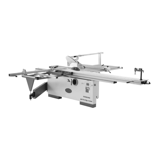
MODEL G0699
12" SLIDING TABLE SAW
w/SCORING MOTOR
OWNER'S MANUAL
(For models manufactured since 5/15)
COPYRIGHT © JUNE, 2010 BY GRIZZLY INDUSTRIAL, INC., REVISED SEPTEMBER, 2018 (MN)
WARNING: NO PORTION OF THIS MANUAL MAY BE REPRODUCED IN ANY SHAPE
OR FORM WITHOUT THE WRITTEN APPROVAL OF GRIZZLY INDUSTRIAL, INC.
#TS12139 PRINTED IN TAIWAN
V5.09.18
Advertisement
Table of Contents

Related Manuals for Grizzly G0699


Summary of Contents for Grizzly G0699
- Page 1 OWNER'S MANUAL (For models manufactured since 5/15) COPYRIGHT © JUNE, 2010 BY GRIZZLY INDUSTRIAL, INC., REVISED SEPTEMBER, 2018 (MN) WARNING: NO PORTION OF THIS MANUAL MAY BE REPRODUCED IN ANY SHAPE OR FORM WITHOUT THE WRITTEN APPROVAL OF GRIZZLY INDUSTRIAL, INC.
- Page 2 This manual provides critical safety instructions on the proper setup, operation, maintenance, and service of this machine/tool. Save this document, refer to it often, and use it to instruct other operators. Failure to read, understand and follow the instructions in this manual may result in fire or serious personal injury—including amputation, electrocution, or death.
-
Page 3: Table Of Contents
Table of Contents INTRODUCTION ..........2 SECTION SHOP-MADE SAFETY Manual Accuracy ........... 2 ACCESSORIES ..........61 Contact Info............ 2 Push Sticks ..........61 Machine Description ........2 Push Blocks ..........63 Identification ........... 3 SECTION 7: MAINTENANCE ......67 Machine Data Sheet ........4 Schedule ............ -
Page 4: Introduction
This saw can also be used as a traditional table saw for most types of through-cuts. Serial Number The Model G0699 is equipped with a scoring blade, which is a smaller blade located in front of the main blade. It makes a shallow cut in the... -
Page 5: Identification
Swing Scoring Blade ON/OFF Button Main Blade ON/OFF Button Figure 1. Model G0699 identification. For Your Own Safety Read Instruction Manual Before Operating Saw a) Wear eye protection. b) Use saw-blade guard and riving knife for every operation for which it can be used, including all through sawing. -
Page 6: Machine Data Sheet
Machine Data Sheet MACHINE DATA SHEET Customer Service #: (570) 546-9663 · To Order Call: (800) 523-4777 · Fax #: (800) 438-5901 MODEL G0699 12" SLIDING TABLE SAW WITH SCORING BLADE MOTOR Product Dimensions: Weight................................1274 lbs. Width (side-to-side) x Depth (front-to-back) x Height............... 139 x 133 x 45 in. - Page 7 The information contained herein is deemed accurate as of 9/18/2018 and represents our most recent product specifications. Model G0699 PAGE 2 OF 3 Due to our ongoing improvement efforts, this information may not accurately describe items previously purchased. Model G0699 (Mfd. Since 5/15)
- Page 8 SLIDING TABLE SAW CAPACITIES Customer Service #: (570) 546-9663 • To Order Call: (800) 523-4777 • Fax #: (800) 438-5901 MODEL G0699 12" SLIDING TABLE SAW 126" 126" ⁄ " Ripping Width Cross Cut 42" 126" 42" 59" 126" Miter Cut 90º...
-
Page 9: Section 1: Safety
Everyday ery. Never operate under the influence of drugs or eyeglasses are NOT approved safety glasses. alcohol, when tired, or when distracted. Model G0699 (Mfd. Since 5/15) - Page 10 EXPERIENCING DIFFICULTIES. If at any time debris. Make sure they are properly installed, you experience difficulties performing the intend- undamaged, and working correctly BEFORE ed operation, stop using the machine! Contact our operating machine. Technical Support at (570) 546-9663. Model G0699 (Mfd. Since 5/15)
-
Page 11: Additional Safety For Sliding Table Saws
Feed cuts all the way through to completion. Never perform any operation “freehand”. Turn OFF saw and wait until blade is completely stopped before removing workpiece. Model G0699 (Mfd. Since 5/15) -
Page 12: Preventing Kickback
In addition to the danger of the operator or others in the area being struck by the flying stock, it is often the case that the operator’s hands are pulled into the blade during the kickback. -10- Model G0699 (Mfd. Since 5/15) -
Page 13: Glossary Of Terms
The following is a list of common definitions, terms and phrases used throughout this manual as they relate to this sliding table saw and woodworking in general. Become familiar with these terms for assembling, adjusting or operating this machine. Your safety is VERY important to us at Grizzly! Arbor: Metal shaft extending from the drive Non-Through Cut: A sawing operation in which mechanism, to which saw blade is mounted. -
Page 14: Section 2: Power Supply
-12- Model G0699 (Mfd. Since 5/15) - Page 15 Locking Minimum Gauge Size ......8 AWG Disconnect Switch Power Maximum Length (Shorter is Better)..50 ft. Source Machine Conduit Conduit Ground Ground Figure 3. Typical hardwire setup with a locking disconnect switch. -13- Model G0699 (Mfd. Since 5/15)
-
Page 16: 440V Conversion
440V Conversion Move 2A Fuse To Here The Model G0699 can be converted for 440V operation. This conversion job consists of discon- necting the saw from the power source, replacing both overload relays, moving the fuse to the 440V holder, and rewiring the main and scoring blade Overload Relays motors for 440V operation. -
Page 17: Correcting Phase Polarity
Tech DISCONNECT SAW FROM POWER! Support at (570) 546-9663 for assistance. Remove the power connection junction box cover (see Figure 6). Power Connection Junction Box Figure 6. Location of power connection junction box. -15- Model G0699 (Mfd. Since 5/15) -
Page 18: Section 3: Setup
IMPORTANT: Save all packaging materials until you are completely satisfied with the machine and have resolved any issues between Grizzly or the shipping agent. You MUST have the original pack- aging to file a freight claim. It is also extremely helpful if you need to return your machine later. -
Page 19: Inventory
If you cannot find an item on this list, care- fully check around/inside the machine and packaging materials. Often, these items get lost in packaging materials while unpack- ing or they are pre-installed at the factory. Figure 8. Crate 1 inventory. -17- Model G0699 (Mfd. Since 5/15) - Page 20 — Knob M8-1.25 x 50 ......... 1 — Stop Block..........1 — Cap Screw M8-1.25 x 35 ......1 — Lock Washer 8mm ........1 —Plastic T-Washer 8mm ......1 —Hex Nuts M8-1.25 ........2 —Flat Washers 8mm ......... 2 -18- Model G0699 (Mfd. Since 5/15)
-
Page 21: Hardware Recognition Chart
Hardware Recognition Chart -19- Model G0699 (Mfd. Since 5/15) -
Page 22: Cleanup
Repeat Steps 2–3 as necessary until clean, Figure 10. T23692 Orange Power Degreaser. then coat all unpainted surfaces with a quality metal protectant to prevent rust. -20- Model G0699 (Mfd. Since 5/15) -
Page 23: Site Considerations
Only install in an Shadows, glare, or strobe effects that may distract access restricted location. or impede the operator must be eliminated. 139" 133" (Drawing Not To Scale) Figure 11. Minimum working clearances. -21- Model G0699 (Mfd. Since 5/15) -
Page 24: Lifting & Placing
With the help of additional people to steady Main the load, lift the machine enough to clear the Blade pallet and any floor obstacles, then move it to Arbor its permanent location. Figure 13. Blade arbors exposed. -22- Model G0699 (Mfd. Since 5/15) - Page 25 We recommend two strong people lift the sliding table and an additional person help position the T-bolts into the mounting holes as the table is lowered. Figure 15. Installing main blade. -23- Model G0699 (Mfd. Since 5/15)
- Page 26 Handle Mounting Hole Remove These T-Bolt Cap Screws Figure 18. Cap screws to remove for end handle installation. Figure 20. T-bolts inserted into the sliding table T-slot. -24- Model G0699 (Mfd. Since 5/15)
- Page 27 14. Tilt the main saw blade to 0° and raise it all the way up. 15. Use the felt tip pen to mark the right blade edge that is even with the table. -25- Model G0699 (Mfd. Since 5/15)
- Page 28 T-bolts (see Figure 24 for the location of the forward access T-bolt). Push Handle Figure 26. Sliding table push handle installed. Figure 24. Location of the forward sliding table T-bolt from the rear of the frame. -26- Model G0699 (Mfd. Since 5/15)
-
Page 29: Rear Extension Wing
— If the top surfaces did not remain even after tightening the cap screws, loosen them, then repeat Steps 28–30 until they remain even. Cap Screws & Set Screws Figure 28. Rear extension wing attached. -27- Model G0699 (Mfd. Since 5/15) - Page 30 35. Remove the rip fence stop screw from the tall side of the rip fence (see Figure 33). Fence Stop Screws Rip Fence Rail Figure 31. Rip fence rail installed. Figure 33. Rip fence stop screws. -28- Model G0699 (Mfd. Since 5/15)
- Page 31 Note: This will keep the scoring blade from scratching them. interfering with the rip fence alignment pro- cess in the next steps. Figure 35. Lowering the scoring blade. -29- Model G0699 (Mfd. Since 5/15)
- Page 32 Always make sure If necessary, repeat previous steps to make the rail stop ring is secured in the proper the rip fence position correct. position before beginning operations. -30- Model G0699 (Mfd. Since 5/15)
- Page 33 Scoring Blade Straightedge End Cap Figure 41. Adjusting the horizontal position of the scoring blade. Figure 40. Rip fence rail end cap attached. -31- Model G0699 (Mfd. Since 5/15)
- Page 34 T-Nut with (2) M8-1.25 x 50 knobs and 8mm fender Plate washers, as shown in Figure 45. Figure 43. Crosscut lock handle installed. Crosscut Table Brace Figure 45. Installing the crosscut table brace. -32- Model G0699 (Mfd. Since 5/15)
- Page 35 Figure 47. the stud and repeat Steps 54–55 until the distance is correct. Pivot Stud T-Nut T-Bolt Block Fender Washer Fender M8-1.25 Knob Washer M8-1.25 Knob Figure 47. Back end crosscut T-slot components. -33- Model G0699 (Mfd. Since 5/15)
- Page 36 Note: This parallel position helps ensure the blade guard is parallel with the table once it is installed. For now, this positioning should be very close. It will be checked, and if neces- sary, fine-tuned in a later step. -34- Model G0699 (Mfd. Since 5/15)
- Page 37 (see Figure 56). 8mm lock washers, and (4) 8mm flat washers (see Figure 54). 4" Dust Port Adapter Arm-Support Pedestal Figure 56. Installing 4" dust port adapter. Base Figure 54. Installing arm-support pedestal. -35- Model G0699 (Mfd. Since 5/15)
- Page 38 Connection Plate Assembly Figure 58. Connection plate assembly attached to upper support arm. Cap Screws that Secure Arm Support Arm Support Pedestal Pedestal Figure 60. Adjusting alignment of arm-support pedestal. -36- Model G0699 (Mfd. Since 5/15)
- Page 39 M20-2.5 hex nuts from Cuts Step 62, repeat Steps 60–61 until rollers are The Model G0699 blade guard comes with two parallel with table, then re-tighten hex nuts. assemblies—a "flat" insert for 90° cuts, and a "bubble" insert for angled cuts. To switch between 72.
-
Page 40: Dust Collection
Horizontal Arm Hose Clamp DO NOT operate the Model G0699 without an adequate dust collection system. This saw creates substantial amounts of wood dust Dust while operating. Failure to use a dust collec-... -
Page 41: Power Connection
NOTICE In the next step, connect the incoming hot wires to the three left terminals and the The Model G0699 is prewired for 220V. If ground wire to the right-most terminal, as you plan to operate the machine at 440V, shown in Figure 67. -
Page 42: Test Run
— Investigate and correct strange or unusual noises or vibrations before operating the machine further. Always stop the machine and disconnect it from power before inves- tigating or correcting potential problems. Press the STOP button to stop the machine. -40- Model G0699 (Mfd. Since 5/15) - Page 43 Congratulations! You have completed the assem- bly, setup, and test run of the saw. Continue with the recommended adjustments in the next section. Not Correct Figure 70. Correct and incorrect rotation directions for the main blade. -41- Model G0699 (Mfd. Since 5/15)
-
Page 44: Recommended Adjustments
Factory adjustments that should be verified: • Riving knife alignment (Page 48) • Blade tilt calibration (Page 73) • Sliding table parallelism to blade (Page 74) • Crosscut fence 90° to blade (Page 76) -42- Model G0699 (Mfd. Since 5/15) -
Page 45: Section 4: Operations
Read books/magazines or get formal training before beginning any proj- ects. Regardless of the content in this sec- tion, Grizzly Industrial will not be held liable for accidents caused by lack of training. -43- Model G0699 (Mfd. Since 5/15) -
Page 46: Safety Precautions
Blade Tilt Scale: Displays the degree of blade tilt. Tilt Scale Tilt Handwheel & Lock Knob Figure 73. Blade tilt controls. -44- Model G0699 (Mfd. Since 5/15) - Page 47 When the lever is rotated to the right, the lock releases and allows the table to slide freely. Micro-Adjust Lock Knob Lever Figure 76. Rip fence controls. Lock Lever Figure 75. Sliding table locking mechanism. -45- Model G0699 (Mfd. Since 5/15)
-
Page 48: Workpiece Inspection
On the contrary, a workpiece supported on the bowed side will rock during a cut and could cause kickback or severe injury. -46- Model G0699 (Mfd. Since 5/15) -
Page 49: Blade Guard
The G0699 features two dust hood assemblies When installed and properly maintained, it is an for either straight cuts or angled cuts. Use the flat excellent tool for reducing the risk of injury when blade cover when performing straight (90°) cuts... -
Page 50: Riving Knife
Figure 82. Always firmly tighten the hex nut when securing the riving knife in place. Figure 84. Allowable top and bottom distances between riving knife and blade. Figure 82. Installing riving knife on mounting block. -48- Model G0699 (Mfd. Since 5/15) -
Page 51: Blade Requirements
If the riving knife is not aligned or parallel with the • Large gullets for large chip removal blade, refer to Riving Knife Mounting Block on Page 77. Flat Blade Figure 87. Ripping blade. -49- Model G0699 (Mfd. Since 5/15) - Page 52 • Teeth are arranged in groups • Gullets are small and shallow (similar to a cross-cut blade), then large and deep (similar to a ripping blade Alternate Bevel Flat Figure 89. Combination blade. -50- Model G0699 (Mfd. Since 5/15)
-
Page 53: Changing Main Blade
Before proceeding with the next steps, wear leather gloves to protect your hands when handling the saw and scoring blades. The Model G0699 performs best when using high quality, sharp blades. Whenever the main blade While holding the T-handle wrench with one... -
Page 54: Adjusting & Replacing Scoring Blade
Figure 93 shows a typical scoring blade set with the flange (see Figure 94). shims. The scoring blade provided with the Model G0699 has wedge-shaped teeth so that scoring kerf wid- ens as the blade is raised. Figure 94. Removing the scoring blade. - Page 55 Figure 95, engage it with the adjustment bolt under the table, then rotate the wrench to position the scoring blade. Straightedge Scoring Blade Figure 95. Adjusting the horizontal position of the scoring blade. -53- Model G0699 (Mfd. Since 5/15)
-
Page 56: Rip Cutting
Rip Cutting Use hold-down and end shoe to hold down workpiece ends to prevent it from raising The Model G0699 has the capability of rip cutting up, which could cause kickback. full-size panels, as shown in Figure 97. The slid-... - Page 57 Tighten the micro-adjust lock knob, then turn the micro adjust knob to fine tune the desired width-of-cut. Push the lock lever down to lock the fence assembly in place, connect the saw to power, then perform the cutting operation. -55- Model G0699 (Mfd. Since 5/15)
-
Page 58: Crosscutting
Figure 105. The Model G0699 crosscuts full size panels with the fence in the forward or rear position. However, it is easier to load full size panels with the crosscut fence mounted in the forward position, as shown in Figure 103. - Page 59 Blade Leading Edge Figure 108. Proper rip fence position when using it as a cut-off gauge. Take all the necessary safety precautions, connect the saw to power, then perform the cutting operation. -57- Model G0699 (Mfd. Since 5/15)
-
Page 60: Miter Cutting
The set up should look similar to Figures 109–110. Once all the necessary safety precautions have been taken, connect the saw to power, then perform the cutting operation. Figure 109. Crosscut fence positioned for miter cuts from 0° to 90°. -58- Model G0699 (Mfd. Since 5/15) -
Page 61: Section 5: Accessories
If you work around To reduce this risk, only install accessories dust everyday, a half-mask respirator can be a recommended for this machine by Grizzly. lifesaver. Also compatible with safety glasses! NOTICE Refer to our website or latest catalog for additional recommended accessories. - Page 62 Featherboard fits ⁄ " x ⁄ " miter slots. Figure 114. Model G0440 Cyclone Dust Collector. Figure 117. H8029 5 Piece Safety Kit. www.grizzly.com 1-800-523-4777 order online at or call -60- Model G0699 (Mfd. Since 5/15)
-
Page 63: Section 6: Shop-Made Safety Accessories
⁄ " Grid from the blade! Figure 118. Template for a shop-made push stick (shown at 70% of full size). -61- Model G0699 (Mfd. Since 5/15) - Page 64 Figure 119 shows an example of push sticks used to feed and support a workpiece. Push Stick Prohibition Zone Push Stick Supporting Blade Push Stick Path Feeding Figure 119. Example of shop-made push stick used to rip narrow stock. -62- Model G0699 (Mfd. Since 5/15)
-
Page 65: Push Blocks
Lip for pushing workpiece ⁄ " Grid 9"−10" Minimum Length Figure 122. Template for a shop-made push block (shown at 50% of full size). -63- Model G0699 (Mfd. Since 5/15) - Page 66 Use steady downward and forward pressure step. to push the workpiece the rest of the way through the blade. Pilot Hole for #8 Wood Screw Hardwood ⁄ " Plywood ⁄ " Figure 125. Location of pilot holes. -64- Model G0699 (Mfd. Since 5/15)
- Page 67 #6 x ⁄ " wood screws erly installed during cutting operations. (see Figure 128). Failure to do this present amputation hazards! Handle " " " Figure 128. Push block and lip. -65- Model G0699 (Mfd. Since 5/15)
- Page 68 (see the example in Figure 131). -66- Model G0699 (Mfd. Since 5/15)
-
Page 69: Section 7: Maintenance
SECTION 7: MAINTENANCE Cleaning To reduce risk of shock or accidental startup, always Cleaning the Model G0699 is relatively easy. disconnect machine from Vacuum excess wood chips and sawdust, and power before adjustments, wipe off the remaining dust with a dry cloth. If any maintenance, or service. -
Page 70: Lubrication
(see Figure 132). Otherwise, you will have to per- form the time consuming procedure of bring- Elevation Trunnion ing the table back to square with the blade. Figure 133. Locations of the trunnions. -68- Model G0699 (Mfd. Since 5/15) - Page 71 Figure 137. Main Table Elevation Leadscrew Measuring Locations Figure 135. Elevation leadscrew Straightedge (viewed from between the motors). Main Blade Figure 137. Measuring locations for squaring the main table to the blade. -69- Model G0699 (Mfd. Since 5/15)
-
Page 72: Section 8: Service
4. Motor connection is wired incorrectly. 4. Correct motor wiring connections. 5. Motor bearings are at fault. 5. Test by rotating shaft; rotational grinding/loose shaft requires bearing replacement. 6. Motor is at fault. 6. Test/repair/replace. -70- Model G0699 (Mfd. Since 5/15) - Page 73 Tilt or elevation handwheels 1. Lock knob is tight. 1. Release the lock knob. difficult to turn. 2. Gears caked with dust. 2. Clean out dust and grease the gears. -71- Model G0699 (Mfd. Since 5/15)
-
Page 74: Belt Service
Figure 139. Testing for the correct amount of in Figure 138 to allow the motor to rotate. belt tension. V-Belts Mounting Bolts Figure 138. Locations of main motor mounting bolts (cast iron table removed). -72- Model G0699 (Mfd. Since 5/15) -
Page 75: Calibrating Blade Tilt
Make sure all of the ribs of the V-belt are stop nut. seated in the grooves of the pulleys as you install the new V-belt. 0° Stop Nut Figure 141. Tilt leadscrew 0° stop nut (viewed from between the motors). -73- Model G0699 (Mfd. Since 5/15) -
Page 76: Adjusting Sliding Table Parallelism
Step 4. This is distance "A" shown in Figure 143. Main Saw Blade Sliding Table T-Slot Figure 143. Measuring the distance between sliding table T-slot and main blade. -74- Model G0699 (Mfd. Since 5/15) - Page 77 10. Re-tighten the jam nuts on the adjustment bolts. 11. Make sure the sliding table is against both adjustment bolts, then re-tighten the mount- ing hex nuts to secure the table in place. -75- Model G0699 (Mfd. Since 5/15)
-
Page 78: Squaring Crosscut Fence To Blade
Repeat Steps 3–5 with the other 90° stop Prepare the test piece by cutting it to a bolt. dimension of 32" x 32", then number all four sides, as illustrated in Figure 146. -76- Model G0699 (Mfd. Since 5/15) -
Page 79: Riving Knife Mounting Block
Properly re-install riving knife as described on Page 48, close blade cover, properly reposi- tion blade guard, and move sliding table back to center position. -77- Model G0699 (Mfd. Since 5/15) -
Page 80: Rip Fence Adjustments
Wheel Fence Scale Zero Mark Acorn Nut Figure 149. Rip fence scale zero mark. Figure 148. Rip fence body roller controls. -78- Model G0699 (Mfd. Since 5/15) -
Page 81: Section 9: Wiring & Electrical
Technical Support at (570) 546-9663. The photos and diagrams included in this section are best viewed in color. You can view these pages in color at www.grizzly.com. -79- Model G0699 (Mfd. Since 5/15) -
Page 82: 220V Electrical Cabinet Wiring Diagram
T2 4 T3 6 NO 14 T1 2 T2 4 T3 6 Ground Ground To Scoring Motor (Page 82) To Main Motor To Main Motor (Page 82) (Page 82) READ ELECTRICAL SAFETY -80- Model G0699 (Mfd. Since 5/15) ON PAGE 79! -
Page 83: Component Wiring Diagrams
Blade Guard Safety Swtich To Electrical Cabinet Power Connection (Page 80) Junction Box 440V 3-Phase Hardwired To Rewired to 440V Disconnect Switch (As Recommened) 220V 3-Phase NEMA L15-30 (As Recommended) Ground READ ELECTRICAL SAFETY -81- Model G0699 (Mfd. Since 5/15) ON PAGE 79! -
Page 84: Main & Scoring Motor Wiring Diagrams
To Electrical Cabinet (Additional 440V Conversion Steps Required) (Page 80) 220V Scoring Motor 440V Scoring Motor Ground Ground To Electrical Cabinet (Additional 440V Conversion Steps Required) (Page 80) READ ELECTRICAL SAFETY -82- Model G0699 (Mfd. Since 5/15) ON PAGE 79! -
Page 85: Electrical Component Photographs
Electrical Component Photographs Figure 152. Main motor wiring. Figure 150. Electrical panel wiring. Figure 153. Scoring motor wiring. Figure 151. Control panel wiring. Figure 154. Blade guard safety switch. READ ELECTRICAL SAFETY -83- Model G0699 (Mfd. Since 5/15) ON PAGE 79! -
Page 86: Section 10: Parts
SECTION 10: PARTS Cabinet Body 24V2 14V2 BUY PARTS ONLINE AT GRIZZLY.COM! -84- Model G0699 (Mfd. Since 5/15) Scan QR code to visit our Parts Store. - Page 87 HEX NUT M16-2 P06990053 ALL-THREAD STUD M12-1.75 X 185 P06990095 LEFT BOTTOM CABINET PANEL P06990054 CONCRETE BLOCK P06990096 RIGHT BOTTOM CABINET PANEL BUY PARTS ONLINE AT GRIZZLY.COM! -85- Model G0699 (Mfd. Since 5/15) Scan QR code to visit our Parts Store.
-
Page 88: Tables
P06990112 LOCK NUT M16-2 P06990106 REAR EXTENSION WING P06990113 TABLE MOUNT SPACER 16MM P06990107 FLAT WASHER 10MM P06990114 HEX NUT M16-2 BUY PARTS ONLINE AT GRIZZLY.COM! -86- Model G0699 (Mfd. Since 5/15) Scan QR code to visit our Parts Store. -
Page 89: Main Blade Trunnion & Motor
CAP SCREW M10-1.5 X 20 (LH) P06990228 HINGE BRACKET P06990252 FLAT WASHER 10MM P06990229 FLAT WASHER 5MM P06990253 THERMOSTAT WIRING P06990230 LOCK WASHER 5MM BUY PARTS ONLINE AT GRIZZLY.COM! -87- Model G0699 (Mfd. Since 5/15) Scan QR code to visit our Parts Store. -
Page 90: Main Blade Arbor
FLAT WASHER 8MM P06990320 LOCK WASHER 8MM P06990338 LOCK WASHER 8MM P06990321 FLAT WASHER 8MM P06990339 BUTTON HD CAP SCR M8-1.25 X 20 BUY PARTS ONLINE AT GRIZZLY.COM! -88- Model G0699 (Mfd. Since 5/15) Scan QR code to visit our Parts Store. -
Page 91: Tilt & Elevation Handwheels
LOCK KNOB M10-1.5 P06990444 SET SCREW M8-1.25 X 10 P06990421 FLAT WASHER 10MM P06990445 EXT RETAINING RING 28MM P06990422 HANDWHEEL FLAT WASHER 10MM BUY PARTS ONLINE AT GRIZZLY.COM! -89- Model G0699 (Mfd. Since 5/15) Scan QR code to visit our Parts Store. -
Page 92: Scoring Blade Arbor & Motor
BALL BEARING 6003-2RS V2.12.11 P06990521 PIVOT SHAFT P06990537 KEY 5 X 5 X 20 P06990522 BUTTON HD CAP SCR M8-1.25 X 20 BUY PARTS ONLINE AT GRIZZLY.COM! -90- Model G0699 (Mfd. Since 5/15) Scan QR code to visit our Parts Store. -
Page 93: Scoring Blade Adjustment System
HEX NUT M8-1.25 P06990607 COMPRESSION SPRING P06990616 ROLL PIN 3 X 12 P06990608 PIVOT ARM P06990617 VERTICAL ADJUSTMENT BOLT P06990609 FLAT WASHER 6MM BUY PARTS ONLINE AT GRIZZLY.COM! -91- Model G0699 (Mfd. Since 5/15) Scan QR code to visit our Parts Store. -
Page 94: Swing Arm
COVER NUT 13MM P06990717 EXT RETAINING RING 15MM P06990736 SWING ARM TOP PLATE P06990718 BEARING SPACER P06990737 719A P06990719A BEARING SHAFT ASSEMBLY BUY PARTS ONLINE AT GRIZZLY.COM! -92- Model G0699 (Mfd. Since 5/15) Scan QR code to visit our Parts Store. -
Page 95: Crosscut Table
KNOB BOLT M8-1.25 X 50 P06990846 FLAT WASHER 8MM P06990826 HEX BOLT M8-1.25 X 30 P06990847 HANDLE P06990827 HEX NUT M8-1.25 P06990848 PLASTIC PLUG HP-16 BUY PARTS ONLINE AT GRIZZLY.COM! -93- Model G0699 (Mfd. Since 5/15) Scan QR code to visit our Parts Store. -
Page 96: Crosscut Fence
916V2 P06990916V2 CROSSCUT FENCE V2.04.12 P06990942 CAP SCREW M5-.8 X 6 P06990917 PIVOT SHAFT P06990943 SET SCREW M5-.8 X 5 P06990918 FIBER FLAT WASHER 10MM BUY PARTS ONLINE AT GRIZZLY.COM! -94- Model G0699 (Mfd. Since 5/15) Scan QR code to visit our Parts Store. -
Page 97: Rip Fence
SET SCREW M6-1 X 10 1063 P06991063 ROLLER 1038V2 P06991038V2 RIP FENCE STOP RING V2.04.12 1064 P06991064 INT RETAINING RING 15MM BUY PARTS ONLINE AT GRIZZLY.COM! -95- Model G0699 (Mfd. Since 5/15) Scan QR code to visit our Parts Store. -
Page 98: Sliding Table V2
LOCK NUT M10-1.5 1163 P06991163 WAY ADHESIVE STRIP 1139 P06991139 CAP SCREW M8-1.25 X 12 1165 P06991165 LOCK ROD FLAT WASHER BUY PARTS ONLINE AT GRIZZLY.COM! -96- Model G0699 (Mfd. Since 5/15) Scan QR code to visit our Parts Store. -
Page 99: Blade Guard V2
1224-1 1254-1 1256-3 1256-5 1254-2 1254 1256-4 1255-1 1255-2 1255-3 1254-3 1255-8 1255 1254-5 1255-7 1255-6 1254-4 1255-4 1254-6 1254-7 1255-5 BUY PARTS ONLINE AT GRIZZLY.COM! -97- Model G0699 (Mfd. Since 5/15) Scan QR code to visit our Parts Store. - Page 100 1257-14 P06991257-14 FLAT WASHER 16MM COPPER 1249 P06991249 CAP SCREW M6-1 X 20 1257-15 P06991257-15 PIVOT SHAFT 1250 P06991250 LOCK WASHER 6MM BUY PARTS ONLINE AT GRIZZLY.COM! -98- Model G0699 (Mfd. Since 5/15) Scan QR code to visit our Parts Store.
-
Page 101: Electrical Cabinet
P06991310 440V CONVERSION KIT 1305 P06991305 CONTACTOR SDE MA-09 220V 1311V2 P06991311V2 TRANSFORMER LUNG CHI 0-440V V2.05.15 1306 P06991306 FUSE HOLDER BUY PARTS ONLINE AT GRIZZLY.COM! -99- Model G0699 (Mfd. Since 5/15) Scan QR code to visit our Parts Store. -
Page 102: Accessories
P06991403 WRENCH 17 X 19MM OPEN-ENDS 1407V2 P06991407V2 HOLD-DOWN ASSEMBLY V2.10.17 1404 P06991404 WRENCH 30MM 1408V2 P06991408V2 EDGE SHOE ASSEMBLY V2.04.12 BUY PARTS ONLINE AT GRIZZLY.COM! -100- Model G0699 (Mfd. Since 5/15) Scan QR code to visit our Parts Store. -
Page 103: Front Machine Labels
MUST maintain the original location and readability of the labels on the machine. If any label is removed or becomes unreadable, REPLACE that label before using the machine again. Contact Grizzly at (800) 523-4777 or www.grizzly.com to order new labels. BUY PARTS ONLINE AT GRIZZLY.COM! -101- Model G0699 (Mfd. -
Page 104: Rear & Blade Guard Machine Labels
1519 P06991519 CUTTING HAZARD LABEL 1510 P06991510 MODEL NUMBER LABEL 1520 P06991520 QUALIFIED PERSONNEL NOTICE LABEL 1511 P06991511 GRIZZLY OVAL NAMEPLATE BUY PARTS ONLINE AT GRIZZLY.COM! -102- Model G0699 (Mfd. Since 5/15) Scan QR code to visit our Parts Store. - Page 105 Would you recommend Grizzly Industrial to a friend? _____ Yes _____No Would you allow us to use your name as a reference for Grizzly customers in your area? Note: We never use names more than 3 times. _____ Yes _____No 10.
- Page 106 FOLD ALONG DOTTED LINE Place Stamp Here GRIZZLY INDUSTRIAL, INC. P.O. BOX 2069 BELLINGHAM, WA 98227-2069 FOLD ALONG DOTTED LINE Send a Grizzly Catalog to a friend: Name_______________________________ Street_______________________________ City______________State______Zip______ TAPE ALONG EDGES--PLEASE DO NOT STAPLE...
-
Page 107: Warranty And Returns
WARRANTY AND RETURNS Grizzly Industrial, Inc. warrants every product it sells for a period of 1 year to the original purchaser from the date of purchase. This warranty does not apply to defects due directly or indirectly to misuse, abuse, negligence, accidents, repairs or alterations or lack of maintenance.
Need help?
Do you have a question about the G0699 and is the answer not in the manual?
Questions and answers