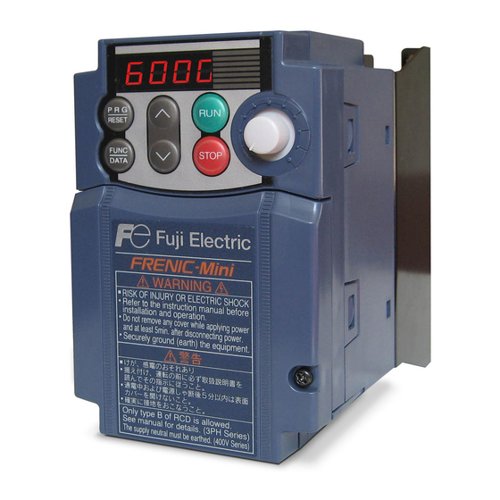
Fuji Electric Frenic-Mini User Manual
Compact inverter
Hide thumbs
Also See for Frenic-Mini:
- User manual (366 pages) ,
- Instruction manual (196 pages) ,
- Supplement to instruction manual (6 pages)
Table of Contents
Advertisement
Quick Links
Advertisement
Table of Contents

Summary of Contents for Fuji Electric Frenic-Mini
- Page 1 Compact Inverter User's Manual...
- Page 2 Copyright © 2002-2005 Fuji Electric FA Components & Systems Co., Ltd. All rights reserved. No part of this publication may be reproduced or copied without prior written permission from Fuji Electric FA Components & Systems Co., Ltd. All products and company names mentioned in this manual are trademarks or registered trademarks of their respective holders.
- Page 3 Incorrect handling of the inverter may prevent the inverter and/or related equipment from operating correctly, shorten their lives, or cause problems. Listed below are the other materials related to the use of the FRENIC-Mini. Read them in conjunction with this manual as necessary.
-
Page 4: Safety Precautions
This product is not designed for use in appliances and machinery on which lives depend. Consult your Fuji Electric representative before considering the FRENIC-Mini series of inverters for equipment and machinery related to nuclear power control, aerospace uses, medical uses or transportation. When the... -
Page 5: Precautions For Use
Precautions for Use When driving a 400V general-purpose motor with an inverter using Driving a 400V extremely long wires, damage to the insulation of the motor may occur. Use general-purpose an output circuit filter (OFL) if necessary after checking with the motor motor manufacturer. - Page 6 Avoid such operation. Synchronous It is necessary to take special measures suitable for this motor type. Contact In running motors your Fuji Electric representative for details. special motors Single-phase motors are not suitable for inverter-driven variable speed operation. Use three-phase motors.
- Page 7 * Connect a DC reactor to the inverter. When checking the insulation resistance of the inverter, use a 500 V megger Megger test and follow the instructions contained in the FRENIC-Mini Instruction Manual (INR-SI47-0791-E), Chapter 7, Section 7.4 "Insulation Test." Control circuit...
- Page 8 Part 2 Driving the Motor Chapter 4 BLOCK DIAGRAMS FOR CONTROL LOGIC This chapter describes the main block diagrams for the control logic of the FRENIC-Mini series of inverters. Chapter 5 RUNNING THROUGH RS485 COMMUNICATION (OPTION) This chapter describes an overview of inverter operation through the RS485 communications facility. Refer to the RS485 Communication User's Manual (MEH448) for details.
- Page 9 Chapter 9 FUNCTION CODES This chapter contains overview lists of seven groups of function codes available for the FRENIC-Mini series of inverters and details of each function code.
- Page 10 CONTENTS Part 1 General Information Chapter 1 INTRODUCTION TO FRENIC-Mini Features..............................1-1 Control System ............................1-8 Recommended Configuration ........................1-9 Chapter 2 PARTS NAMES AND FUNCTIONS External View and Allocation of Terminal Blocks..................2-1 LED Monitor, Potentiometer and Keys on the Keypad ................2-2 Chapter 3 OPERATION USING THE KEYPAD Overview of Operation Modes........................
- Page 11 5.1.2 Connector specifications ........................5-3 5.1.3 Connection ............................5-3 Part 3 Peripheral Equipment and Options Chapter 6 SELECTING PERIPHERAL EQUIPMENT Configuring the FRENIC-Mini......................... 6-1 Selecting Wires and Crimp Terminals....................... 6-2 6.2.1 Recommended wires ........................... 6-4 6.2.2 Crimp terminals........................... 6-6 Peripheral Equipment ..........................6-7 Selecting Options............................
- Page 12 Part 5 Specifications Chapter 8 SPECIFICATIONS Standard Models ............................8-1 8.1.1 Three-phase 200 V series ........................8-1 8.1.2 Three-phase 400 V series ........................8-2 8.1.3 Single-phase 200 V series ........................8-3 Models Available on Order ........................8-4 8.2.1 EMC filter built-in type........................8-4 8.2.1.1 Three-phase 200 V series ......................
- Page 13 Appendices App.A Advantageous Use of Inverters (Notes on electrical noise) ..............A-1 Effect of inverters on other devices....................A-1 Noise ..............................A-2 Noise prevention ..........................A-4 App.B Japanese Guideline for Suppressing Harmonics by Customers Receiving High Voltage or Special High Voltage ........................... A-12 Application to general-purpose inverters ..................


Need help?
Do you have a question about the Frenic-Mini and is the answer not in the manual?
Questions and answers