
Related Manuals for Grizzly G5394


Summary of Contents for Grizzly G5394
- Page 1 MODEL G5394 STROKE SANDER OWNER'S MANUAL WARNING: NO PORTION OF THIS MANUAL MAY BE REPRODUCED IN ANY SHAPE OR FORM WITHOUT THE WRITTEN APPROVAL OF GRIZZLY INDUSTRIAL, INC.
-
Page 3: Table Of Contents
INTRODUCTION ... 2 SECTION 1: SAFETY ... 6 SECTION 2: CIRCUIT REQUIREMENTS ... 9 SECTION 3: SETUP ... 10 SECTION 4: OPERATIONS ... 21 Table of Contents SECTION 5: ACCESSORIES ... 26 SECTION 6: MAINTENANCE ... 28 SECTION 7: SERVICE ... 30 SECTION 8: WIRING ... -
Page 4: Introduction
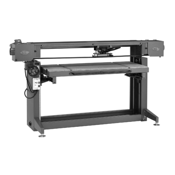
INTRODUCTION Manual Accuracy Functional Overview your machine may not exactly match the manual www.grizzly.com Contact Info... - Page 5 Identification Figure 1.
-
Page 6: Machine Data Sheet
Machine Data Sheet Customer Service #: (570) 546-9663 · To Order Call: (800) 523-4777 · Fax #: (800) 438-5901 MODEL G5394 STROKE SANDER Weight... 608 lbs. Length/Width/Height... 93-3/4 x 38 x 50 in. Foot Print (Length/Width)... 70 x 30-1/2 in. - Page 7 Sanding Belt Width...6 in. Sanding Belt Length... 186 in. Sanding Belt Speed...3500 FPM Drive Roller Type... Aluminum Drive Roller Length... 6-3/4 in. Drive Wheel Diameter... 8 in. Idler Roller Type...Aluminum Idler Roller Length...6-3/4 in. Idler Roller Diameter... 8 in. Platen Type... Graphite/Steel Platen Length...
-
Page 8: Safety Instructions For Machinery
Safety Instructions for Machinery... - Page 10 Additional Safety for Stroke Sanders RESPIRATOR AND SAFETY GLASSES. DUST COLLECTION SYSTEM HAND PROTECTION SANDING CORRECT MATERIAL. Like all machinery there is potential danger when operating this machine. Accidents are fre- quently caused by lack of familiarity or failure to pay attention. Use this machine with respect and caution to decrease the risk of operator injury.
-
Page 11: Section 2: Circuit Requirements
SECTION 2: CIRCUIT REQUIREMENTS 220V Operation Serious personal injury could occur if you connect the machine to power before com- pleting the setup process. DO NOT connect the machine to the power until instructed later in this manual. Electrocution or fire could result if machine is not grounded and installed in compliance with electrical... -
Page 12: Section 3: Setup
SECTION 3: SETUP Setup Safety This machine presents serious injury hazards to untrained users. Read through this entire manu- al to become familiar with the controls and opera- tions before starting the machine! Wear safety glasses dur- ing the entire setup pro- cess! This machine and its com- ponents are very heavy. - Page 13 Inventory Note: If you can't find an item on this list, check the mounting location on the machine or examine the packaging materials carefully. Occasionally we pre-install certain components for shipping purposes. SUFFOCATION HAZARD! Immediately discard all plas- tic bags and packing materi- als to eliminate choking/suf- focation hazards for children and animals.
- Page 14 Table Components: (Figure 6) Figure 6. Additional Components: (Figure 7) Figure 7. Hardware/Tools: (Figure 8) Figure 8. Note: Extra fasteners are included with the machine. You may be left with extra hardware after assembly is complete.
-
Page 15: Hardware Recognition Chart
Hardware Recognition Chart... -
Page 16: Site Considerations
Clean Up Figure 9 For optimum performance, clean all moving parts or sliding contact surfaces. Gasoline and petroleum products have low flash points and can explode or cause fire if used to clean machinery. NOT use these products to clean the machinery. Many cleaning solvents toxic Minimize your risk by only... - Page 17 Assembly To assemble your machine: Figure 11 Figure 11. Foot assembly attachment. Step 1 Figure 12 Figure 12. Second upright assembly. Figure 13 Figure 13. Third cross brace.
- Page 18 Figure 14. Top rail attachment. Figure 15. Figure 15. Motor bolt. Figure 14 Figure 16. Platen assembly. Figure 17. Table elevation rod. Note: To make sure both sides are set evenly, fully lower both before connecting the table elevation rod. Figure 16...
- Page 19 Figure 18 Figure 18. Inserting table rods. Figure 19 Figure 19. Attaching table. Figure 20 Figure 20. Idler wheel assembly. Figure 21 Figure 21. Belt tracking.
- Page 20 Figure 22 Figure 22. Idler wheel cover. Figure 23 Figure 23. Knob placement. Steps 15 16 Figure 24 Figure 24. Gearbox shaft. Figure 25 Figure 25. Handwheel placement.
-
Page 21: Machine Leveling
Figure 26 Figure 26. Switch box mounting. Figure 27. Replacing cover. Figure 28. Attaching handle. Machine Leveling Figure Figure 29. Machine leveling. Figure Figure... -
Page 22: Dust Collection
Dust Collection DO NOT operate the Model G5394 without an adequate dust collection system. This sand- er creates substantial amounts of wood dust while operating. Failure to use a dust collec- tion system can result in short and long-term respiratory illness. -
Page 23: Section 4: Operations
OMMEND that you read books, trade maga- zines, or get formal training before begin- ning any projects. Regardless of the con- tent in this section, Grizzly Industrial will not be held liable for accidents caused by lack of training. Basic Controls Figures 31–32... -
Page 24: Table Movement
Belt Tension Handwheel: Platen Press Handle: Table Movement Handle: Figure 32. Basic controls (continued). Table Movement To move the table vertically: Figure 33 Figure 33. Vertical table movement. Note: Due to the locking nature of the worm- drive gearbox, no lock is needed to prevent vertical table movement. - Page 25 Workstops The belt speed on the Model G5394 is 3500 FPM, or nearly 40 MPH. A workpiece ejected at this speed could cause serious personal injury and property damage. Always use the workstops and be sure they are in the cor- rect position and secured before using the machine.
-
Page 26: Sanding Belt Replacement
Sanding Belt Replacement To replace the sanding belt: Figure 36 Figure 36. Belt covers open. Figure 37 Figure 37. Installing new belt. Belt Tracking Page 32. -
Page 27: Platen Press Movement
Platen Press Movement Figures 38 Figure 38. Sanding movements. To move the platen press: To move the table: Basic Operations To perform sanding operations: Note: The proper amount of pressure to apply is dependent on a number of factors, including the grit of sandpaper being used, the type and moisture content of the wood being used, and the condition of the sand- paper. -
Page 28: Section 5: Accessories
SECTION 5: ACCESSORIES T20501—Face Shield Crown Protector 4" T20502—Face Shield Crown Protector 7" T20503—Face Shield Window T20448—Economy Clear Safety Glasses T20452—"Kirova" Anti-Reflective Glasses T20456—"Dakura" Clear Safety Glasses H0736—Shop Fox ® Safety Glasses T20502 T20503 T20456 Figure 39. G5443—6" x 186"; 60 Grit G5444—6"... - Page 29 T20514—Small Half-Mask Respirator T20515—Medium Half-Mask Respirator T20516—Large Half-Mask Respirator T20511—Pre-Filter P100 T20539—Cartridge Filter 2PK P100 T20541—Cartridge Filter 2PK P100 & O Vapor Figure 42. H2443—Universal Adapter Figure 43. G2752—4" Rolling Floor Sweep G2753—4" Bench Dust Collection Attachment G2754—4" Floor Dust Collection Attachment Figure 44.
-
Page 30: Section 6: Maintenance
SECTION 6: MAINTENANCE Always disconnect power to the machine before performing maintenance. Failure to do this may result in serious person- al injury. Schedule Daily Check: Weekly Maintenance: Every 500 Hours: Cleaning Accessories Page 26 Lubrication Table Elevation Ways Figure 45 Figure 45. - Page 31 Table Elevation Chain Table Elevation Gearbox Figure 47 Figure 46 Figure 47. Table elevation gearbox. Figure 46. Table elevation chain.
-
Page 32: Section 7: Service
SECTION 7: SERVICE Troubleshooting Motor & Electrical Page 35 Page 35... - Page 33 Operations Machine vibrates exces- sively (non-motor relat- ed). Page 24 Page 24 Deep sanding grooves or scores in workpiece. Abrasive grit rubs off the belt easily. Sanding belt surface clogs quickly or burns. Burn marks workpiece. Glazed sanding surfaces. Belt rubs on machine Page 32 frame.
-
Page 34: Table Bearings
Table Bearings Tools Needed To adjust the bearing assemblies: Figure 48 Figure 48. Table bearing adjustment (table removed for clarity). Steps 1–3 Belt Tracking Tools Needed To adjust the sanding belt tracking: Figure 49. Belt tracking adjustment. Steps 4–5 Figure 49... - Page 35 Table Elevation Wear Pin Adjustment Tools Needed To adjust the wear pins: Figure 50. Wear pin adjustment. Figure 50 Steps 2–4...
-
Page 36: Section 8: Wiring
SHOCK HAZARD. QUALIFIED ELECTRICIAN. WIRE CONNECTIONS. MOTOR WIRING. The photos and diagrams included in this section are best viewed in color. You can view these pages in color at www.grizzly.com. WIRE/COMPONENT DAMAGE. MODIFICATIONS. CAPACITORS. CIRCUIT REQUIREMENTS. Page 9 EXPERIENCING DIFFICULTIES. -
Page 37: Wiring Diagram
Wiring Diagram View this page in color at www.grizzly.com. 220 VAC 6-20 PLUG (as recommended) 220V MOTOR Figure 51. Switch wiring. WARNING! SHOCK HAZARD! Disconnect power before working on wiring. Figure 52. Motor wiring. READ ELECTRICAL SAFETY ON PAGE 34! -
Page 38: Section 9: Parts
SECTION 9: PARTS Main Breakdown... -
Page 39: Main Parts List
SET SCREW 5/16-18 X 3/8 HANDLE SET SCREW 5/16-18 X 3/8 FOLLOWING WHEEL AXLE ADJUSTING SCREW 1/2-12 X 2 SANDER BELT 6" X 186" LOCK WASHER 5/16 FLAT WASHER 4MM CAP SCREW M6-1 X 20 (LH) SET SCREW 1/4-20 X 1/2... - Page 40 Table Assembly Breakdown...
- Page 41 Table Assembly Parts List REF PART # DESCRIPTION P5394201 TABLE BRACKET RIGHT 201-1 P5394201-1 TABLE BRACKET LEFT P5394202 COPPER BAR 5/16" X 10MM PN08 HEX NUT 3/8"-16 PB18 HEX BOLT 3/8-16 X 1 P5394205 PLATE P5394206 KEY WHEEL FIXING PLATE P5394207 SET SCREW 8-32 X 1 P5394208...
- Page 42 Platen Press Breakdown...
- Page 43 Platen Press Parts List REF PART # DESCRIPTION PR11M EXT RETAINING RING 25MM PW19M FLAT WASHER 25MM P5394303 MIDDLE POST SPRING 3.2 X 35 X 82 P5394304 MIDDLE POST PB51 HEX BOLT 1/4-20 X 3/8 PW06 FLAT WASHER 1/4 P6001 BALL BEARING 6001ZZ P5394308 BACK BEARING PILLAR...
-
Page 44: Labels Breakdown & Parts List
MUST maintain the original location and readability of the labels on the machine. If any label is removed or becomes unreadable, REPLACE that label before using the machine again. Contact Grizzly at (800) 523-4777 or www.grizzly.com to order new labels. REF PART #... -
Page 47: Warranty And Returns
WARRANTY AND RETURNS...
Need help?
Do you have a question about the G5394 and is the answer not in the manual?
Questions and answers