Table of Contents
Advertisement
Quick Links
Download this manual
See also:
Instruction Manual
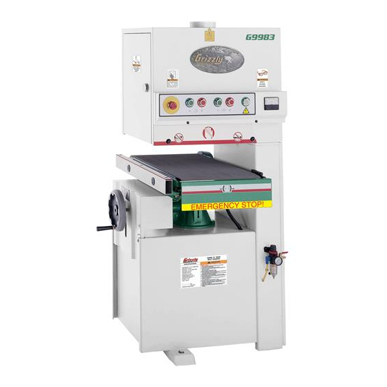
model g9983
15" open-end
Wide-belt sander
oWner's manual
(For models manufactured since 8/09)
Copyright © oCtober, 2002 by grizzly industrial, inC., revised June, 2013 (ts)
Warning: no portion of this manual may be reproduced in any shape
or form Without the Written approval of grizzly industrial, inc.
#tr4202 printed in taiWan
Advertisement
Table of Contents

Related Manuals for Grizzly g9983


Summary of Contents for Grizzly g9983
- Page 1 (For models manufactured since 8/09) Copyright © oCtober, 2002 by grizzly industrial, inC., revised June, 2013 (ts) Warning: no portion of this manual may be reproduced in any shape or form Without the Written approval of grizzly industrial, inc.
- Page 2 This manual provides critical safety instructions on the proper setup, operation, maintenance, and service of this machine/tool. Save this document, refer to it often, and use it to instruct other operators. Failure to read, understand and follow the instructions in this manual may result in fire or serious personal injury—including amputation, electrocution, or death.
-
Page 3: Table Of Contents
table of contents introduction ..........2 section 4: operations ......22 Contact info............ 2 operation overview ........22 Manual accuracy ........... 2 Choosing sandpaper ........23 Machine data sheet ........3 Conveyor belt height ........23 basic Controls & Features ......5 Feed belt speed .......... -
Page 4: Introduction
This will help us help you faster. tions, specifications, drawings, and photographs contained inside. sometimes we make mistakes, Grizzly Technical Support but our policy of continuous improvement also 1203 Lycoming Mall Circle means that sometimes the machine you receive... -
Page 5: Machine Data Sheet
machine data sheet MACHINE DATA SHEET Customer Service #: (570) 546-9663 · To Order Call: (800) 523-4777 · Fax #: (800) 438-5901 MODEL G9983 15" WIDE-BELT SANDER (OPEN END) Product Dimensions: Weight................................815 lbs. Width (side-to-side) x Depth (front-to-back) x Height............... 32-1/2 x 35 x 61-3/4 in. Footprint (Length x Width)........................ - Page 6 Main Specifications: Operation Information No Of Sanding Heads............................1 Maximum Board Width..........................15 in. Minimum Board Width..........................2 in. Maximum Board Thickness........................5-1/2 in. Minimum Board Thickness........................1/8 in. Minimum Board Length..........................12 in. Sandpaper Speed..........................2050 FPM Sanding Belt Oscillations......................... 5/8 – 3/4 in. Conveyor Feed Rate........................
-
Page 7: Basic Controls & Features
basic controls & control panel the control panel houses the main power switch, features the feed belt on/oFF buttons and the sanding belt on/oFF buttons. please refer to figure 2 to identify these controls. to help you understand the set up and operation a. -
Page 8: Left Access Door
left access door right access door figure 4 shows the layout behind the right-hand there are access doors located on each side of the sander. throughout the manual, we refer to access door. these doors as the “left-hand access door” and a. -
Page 9: Section 1: Safety
section 1: safety for your own safety, read instruction manual before operating this machine the purpose of safety symbols is to attract your attention to possible hazardous conditions. this manual uses a series of symbols and signal words intended to convey the level of impor- tance of the safety messages. - Page 10 Wearing proper apparel. do not wear forcing machinery. do not force machine. clothing, apparel or jewelry that can become it will do the job safer and better at the rate for entangled in moving parts. always tie back or which it was designed. cover long hair.
-
Page 11: Additional Safety For Wide-Belt Sanders
additional safety for Wide-belt sanders KicKbacK. Kickback is typically defined as the WorKpiece Quantity. never sand two or high-speed expulsion of stock from the machine, more workpieces side-by-side. since workpieces which can cause serious personal injury to the are never exactly the same thickness, one of them operator or bystanders. -
Page 12: Section 2: Power Supply
section 2: poWer supply availability circuit information Before installing the machine, consider the avail- A power supply circuit includes all electrical ability and proximity of the required power supply equipment between the breaker box or fuse panel circuit. If an existing circuit does not meet the in the building and the machine. -
Page 13: Connection Type
connection type grounding instructions A permanently connected (hardwired) power sup- In the event of a malfunction or breakdown, ply is typically installed with wires running through grounding provides a path of least resistance mounted and secured conduit. A disconnecting for electrical current to reduce the risk of electric means, such as a locking switch (see following shock. -
Page 14: Section 3: Setup
section 3: setup unpacking inventory Your machine was carefully packaged for safe The following is a list of items shipped with your transportation. Remove the packaging materials machine. Before beginning setup, lay these items from around your machine and inspect it. If you out and inventory them. -
Page 15: Cleanup
cleanup Gasoline or products with low flash points can The unpainted surfaces of your machine are explode or cause fire if coated with a heavy-duty rust preventative that used to clean machin- prevents corrosion during shipment and storage. ery. Avoid cleaning with This rust preventative works extremely well, but it these products. -
Page 16: Site Considerations
site considerations Weight Load Physical Environment Refer to the Machine Data Sheet for the weight The physical environment where the machine is of your machine. Make sure that the surface upon operated is important for safe operation and lon- which the machine is placed will bear the weight gevity of machine components. -
Page 17: Mounting
mounting NOTICE anchor studs are the strongest option, but they stick out of the floor—permanently. although not required, we recommend that you before using, make sure you have enough mount your new machine to the floor. because clearance to lift the machine over the studs this is an optional step and floor materials may if it must be moved in the future. -
Page 18: Assembly
assembly installing platen the housing for the platen can be accessed by opening the door on the left-hand side of the machine. a graphite sheet is mounted on the platen. before Serious injury could occur if you connect installing, make sure that the graphite sheet is the machine to power before completing the mounted on the left-hand side of the platen, as it setup process. -
Page 19: Connecting Air Hose
connecting air hose the platen must now be set even with the sanding rollers. the air hose connection is located at the regulator on the front of the machine. to set the platen even with the belt rollers: to connect the air hose: lower the conveyor table as far as it will go. -
Page 20: Installing Sanding Belt
installing sanding belt sanding belt tension the Model g9983 is designed for 16" x 48" sand- the sanding belt tension is controlled by a switch ing belts. located inside the upper portion of the machine (see figure 14). to locate it, open the access to install a sanding belt: door on the left-hand side of the sander. -
Page 21: Pressure Rollers
5" hose clamp and it absorbs any movement then the pressure rollers must be adjusted that may occur during operation. please refer to before operation. see section 8: service the grizzly catalog for current price and ordering adjustments for step-by-step instructions information. on how to do this. -
Page 22: Power Connection
power connection test run Before the machine can be connected to the once the assembly is complete, test run your power source, an electrical circuit and connec- machine to make sure it runs properly. tion device must be prepared per the POWER SUPPLY section in this manual;... -
Page 23: Recommend Adjustments
recommend recommended adjustment checklist: adjustments • pressure rollers • oscillation timing For your convenience, the adjustments listed • oscillation speed below have been performed at the factory and no further setup is required to operate your • oscillation return machine. •... -
Page 24: Section 4: Operations
-22- Model G9983 (Mfg. Since 8/09) -
Page 25: Choosing Sandpaper
choosing sandpaper conveyor belt height the Model g9983 takes 16"W x 48"l sanding Conveyor height is controlled by turning the hand- wheel shown in figure 17. a scale is located near belts. the handwheel for gauging conveyor movement. the grit you choose will depend on the type of the scale is marked in millimeters and inches. -
Page 26: Feed Belt Speed
feed belt speed load meter the feed belt motor (shown in figure 19 with the the load meter shown in figure 20 displays the cover removed) controls the speed of the feed current amperage draw of the sanding belt motor. belt. -
Page 27: Platen Depth
platen depth the three basic platen positions: platen up: the platen is raised above the level of the sanding rollers. this position allows the front the platen position allows for 3 types of opera- roller to remove large amounts of material quickly, tion. -
Page 28: Section 5: Accessories
26 ⁄ " to 44 ⁄ ". recommended for this machine by grizzly. NOTICE refer to our website or latest catalog for additional recommended accessories. h2845—pro-sticK sanding pad ®... -
Page 29: Section 6: Maintenance
(see the previous page for an option from grizzly). figure 25. unscrew this filter to empty it. -27-... -
Page 30: Section 7: Service
section 7: service Review the troubleshooting and procedures in this section if a problem develops with your machine. If you need replacement parts or additional help with a procedure, call our Technical Support at (570) 546-9663. Note: Please gather the serial number and manufacture date of your machine before calling. troubleshooting symptom possible cause... - Page 31 symptom possible cause possible solution lines across width 1. sanding belt seam is open or damaged. 1. repair or replace sanding belt. of workpiece. More material is 1. Workpiece is not supported as it comes out 1. hold workpiece up with your hands as it comes out, removed from the of sander.
-
Page 32: Oscillation Timing
oscillation timing loosen the belt tension, rebalance the sand- ing belt and retighten the belt tension. repeat steps 2–3. the first step in adjusting the oscillation is timing When you get the belt to oscillate without the side to side movement the belt makes when stopping, experiment with the timing knob to oscillating. -
Page 33: Oscillation Return
to increase the oscillation speed, open the valve to adjust the oscillation return: (turn the knob counter-clockwise). For normal operation, adjust the oscillation speed so each disconnect the sander from power, but keep direction of belt movement takes approximately 2 air pressure going into the machine. -
Page 34: Limit Switches
limit switches pressure roller depth the limit switches are mounted on both sides of the sanding belt. they are designed to stop the variables such as feed rate, depth of the cut, and sander if the belt travels too far to one side of the type of sanding belt can play a big part in deter- top roller. -
Page 35: Pressure Roller Tension
pressure roller With the air pressure connected, and the sanding belt installed and tensioned, raise tension the pressure rollers above the sanding belt rollers. adjust the platen to be even with the bottom pressure roller tension is largely set by trial and of the front sanding belt roller. -
Page 36: Feed Belt Tension
feed belt tension feed belt tracking to adjust the feed belt tension: to check the feed belt tracking: turn the feed belt ON. disConneCt sander FroM poWer! Move the emergency brake plate up and out if the belt moves to one side then you need to of the way. -
Page 37: V-Belt Tension
v-belt tension replacing v-belts the sanding belt is driven by two v-belts on the inspect the v-belts closely; if you see any glaz- Model g9983. the v-belts must have adequate ing, cracking or fraying, replace the belts. always tension for proper power transmission. proper replace the two v-belts at the same time for tension is usually achieved when the v-belts can proper power transmission. - Page 38 to remove the v-belts from the roller pulley, open the right-hand access door and locate the roller needs to be removed. open the the large nut shown in figure 37 and remove left-hand access door and remove the platen it with the box wrench included with the micro-adjust knob by loosening the setscrew machine.
-
Page 39: Platen Graphite
platen graphite air system the graphite sheet on the platen will wear out the air system is durable and reliable; however, with use. similar to the sanding belts, the graphite components do wear with age. if you suspect that sheet is considered a “consumable” item and is an item in your air system may be having prob- lems, use the diagram on page 39 to follow all not covered under the warranty. -
Page 40: Replacing Brakes
replacing brakes the only regular maintenance to perform on the brakes is to keep the rotor clean. this is a simple process and can be performed by spraying both sides of the rotor with automotive brake parts cleaner. the brake rotor must be free and clean of any dust, dirt, oil or moisture. -
Page 41: Air System
air system various functions on the Model g9983 are con- the valve (g) controls the air flow volume trolled through the air system. since this is a that goes to the air eye fork (F), which con- complex network of hoses and valves, please trols the belt oscillation return. -
Page 42: Section 8: Wiring
Technical source. Support at (570) 546-9663. The photos and diagrams included in this section are best viewed in color. You can view these pages in color at www.grizzly.com. -40- Model G9983 (Mfg. Since 8/09) -
Page 43: Electrical Panel Wiring Diagram
Model g9983 electrical panel Wiring diagram Wiring diagram—Main hook up panel 220 volt single-phase TO BRAKING TO BELT & TO FEED to belt & raKing to Feed STOP SWITCHES SOLENOID VALVE MOTOR oid valve stop sWitChes Motor 12 13 U2 V2 12 13 u2 v2 220V POWER... -
Page 44: Control Panel Wiring
READ ELECTRICAL SAFETY -42- Model G9983 (Mfg. Since 8/09) ON PAGE 40! -
Page 45: Motor & Limit Switch Wiring
Model g9983 Wiring diagram - 220 volt single phase Main Motor starting 250vaC Capacitor 800MFd running 350vaC Capacitor 50uF-u belt liMit sWitCh Feed belt Motor eMergenCy stop liMit sWitCh solenoid valve 12 13 u2 v2 W2 u1 v1 W1 disconnect power from machine before performing any electrical service. -
Page 46: Section 9: Parts
section 9: parts accessories REF PART # DESCRIPTION REF PART # DESCRIPTION P9983001 TOOL BOX PWR1719 WRENCH 17 X 19MM OPEN-END PWR1214 WRENCH 12 X 14MM OPEN-END PWR1113 WRENCH 11 X 13MM OPEN-END P9983003 FLAT WRENCH 30/37MM PWR810 WRENCH 8 X 10MM OPEN-END PSDP2 PHLP HD SCREWDRIVER #2 PAW1510M... - Page 47 base & sanding motor 155-1 155-5 155-3 155-2 155-4 155-7 155-6 155-9 155-8 102-1 113-1 -45- Model G9983 (Mfg. Since 8/09)
- Page 48 base & sanding motor parts list REF PART # DESCRIPTION REF PART # DESCRIPTION P9983101 MACHINE BASE P9983135 MOTOR MOUNT L-BOLT P9983102-1 QUILL BASE PW06M FLAT WASHER 12MM 102-1 P9983102-1 QUILL ASSY PN09M HEX NUT M12-1.75 PCAP64M CAP SCREW M10-1.5 X 25 P9983138 BRAKE PIN PLW06M...
- Page 49 conveyor 243-4 243-1 243-3 243-2 243-5 251 238 243-7 243-8 243-6 219 220 REF PART # DESCRIPTION REF PART # DESCRIPTION P9983201 CONVEYOR SUPPORT PK67M KEY 8 X 7 X 15 P9983202 ROLLER BRACKET LH P9983232 MOTOR PANEL P9983203 ROLLER BRACKET RH P6205ZZ BALL BEARING 6205ZZ PLW04M...
- Page 50 sanding belt drive system 381-1 345A -48- Model G9983 (Mfg. Since 8/09)
- Page 51 sanding belt drive system parts list REF PART # DESCRIPTION REF PART # DESCRIPTION P9983301 CONTACT ROLLER BASE PR11M EXT RETAINING RING 25MM PLW06M LOCK WASHER 10MM PR25M INT RETAINING RING 47MM PCAP72M CAP SCREW M10-1.5 X 30 P6005ZZ BALL BEARING 6005ZZ P9983304 SWITCH PLATE 345A P9983345A CONTACT ROLLER ASSEMBLY PW04M...
- Page 52 sanding cabinet & air system 441-1 522V2 522V2 501-1 533-1 -50- Model G9983 (Mfg. Since 8/09)
- Page 53 sanding cabinet & air system parts list REF PART # DESCRIPTION PART # DESCRIPTION P9983401 MACHINE FRAME P9983444 CUP 1/4" P9983402 ACCESS DOOR RH P9983518 PLASTIC CONNECTOR C6-1/8" P9983403 ACCESS DOOR LH P9983501 SWITCHING VALVE P9983404 DOOR LOCK ASSEMBLY 501-1 P9983501-1 SWITCHING VALVE SWITCH P9983405 OPERATING PANEL...
- Page 54 electrical cabinet 605V2 606V2 606-1V2 604V2 725* 724* 728* 723* 729* 730* 713 714 720* 718* 721* 719* 722* 726* * Optional Parts -52- Model G9983 (Mfg. Since 8/09)
- Page 55 PART # DESCRIPTION REF PART # DESCRIPTION P9983601 CONTROL BOX P9983705 TABLE SUPPORT W/SUPPORT LINING P9983602 DOOR LOCK ASSEMBLY PS11M PHLP HD SCR M6-1 X 16 P9983603 ELECTRICAL MOUNTING PLATE PW03M FLAT WASHER 6MM 604V2 P9983604V2 CONTACTOR CN-27 SAND 220V TECO V2.10.08 PN01M HEX NUT M6-1 605V2...
- Page 56 Safety labels help reduce the risk of serious injury caused by machine hazards. If any label comes off or becomes unreadable, the owner of this machine MUST replace it in the original location before resuming operations. For replacements, contact (800) 523-4777 or www.grizzly.com. -54-...
- Page 57 Would you recommend Grizzly Industrial to a friend? _____ Yes _____No Would you allow us to use your name as a reference for Grizzly customers in your area? Note: We never use names more than 3 times. _____ Yes _____No 10.
- Page 58 FOLD ALONG DOTTED LINE Place Stamp Here GRIZZLY INDUSTRIAL, INC. P.O. BOX 2069 BELLINGHAM, WA 98227-2069 FOLD ALONG DOTTED LINE Send a Grizzly Catalog to a friend: Name_______________________________ Street_______________________________ City______________State______Zip______ TAPE ALONG EDGES--PLEASE DO NOT STAPLE...
-
Page 59: Warranty & Returns
Warranty & returns Grizzly Industrial, Inc. warrants every product it sells for a period of 1 year to the original purchaser from the date of purchase. This warranty does not apply to defects due directly or indirectly to misuse, abuse, negligence, accidents, repairs or alterations or lack of maintenance.
Need help?
Do you have a question about the g9983 and is the answer not in the manual?
Questions and answers