
Subscribe to Our Youtube Channel
Related Manuals for Eaton MX 4000 RT


Summary of Contents for Eaton MX 4000 RT
- Page 1 4000 RT 5000 RT Installation and user manual English Français Deutsch Italiano Español Nederlands Pulsar Series...
-
Page 2: Environmental Protection
Before installing MX, please read the booklet on the required safety instructions. Then follow the indications in this manual. To discover the entire range of EATON products and the options available for the MX range, we invite you to visit our web site at www.eaton.com or contact your EATON representative. -
Page 3: Table Of Contents
Contents Troubleshooting Troubleshooting LEDS (21) and (22) ..................28 Troubleshooting not requiring EATON after-sales support .............28 Troubleshooting requiring EATON after-sales support............29 Life Cycle Monitoring (LCM) Description ..........................30 Secure your installation power continuity..................30 Reset or disable LCM ........................30 Maintenance Hot swapping the power sub-module..................31 Hot swapping the battery sub-module ..................31... -
Page 4: Standard Positions
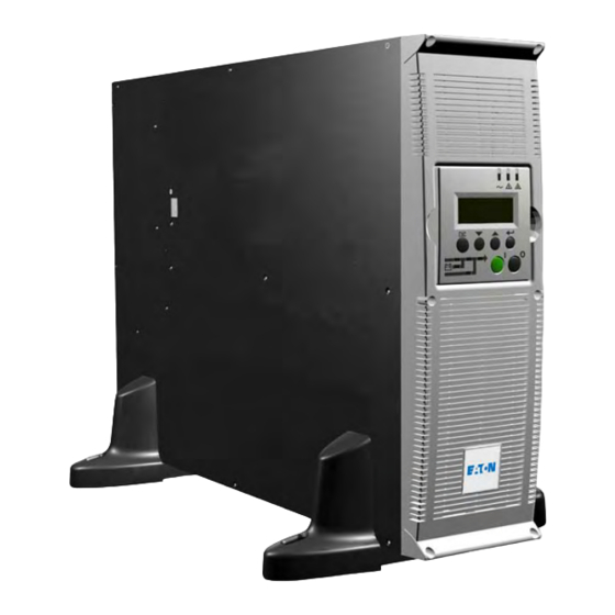
1. Presentation 1.1 Standard positions Tower position Dimensions (H x W x D) in mm / Inches MX 4000 RT 444.5 x 131 x 700 / 17.5 x 5.16 x 27.56 MX 5000 RT 444.5 x 131 x 700 / 17.5 x 5.16 x 27.56... -
Page 5: Rear Panels
1. Presentation 1.2 Rear panels MX 4000 RT / 5000 RT (1) Two groups of 2 programmable (10A) outlets for connection of equipment (2) Groups of 4 (10A) outlets for connection of equipment (3) Groups of 2 (16A) outlets for... -
Page 6: Display And Control Panel
1. Presentation 1.3 Display and control panel (20) Load protected LED (21) Downgraded operation LED (22) Load not protected LED (23) Alphanumeric display (24) Escape (cancel) button (25) (26) Function buttons (scroll down / scroll up) (27) Enter (confirm) button (28) UPS OFF button (29) UPS ON button (30) Rectifier LED... - Page 7 1. Presentation ModularEasy MX ModularEasy enables parallel operation when combining two MX UPSs. Consequently you can enhance the availbility level of your equipment (N+1 redundancy). You can also double your secured power capacity according to your needs (migration, network extension...). In the unlikely event a major fault would occur, the manual maintenance bypass of MX ModularEasy would allow the UPS...
- Page 8 1. Presentation Battery extensions for UPS backup times up to 80 minutes (at full load) MX RT offers a standard backup time of 5/7 minutes at full load. To increase backup time, it is possible to connect MX EXB RT modules to the UPSs. Battery extensions for MX RT Battery Integration System The Battery Integration System is...
-
Page 9: Unpacking And Contents Check
2. Installation 2.1 Unpacking and contents check (40) MX 4000 or 5000 UPS. (46) Screw driver. (41) Two sets of tower stands. (47) Solution-Pac power management suite CD-ROM. (42) RS232 communications cable (48) Network Management card (optional, or standard in NetPack version). -
Page 10: Installation In Tower Position
2. Installation 2.3 Installation in tower position Follow steps 1 to 3 to adjust the tower stands for the upright position. Always keep 150 mm free space behind the UPS rear panel. The distance between the tower stands should be 450 mm. 34008030EN/AD - Page 13... -
Page 11: Installation In Rack Position
2. Installation 2.4 Installation in rack position Adjustment of the orientation of the logo and control panel UPS module rack mounting (optional rails required) MX RT is very heavy. To ease its rack integration, we strongly recommend to remove the battery tray as shown below: 1 - Remove the 6 fixing screws to free the main front panel bezel. - Page 12 Follow steps 1 to 4 for rack mounting the UPS onto the rails. The rails and the necessary mounting hardware are supplied by EATON. Note for step 1: it is possible to adjust the position of both front mounting ears.
-
Page 13: Communication Ports
The output contact port is used for basic signaling or for protection of IT systems like IBM iSeries (formerly AS400) and more. The slot is compatible with any EATON communication card (check www.eaton.com web site for the complete list of compatible cards). - Page 14 2. Installation Remote Power Off communication port (16) (see page 8) Installation of a Remote Power Off function must be carried out in compliance with applicable regulations. In order to fully de-energize devices and MX RT with the RPO port, it is necessary: to use a two-position switch (Normally Open or Closed contact should be held more than 1 second to be taken into account).
-
Page 15: Recommended Upstream Protection
2. Installation 2.6 Required protective devices and cable cross-sections Recommended upstream protection The indicated protection ensures UPS power rating Upstream circuit breaker discrimination for each output circuit 4000 RT D curve - 32A downstream of the UPS. If these recommendations are not 5000 RT D curve - 32A followed, protection discrimination is not... - Page 16 2. Installation 2.7 Connection of input/output power cables on UPS terminals This type of connection must be carried out by qualified electrical personnel. Before carrying out any connection, check that the battery circuit breaker (19) (see page 8) and that the upstream protection device (Normal AC source) is open ("0").
-
Page 17: Connection Of Iec Cables To Output Receptacles
16 A outlet (3). To program shutdown of outlets (2) during operation on battery power and thus optimise the available backup time, the EATON communication software is required. 2 - Fit the connection securing system (44) that prevents the plugs from being pulled out accidentally. - Page 18 3. Operation 3.1 Initial start-up It is essential to contact our Customer Service to ensure that your system is commissionned in complete safety and to benefit from the manufacturer’s guarantee. 1 - Check that the battery switch (60) (see section 2.2, page 12) on top cover is connected.
-
Page 19: Operating Modes
3. Operation 3.3 Operating modes Normal mode This is the standard operating mode, set by default in the factory. Under normal condition (Normal AC source available): LED (20) is ON. LEDs (30), (32), (34) are green. The equipments are protected by the UPS. -
Page 20: Operation On Battery Power
3. Operation 3.4 Operation on battery power When the Normal AC source is not available, the load continues to be protected by the UPS. Power is supplied by the battery. Transfer to battery power LEDs (20), (21) are ON. LEDs (31), (32), (34) are green. The audio alarm beeps every 10 seconds. -
Page 21: Ups Shutdown
3. Operation 3.6 UPS shutdown 1 - Press the "0" button (28) more than 3s. The buzzer beeps once, and the load is no longer protected by the UPS. It is powered via the Normal AC source. If the UPS is set in frequency converter mode, the equipments will not be powered. -
Page 22: Display Organisation
4. Access to measurements and personalisation data 4.1 Display organisation Measurements UPS Set-up Maintenance 4.2 Access to measurements Press the scroll button (24) (see section 1.3, page 9) to access measurements for voltage, current, frequency, power output and battery capacity. 4.3 Access to UPS set-up and maintenance using the control panel (23) Press the scroll button (25) a number of times to point the UPS set-up or... - Page 23 4. Access to measurements and personalisation data 4.4 UPS set-up Local settings Function Factory setting Options English French, German, Italian, Portuguese, Spanish Language Date / Time Format International US (MM-DD-YYYY/HH:MM AM/PM) (DD-MM-YYYY/HH :MM) Date / Time Change GMT + 1 MM-DD-YYYY/HH :MM adjustable (Continental Europe) Audible Alarm...
-
Page 24: Personalisation Using External Software
User Batt Settings UPS reads number of From 0 to 40 Ah 5 Ah increment battery modules connected Protection against deep discharge. Deep Disch Protect If disable, EATON warranty will be void 4.5 Maintenance Function Sub-Function Option / Display Comments Model... -
Page 25: Troubleshooting
(25) to get access to further details. In case of "LCM WARNING", refer to LCM section (see section 6). 5.2 Troubleshooting not requiring EATON after-sales support Press the "Enter" button (27) to display the details below : Displayed details Signification... -
Page 26: Troubleshooting Requiring Eaton After-Sales Support
5. Troubleshooting 5.3 Troubleshooting requiring EATON after-sales support Note: In case of multiple fault, press the "Enter" button (27) and the scroll button (25) to get access to further details. Display Signification Correction POWER MODULE FAULT Internal power sub-module fault detected. -
Page 27: Life Cycle Monitoring (Lcm)
: LCM warning details Signification BATTERY CHECK RECOMMENDED Battery is approaching its reliability end of life. Risk to reduce CONTACT EATON AT dramatically backup time www.eaton.com Reset or disable LCM In case of any LCM messages displayed:... -
Page 28: Maintenance
7. Maintenance 7.1 Hot swapping the power sub-module This operation must be carried out by qualified electrical personnel only. This operation can be performed without interrupting the equipments. Disconnecting the power sub-module : 1 - Remove the 6 fixing screws to free the main front panel bezel. -
Page 29: Maintenance On A Ups Equipped With The Modulareasy Mx Module
Reconnecting the battery sub-module : Carry out the above instructions in reverse order. To ensure safety and high performance, use only batteries supplied by EATON. 7.3 Maintenance on a UPS equipped with the ModularEasy MX module Before any action on the manual bypass (61) located on the ModularEasy module front panel, always check that the inverter is stopped (press the "0"... -
Page 30: Training Centre
7. Maintenance 7.4 Training centre To fully master operation of your EATON product and carry out level 1 servicing, see our complete range of technical training courses, available in both French and English. For further information, please visit our website: www.eaton.com... -
Page 31: Appendices
8. Appendices 8.1 Technical specifications MX 4000 MX 5000 MX EXB Output power 4000 VA / 5000 VA 3600 W 4500 W Electrical supply network Rated input voltage Single phase 230 V Input voltage range 120 / 156 V to 280 V Frequency 50/60 Hz (autoselection) Power factor... -
Page 32: Glossary
Personalisation It is possible to modify certain UPS parameters set in the factory. Certain UPS functions can also be modified by the EATON power management products to better suit user needs. These outlets can be automatically shut down during operation on battery power...
Need help?
Do you have a question about the MX 4000 RT and is the answer not in the manual?
Questions and answers