Table of Contents
Advertisement
Quick Links
Advertisement
Table of Contents

Related Manuals for Panasonic PLC-XU75A


Summary of Contents for Panasonic PLC-XU75A
- Page 1 Multimedia Projector PLC-XU75A MODEL Owner's Manual...
-
Page 2: Features And Design
Features and Design This Multimedia Projector is designed with the most advanced technology for portability, durability, and ease of use. This projector utilizes built-in multimedia features, a palette of 16.77 million colors, and matrix liquid crystal display (LCD) technology. ◆ Compact Design ◆... -
Page 3: Table Of Contents
Table of Contents Features and Design....2 Computer Input ....25 Table of Contents ....3 Input Source Selection Computer System Selection To the Owner . -
Page 4: To The Owner
To the Owner Safety Precaution Before operating this projector, read this manual thoroughly and operate the projector properly. – WARNING: THIS APPARATUS MUST BE EARTHED. This projector provides many convenient features and – TO REDUCE THE RISK OF FIRE OR ELECTRIC SHOCK, DO NOT EXPOSE THIS functions. -
Page 5: Safety Instructions
Safety Instructions All the safety and operating instructions should be read Do not install the projector near the ventilation duct of before the product is operated. air-conditioning equipment. Read all of the instructions given here and retain them for later use. Unplug this projector from AC power This projector should be operated only from the type supply before cleaning. -
Page 6: Air Circulation
Safety Instructions Air Circulation Installing the Projector Openings in the cabinet are provided for ventilation in Proper Position and to ensure reliable operation of the product and to Install the projector properly. Improper Installation protect it from overheating, and these openings must may reduce the lamp life and cause a fire hazard. -
Page 7: Compliance
Do not make any changes or modifications to the equipment unless otherwise specified in the instructions. If such changes or modifications should be made, you could be required to stop operation of the equipment. Model Number : PLC-XU75A Trade Name : Sanyo... -
Page 8: Part Names And Functions
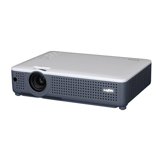
Part Names and Functions Front Infrared Remote Receiver Zoom Ring Projection Lens Focus Ring Lens Cover (See page 53 for attaching.) Air Intake Vent Power Cord Connector Back Speaker Terminals and Connectors Top Controls and Indicators Exhaust Vents CAUTION Hot air is exhausted from the exhaust vent. Do not put heat-sensitive objects near this side. -
Page 9: Rear Terminal
Part Names and Functions Rear Terminal SERVICE PORT AUDIO IN This jack is used to service the projector. Connect the audio output from video equipment connected to to this COMPUTER IN 1/COMPONENT IN jack. (When the audio output is monaural, connect it to L (MONO) jack.) (p.16) Connect output signal from a computer, R G B s c a r t 2 1- p i n v i d e o o u t p u t , o r... -
Page 10: Top Control
Part Names and Functions Top Control Top Control SELECT button LAMP REPLACE indicator – Execute the selected item. (p.20) Turn yellow when the life of the projection – Expand or compress the image in Digital lamp draws to an end. (p.55, 61) zoom mode. -
Page 11: Remote Control
Part Names and Functions Remote Control POWER ON/STAND-BY button Turn the projector on or off. (p.18, 19) VIDEO button Select VIDEO input source. (p.23, 35) COMPUTER button Select COMPUTER input source. (p.23, 25, 36) MENU button Open or close the On-Screen Menu. (p20) Point (VOLUME + / –) buttons ed 7 8... -
Page 12: Remote Control Battery Installation
Part Names and Functions Remote Control Battery Installation Open the battery Install new batteries Replace the compartment lid. into the compartment. compartment lid. Two AA size batteries For correct polarity (+ and –), be sure battery terminals are in contact with pins in the compartment. -
Page 13: Installation
Installation Positioning the Projector For projector positioning, see the figures below. The projector should be set horizontally to the flat screen. ✔ Note: • The brightness in the room has a great influence on picture quality. It is recommended to limit ambient lighting in order to obtain the best image. -
Page 14: Connecting The Ac Power Cord
Installation Connecting the AC Power Cord This projector uses nominal input voltages of 100-120 V or 200-240 V AC. This projector automatically selects the correct input voltage. It is designed to work with single-phase power systems having a grounded neutral conductor. -
Page 15: Connecting To A Computer
Installation Connecting to a Computer Cables used for connection • VGA Cables (Mini D-sub 15 pin) (Only one cable is supplied.) • Audio Cables (Mini Plug: stereo) (*One cable is supplied; other cables are not supplied with the projector.) Monitor Output External Audio Equipment Audio Output Monitor Output... -
Page 16: Connecting To Video Equipment
Installation Connecting to Video Equipment Cables used for connection • Video and Audio Cable (RCA x 3) • S-VIDEO Cable • Audio Cable (Mini Plug: stereo) ( Cables are not supplied with the projector.) S-Video Output Composite Video and Audio Output (R) (L) (Video) External Audio Equipment... -
Page 17: Connecting To Component Video Equipment
Installation Connecting to Component Video Equipment Cables used for connection • Audio Cables (Mini Plug :stereo) • Scart-VGA Cable • Component Cable • Component-VGA Cable ( Cables are not supplied with the projector.) Audio Output RGB Scart Component Video Output 21-pin Output (Y, Pb/Cb, Pr/Cr) Component cable... -
Page 18: Basic Operation
Basic Operation Turning On the Projector Complete peripheral connections (with a computer, VCR, etc.) before turning on the projector. Connect the projector’s AC power cord into an AC outlet. The POWER indicator becomes red. Press the POWER ON/STAND-BY button on the top control or on the remote control. -
Page 19: Turning Off The Projector
Basic Operation Turning Off the Projector Press the POWER ON/STAND-BY button on the top control or on the remote control, and a message "Power off?" appears on the screen. Press the POWER ON/STAND-BY button again to turn off the projector.The POWER indicator starts to blink red, and it continues while the cooling fans are operating for about 90 seconds. -
Page 20: How To Operate The On-Screen Menu
Basic Operation How to Operate the On-Screen Menu The projector can be adjusted or set via the On-Screen Top Control Menu. Refer to the following pages regarding each adjustment and setting procedures. Press the MENU button to display the On-Screen POINT buttons Menu. -
Page 21: Menu Bar
Basic Operation Menu Bar For detailed functions, see Menu Tree on p.59,60. For computer source Guide Window PC System Menu Image Select Menu Screen Menu Setting Menu Show the selected Used to select computer Used to select an Used to adjust size of Used to set Menu of the system. -
Page 22: Zoom And Focus Adjustment
Basic Operation Zoom and Focus Adjustment Rotate the Zoom Ring to zoom in and out. Focus Ring Zoom Ring Rotate the Focus Ring to adjust the projected picture (Front) (Rear) focus. Keystone Correction If a projected picture has keystone distortion, correct •... -
Page 23: Sound Adjustment
Basic Operation Sound Adjustment Direct Operation Top Control Volume VOLUME+/- Press the VOLUME+/– buttons on the top control or on buttons the remote control to adjust the volume. The volume dialog box appears on the screen for a few seconds. Mute Remote Control Press the MUTE button on the remote control to cut... - Page 24 Basic Operation AUTO PC button Remote Control Press the AUTO PC button on the remote control to VOLUME +/- buttons operate the Auto PC function. For more detail, see (See p.23.) page 27 . KEYSTONE button (See p.22) D.ZOOM buttons POINT buttons Press the D.ZOOM buttons on the remote control to...
-
Page 25: Computer Input
Computer Input Input Source Selection Direct Operation Top Control INPUT button Choose either Computer 1 or Computer 2 by INPUT button pressing the INPUT button on the top control or press the COMPUTER button on the remote control. Computer 1 Before using these buttons, correct input source should be selected through Menu operation as Computer 2... -
Page 26: Computer System Selection
Computer Input Computer System Selection This projector automatically tunes to various types of computers based on VGA, SVGA, XGA, SXGA, WXGA, or UXGA with its Multi-scan system and Auto PC Adjustment. If Computer is selected as a signal source, this projector automatically detects the signal format and tunes to project a proper image without any additional setting. -
Page 27: Auto Pc Adjustment
Computer Input Auto PC Adjustment Auto PC Adjustment function is provided to automatically adjust Fine sync, Total dots, Horizontal, and Vertical to conform to your computer. Auto PC Adjustment function can be operated as follows. Direct Operation Remote Control The Auto PC adjustment function can be operated directly by pressing the AUTO PC button on the remote control unit. -
Page 28: Manual Pc Adjustment
Computer Input Manual PC Adjustment Some computers employ special signal formats which may not be tuned by Multi-scan system of this projector. Manual PC Adjustment enables you to precisely adjust several parameters to match those signal formats. The projector has 5 independent memory areas to memorize those parameters manually adjusted. - Page 29 Computer Input Display area H Adjust the horizontal area displayed by this projector. Press the Point buttons to decrease/increase the value. Display area V Adjust the vertical area displayed by this projector. Press the Point buttons to decrease/increase the value. Move the red framed pointer to an item and press the SELECT button.
-
Page 30: Image Level Selection
Computer Input Image Level Selection Direct Operation Remote Control Select an image level among Dynamic, Standard, Real, Blackboard (Green), Image 1, Image 2, Image 3, and IMAGE button Image 4 by pressing the IMAGE button on the remote control. IMAGE button Dynamic Dynamic Picture level suitable for viewing picture in a bright... -
Page 31: Image Level Adjustment
Computer Input Image Level Adjustment Press the MENU button to display the On-Screen Image Adjust Menu Menu. Press the Point buttons to move the red framed pointer to the Image Adjust Menu icon. Press the Point buttons to move the red Image Adjust Menu icon framed pointer to the item that you want to adjust, Move the red framed... -
Page 32: Screen Size Adjustment
Computer Input Store To store the adjusted data, select Store and press the Move the red framed SELECT button. Select a level from Image 1 to 4 with pointer to any of the Point buttons and press the SELECT button. A Image 1 to 4 where confirmation box appears and then select [Yes]. - Page 33 Computer Input Custom Adjust the screen scale and position manually with this function. Press the SELECT button at Custom and the "Custom" is displayed on the screen for a few seconds and then the Aspect dialog box appears. Scale H/V ....Adjust the Horizontal/Vertical screen scale.
-
Page 34: For Zooming In And Out The Images
Computer Input For zooming in and out the images Remote Control Digital zoom + When the Digital zoom + is selected, the On-Screen Menu POINT buttons disappears and the message "D. zoom +" is displayed. Press the SELECT button to expand the image size. And press the Point ed 7 8 buttons to pan the image. -
Page 35: Video Input
Video Input Input Source Selection (Video, S-Video) Direct Operation Top Control INPUT button Choose Video by pressing the INPUT button on the top INPUT button control or the VIDEO button on the remote control. Before using these buttons, correct input source Video should be selected through menu operation as described below. -
Page 36: Input Source Selection (Component, Rgb Scart 21-Pin)
Video Input Input Source Selection (Component, RGB Scart 21-pin) Direct Operation Top Control INPUT button Choose Computer 1 by pressing the INPUT button INPUT button on the top control or press the COMPUTER button on the remote control. Computer 1 Before using these buttons, correct input source should be selected through Menu operation as Computer 2... -
Page 37: Video System Selection
Video Input Video System Selection Press the MENU button to display the On-Screen Menu. Press the Point buttons to move the red framed pointer to the AV System Menu icon. Press the Point buttons to move the red arrow pointer to the system that you want to select and then press the SELECT button. -
Page 38: Image Level Selection
Video Input Image Level Selection Direct Operation Remote Control Select an image level among Dynamic, Standard, Cinema, Blackboard (Green), Image 1, Image 2, Image IMAGE button 3, and Image 4 by pressing the IMAGE button on the remote control. IMAGE button Dynamic Dynamic Picture level suitable for viewing picture in a bright... -
Page 39: Image Level Adjustment
Video Input Image Level Adjustment Press the MENU button to display the On-Screen Image Adjust Menu Menu. Press the Point buttons to move the red framed pointer to the Image Adjust Menu icon. Press the Point buttons to move the red Image Adjust Menu icon framed pointer to the item that you want to adjust, Move the red framed... - Page 40 Video Input Sharpness Press the Point button to soften the image and the Point button to sharpen the image. (From 0 to 15.) Gamma Press the Point buttons to obtain better balance of contrast. (From 0 to 15.) Noise reduction Noise interference on the screen can be reduced.
-
Page 41: Screen Size Adjustment
Video Input Screen Size Adjustment This projector has the picture screen resize function, which enables you to customize the image size. Press the MENU button to display the On-Screen Menu. Press the Point buttons to move the Screen Menu red framed pointer to the Screen Menu icon. Press the Point buttons and move the red framed pointer to the function that you want to... -
Page 42: Setting
Setting Setting This projector has Setting menu that allows you to set Setting Menu (Language) up the other various functions described as follows: Press the MENU button to display the On-Screen Setting Menu icon Menu. Press the Point buttons to move the red framed pointer to the Setting Menu icon. - Page 43 Setting Display Press the Point buttons to switch On/Off. This function decides to display On-Screen Displays. On... . . Show all the On-Screen Displays. Use this function when you want to project images after the lamp becomes bright enough.
- Page 44 Setting Capture Capture This function enables you to capture the image being projected and use it for a start-up display or interval of presentations. After capturing the projected image, go to the Logo select function and set it to "User". Then the captured image is displayed when turning on the projector next time or pressing the NO SHOW button.
- Page 45 Setting To Enter the Logo PIN code Logo PIN code lock Dialog Box Select a number by pressing the Point buttons. And then press the Point button to fix the number and move the pointer. The number changes to "✳". If you fixed an incorrect number, move the pointer to the number you want to correct by pressing the Point...
- Page 46 Setting Ceiling Ceiling When this function is "On", the picture is top/bottom and left/right reversed. This function is used to project the image from a ceiling mounting the projector. Rear When this function is "On", the picture is left/right reversed. This function is used to project the image to Rear a rear projection screen.
- Page 47 Setting Terminal The COMPUTER IN 2/MONITOR OUT terminal on the back of the projector is switchable for computer input or monitor output. (See page 9) Select Computer 2 or Monitor Out with the Point buttons. Computer 2 ..computer input Monitor Out .
- Page 48 Setting On start On start When this function is "On", the projector is automatically turned on just by connecting the AC power cord to a wall outlet. ✔ Note: • Be sure to turn the projector off properly (see "Turning Off the Projector" on page 19). If the projector is turned off in the incorrect sequence, the On start function does not operate properly.
- Page 49 Setting Key lock Security (Key lock and PIN code lock settings) This function allows you to use Key lock and PIN code lock function to set the security for the projector operation. Key lock This function locks operation of the top control or the remote control.
- Page 50 Setting To Enter the PIN code Enter a PIN code Select a number by pressing the Point buttons. And then press the Point button to fix the number and move the pointer. The number changes to "✳". If you fixed an incorrect number, move the pointer to the number you want to correct by pressing the Point button, and then select the correct number...
- Page 51 Setting This function provides the following alternatives in the cooling fans' operation after turning off the projector. (p.19) L1 ..normal operation L2 ..slower and lower-sound than the normal operation (L1), but it takes longer to cool the projector down.
-
Page 52: Maintenance And Cleaning
Maintenance and Cleaning Warning Temp. Indicator The WARNING Temp. indicator shows the state of the function which protects the projector.Check the state of the WARNING Temp. indicator and the POWER indicator to take proper maintenance. The projector is shut down and the WARNING Top Control TEMP . -
Page 53: Cleaning The Air Filters
Maintenance and Cleaning Cleaning the Air Filters Air filters prevent dust from accumulating on the optical elements inside the projector. Should the air filters become clogged with dust particles, it will reduce cooling fans' effectiveness and may result in internal heat build up and adversely affect the life of the projector. Clean the air filters following the steps below. -
Page 54: Cleaning The Projection Lens
Maintenance and Cleaning Cleaning the Projection Lens Follow these steps to clean the projection lens. Disconnect the AC power cord before cleaning. Softly wipe the projection lens with a cleaning cloth that contains a small amount of non-abrasive camera lens cleaner, or use lens cleaning paper or a commercially available air blower to clean the lens. -
Page 55: Lamp Replacement
ORDER REPLACEMENT LAMP Replacement lamp can be ordered through your dealer. When ordering a projection lamp, give the following information to the dealer. ● Model No. of your projector : PLC-XU75A ● Replacement Lamp Type No. : POA-LMP115 Service Parts No. -
Page 56: Lamp Replacement Counter
Maintenance and Cleaning Lamp Replacement Counter Be sure to reset the Lamp replacement counter after the lamp is replaced. When the Lamp replacement counter is reset, the LAMP REPLACE indicator stops lighting. Turn the projector on, press the MENU button to display the On-Screen Menu. -
Page 57: Appendix
Appendix Troubleshooting Before calling your dealer or service center for assistance, check the items below once again. – Make sure you have properly connected the projector to peripheral equipment as described on pages15-17 . – Make sure all equipment is connected to AC outlet and the power is turned on. –... - Page 58 Appendix Some displays are not seen – Check the Display item. (See page 43.) during operations PIN code dialog box appears at – PIN code lock is being set. Input a PIN code (1234 or numbers you have set). (See pages 18, 49 and 50.) the start-up Computer 2 cannot be selected –...
-
Page 59: Menu Tree
Appendix Menu Tree Computer Input/Video Input Input Computer 1 Go to System (1) Component Go to System (2) RGB (Scart) Quit ✽ N/A - - - not applicable Computer 2 Go to System (1) Video Auto Go to System (3) Video Go to System (3) S-Video... - Page 60 Appendix Video Input Setting System (2) Setting English Auto Language German 1080i French 1035i 720p Italian Spanish 575p Portuguese 480p Dutch 575i Swedish 480i Finnish System (3) Auto Polish Hungarian SECAM Romanian NTSC Russian NTSC 4.43 Chinese PAL-M Korean PAL-N Japanese Image Select Quit...
-
Page 61: Indicators And Projector Condition
Appendix Indicators and Projector Condition Check the indicators for projector condition. Indicators Projector Condition WARNING LAMP POWER TEMP . REPLACE red/green yellow The projector is off. (The AC power cord is unplugged.) The projector is preparing for stand-by or the projection lamp is being cooled down. -
Page 62: Compatible Computer Specifications
Appendix Compatible Computer Specifications Basically this projector can accept the signal from all computers with the V, H-Frequency below mentioned and less than 140 MHz of Dot Clock. When selecting these modes, PC adjustment can be limited. ON-SCREEN H-Freq. V-Freq. ON-SCREEN H-Freq. -
Page 63: Technical Specifications
Appendix Technical Specifications Mechanical Information Projector Type Multi-media Projector Dimensions (W x H x D) 335 mm x 79.7mm x 238.4 mm (Not including adjustable feet) Net Weight 6.83lbs (3.1 kg) Feet Adjustment 0˚ to 10.0˚ Panel Resolution LCD Panel System 0.63"... -
Page 64: Optional Parts
Appendix Accessories Owner's Manual (CD-ROM) Quick Reference Guide AC Power Cord Remote Control and Batteries VGA Cable Lens Cover with String PIN Code Label The specifications are subject to change without notice. ● LCD panels are manufactured to the highest possible standards. Even though 99.99% of ●... -
Page 65: Configurations Of Terminals
Appendix Configurations of Terminals COMPUTER INPUT/COMPONENT INPUT/MONITOR OUTPUT TERMINAL (ANALOG) Terminal : Analog RGB (Mini D-sub 15 pin) Red (R/Cr) Input/Output Green (G/Y) Input/Output Ground (Vert.sync.) Blue (B/Cb) Input/Output ----- Ground/ ----- DDC data Ground (Horiz.sync.) Horiz. sync. Input/Output (Composite H/V sync.) Ground (Red) Vert. -
Page 66: Pin Code Number Memo
Appendix PIN Code Number Memo Write down the PIN code number in the column below and keep it with this manual securely. If you forgot or lost the number and unable to operate the projector, contact the service station. PIN Code Lock No. Factory default set No: 1 2 3 4* Logo PIN Code Lock No. - Page 67 SANYO Electric Co., Ltd. KZ3AD...
Need help?
Do you have a question about the PLC-XU75A and is the answer not in the manual?
Questions and answers