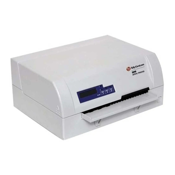
TallyGenicom 5040 User Manual
Flatbed printer
Hide thumbs
Also See for 5040:
- User manual (142 pages) ,
- Product manual (12 pages) ,
- Quick start manual (15 pages)
Table of Contents
Advertisement
Quick Links
Advertisement
Table of Contents

Related Manuals for TallyGenicom 5040


Summary of Contents for TallyGenicom 5040
- Page 1 5040 User Guide Flatbed Printer...
- Page 2 TRADEMARK ACKNOWLEDGEMENTS • Centronics is a trademark of Centronics Data Computer Corporation. • PCL and PCL6 are trademarks of Hewlett-Packard Company. • IBM and IBM PC are trademarks of International Business Machines Corporation. • Apple, AppleTalk, TrueType, Laser Writer and Macintosh are trade-marks of Apple Computer, Inc. •...
-
Page 3: Table Of Contents
User guide Table of contents Table of contents Introduction Printer features Interfaces Emulations Symbols used About this manual Printer at a glance View from the front View with cover opened View from the rear Installation Unpacking the printer Placing your printer Checking the printer voltage Connecting the printer Switching on the printer... - Page 4 Table of contents User guide Control panel Display, indicators and keys Status indicators Status indicator variations Ready indicator (STOP LED) Paper indicator (PAPER LED) User 1 and User 2 indicators Key functions during operation STOP/EJECT key USER 1 and USER 2 key Key functions when powering on STOP/EJECT key USER 2 key...
- Page 5 User guide Table of contents Menu Programming using the control panel Calling up the menu Menu configurations (User 1/User 2) Menu handling Key functions USER 1 key USER 2 key STOP/EJECT key Setting parameters (principle) Terminating menu mode Selecting the LC display language Printing out the status page Power on + USER 2 key Print out status page in menu mode...
- Page 6 Table of contents User guide Error messages and warnings Unrecoverable errors Recoverable errors Print Head Hot Error Ribbon Cassette Error Paper Length Error Framing Error (Serial I/F) Parity Error (Serial I/F) Overrun Error (Serial I/F) Cover Open Error Cover Open Error Warnings Data in Buffer Remove Paper...
- Page 7 User guide Table of contents IBM code pages Code page 437 Code page 850 Code page 860 Code page 863 Code page 865 Code page 851 Code page 852 Code page 853 Code page 855 Code page 857 Code page 866 Code page 869 Code page USSR Gost Code page 864...
- Page 8 Table of contents User guide Interfaces Interface settings for User 1 and User 2 Parallel interface Connector assignment Nibble Mode ECP mode Serial interface RS232C Connector assignment Serial attachment characteristics Data rates Supported protocols Data Transfer Parity Handshake Ready/Busy (Hardware Handshake) XON/XOFF (Software Handshake) Configuring the serial interface of the PC DOS mode/Command line...
-
Page 9: Introduction
User guide Introduction Introduction Printer features This printer is a document printer for printing manually inserted docu- ments as well as passbooks (vertical and horizontal fold passbooks). Manual insertion of the documents is supported by an automatic doc- ument alignment function. The printer has a high processing speed and compact design. -
Page 10: About This Manual
Introduction User guide About this manual This user guide contains a detailed description of the printer, its characteristic features and additional information. Chapter 1 lists all the parts of the printer. Printer at a glance Chapter 2 contains start-up instructions and points to Installation note. -
Page 11: Printer At A Glance
User guide Printer at a glance Printer at a glance View from the front Cover Power switch (On/Off) Control panel Paper tray View with cover opened Ribbon cassette Release lever Print head... -
Page 12: View From The Rear
Printer at a glance User guide View from the rear Power 1st Serial inlet interface interface Parallel 2nd Serial interface interface (special version) -
Page 13: Installation
User guide Installation Installation Unpacking the printer Place your packaged printer on a solid base. Make sure that the “Up” symbols is pointing up. Open the packaging, lift the printer out of the cardboard box and re- move the remaining packaging material. Check the printer for any visible transport damage and missing items. -
Page 14: Placing Your Printer
Installation User guide Placing your printer Place the printer on a solid, flat, surface, ensuring that the printer is po- sitioned in such a way that it can not topple, and that there is easy access to the control panel and paper input tray. Also ensure there is sufficient space for the printed output. - Page 15 User guide Installation When selecting the printer location, observe the following additional instructions: Never place the printer in the vicinity of inflammable gas or STOP explosive substances. Protect the printer from shock, impact and vibration. Be sure to connect the printer to a socket with the correct mains voltage.
-
Page 16: Checking The Printer Voltage
Installation User guide Checking the printer Make sure that the device has been set to the correct voltage (e.g. 230 V in Europe, 120 V in the USA). To do this, check the type plate at the voltage back of the printer. Contact your dealer if the setting is incorrect. Never switch on the printer if the voltage setting is incorrect, STOP since this may result in severe damage to the printer. - Page 17 User guide Installation Make sure that the printer and the computer are switched off and connect the data cable between the printer and the computer. This example shows a 36-pin centronics parallel cable.
-
Page 18: Switching On The Printer
Installation User guide Switching on the Before switching the printer on, make sure that it is connected correctly and that you have followed all the safety and installation instructions printer (see section , page 6). Placing your printer Press the power switch which is located at the front bottom right of the printer to switch on the printer. -
Page 19: Printer Drivers And Firmware
User guide Printer drivers and firmware Printer drivers and firmware Printer drivers You must install a printer driver so that the printer can process the data from your application programs. An original driver offers the best conditions for optimal printing re- sults. -
Page 20: Installing A Printer Driver In Windows 2000/Xp
Printer drivers and firmware User guide Select the port to which your printer is connected, then click on Next. If required, edit the name of the default printer and specify whether you wish to use the printer as a default printer by clicking on the relevant option. -
Page 21: Other Operating Systems
User guide Printer drivers and firmware Open the folder of your printer’s operating system, select the file OEMPRINT.inf and click on OK. Select the printer type. Click on OK, then on Next. If required, edit the name of the default printer and specify whether you wish to use the printer as a default printer by clicking on the relevant option. -
Page 22: Form Settings (Windows 2000/Xp)
Printer drivers and firmware User guide In contrast to Windows versions 95/98, in which forms are defined in Form settings (Windows the printer driver itself, Windows versions 2000/XP have a central fa- 2000/XP) cility for managing form properties and assign one paper feed only. If you want to set up a form not included in the Windows default set- tings, proceed as follows. -
Page 23: Loading Firmware
User guide Printer drivers and firmware Loading firmware The most current version of the firmware can be downloaded from our . There you will find also additional informations regarding Internet site the firmware and printer upgrades. Make sure that the download con- sists of the following files: Standard Model PB Flash VX.XX.exe: the memory writer (flash) BL_XXXX.IPL: Bootblock of the printer... -
Page 24: Usb Interface (Windows2000/Xp)
Printer drivers and firmware User guide USB interface (Windows2000/XP) Make sure that the USB interface is selected in the printers menu for User 1, that a printer driver has been installed and the printer is defined as default printer. To load new firmware to the printer, proceed as follows. As mentioned Downloading firmware to before it is important that no other device (printer) is set to the inter- the printer... -
Page 25: Control Panel
User guide Control panel Control panel The control panel allows the user to set some functions in the printer and set up the basic printer parameters on installation. The control pan- el is located on the front right side of your printer and consists of a two- line LC display with 2 x 16 digits, three keys for controlling the printer functions and four LED indicators displaying the status of the printer. -
Page 26: Display, Indicators And Keys
Control panel User guide Display, indicators and keys PAPER USER1 USER2 STOP /EJECT SETUP LCD display: Displays the internal printer status, operating instructions and error messages. Paper LED: Indicates whether paper is loaded; on = paper is inserted, off = no paper inserted; blinking = indicates that data has been sent to the printer. -
Page 27: Status Indicators
User guide Control panel Status indicators This section defines the status of the control panel. The LED lights Status indicator variations will be on, off or blinking coupled with messages from the LCD. In this way the printer reports its current status. Ready Paper User 1 User 2 LCD Indicated Printer Status —... -
Page 28: Ready Indicator (Stop Led)
Control panel User guide Ready indicator (STOP LED) Ready indicator (STOP LED) not lit: PAPER The printer is in the stop status (Offline) and will not receive data from the system. USER1 STOP USER2 /EJECT SETUP Ready indicator (STOP LED) lit: PAPER The printer is switched on in the online status. -
Page 29: Paper Indicator (Paper Led)
User guide Control panel Paper indicator (PAPER LED) Paper indicator (PAPER LED) does not light: PAPER No paper is inserted in the printer. USER1 USER2 STOP /EJECT SETUP Paper indicator (PAPER LED) lights: PAPER Paper is inserted in the printer. USER1 USER2 STOP... -
Page 30: User 1 And User 2 Indicators
Control panel User guide The USER 1 and USER 2 LEDs are normally under the control of the User 1 and User 2 indicators application. They are available to indicate to the user that the appropri- ate interface is active. Normally in Olivetti, IBM or Epson (Auto)em- ulations, with dual host connections they will indicate that a job is available for the interface associated with the USER. -
Page 31: Key Functions During Operation
User guide Control panel Key functions during operation STOP/EJECT key With the Ready indicator lit, the printer is PAPER ready to recieve data from the host. You can switch the printer from online to offline by pressing the STOP/EJECT key. USER2 USER1 STOP... -
Page 32: User 1 And User 2 Key
Control panel User guide USER 1 and USER 2 key The USER 1 and USER 2 keys are by default PAPER inactive. They must be activated via an appli- cation. The functionality of the keys then de- pend on the selected emulation and the USER1 USER2 STOP... -
Page 33: Key Functions When Powering On
User guide Control panel Key functions when powering on STOP/EJECT key Powering on the printer whilst holding the STOP/EJECT key will activate “Hex Dump” mode. Keep the STOP pressed until the message Hex Dump NO PAPER ap- PAPER pears on the LCD display. USER1 USER2 STOP... -
Page 34: User 1 Key
Control panel User guide USER 1 key Powering on the printer whilst holding the USER1 key will allow you to enter menu mode. Keep the USER key pressed until the message MENU USER appears on the LCD PAPER display. USER1 USER2 STOP /EJECT... -
Page 35: Key Functions In Menu Mode
User guide Control panel Key functions in In menu mode the control panel keys have the following functions menu mode USER 1 key The USER1 key is used to go to the next pa- PAPER rameter group or next parameter on the same menu level (symbolized by an arrow pointing upwards). -
Page 37: Print Media
User guide Print media Print media Inserting a document Before inserting a document make sure that the printer is switched on and the the message ONLINE NO PAPER is displayed in the LCD (see , page 10). Switching on the printer Insert the document in such a way that the right paper edge is positioned inside the area between the left side of the symbol and the... -
Page 38: Inserting A Passbook
Print media User guide Inserting a passbook Before processing a new vertical-fold or horizontal-fold passbook, you should eliminate the stiffness of the fold by proceeding as follows. Open the passbook on the page that you want to print. Bend the fold backwards extremely hard. - Page 39 User guide Print media The bulge of the opened passbook should be as flat as possible to ensure trouble-free trans- portation into the paper. Place the passbook on the right-hand side of the document support with the page to be printed facing up.
-
Page 40: Removing Media
Print media User guide After the passbook is printed, it should be au- tomatically ejected from the printer and re- leased for removal. If the passbook has not successfully ejected from the printer, press the STOP key to to take the printer to STOP (Offline) mode: press the STOP key again to eject the passbook. -
Page 41: Changing The Ribbon Cassette
User guide Changing the ribbon cassette Changing the ribbon cassette Make sure that the printer is switched off before replacing the ribbon cassette. The print head may be hot if the printer has been printing for a STOP long time. Wait until it cools to a temperature safe for handling. Removing the ribbon cassette Open the top cover by grasping it at the right and left-hand sides and swing upward until it... - Page 42 Changing the ribbon cassette User guide Remove the colored ribbon guide from the print head by pulling it downwards. Raise the front end of the ribbon cassette on both sides. Take the ribbon cassette out of the printer. Ensure proper disposal of used ribbon cassettes in accordance with the applicable national laws and regulations.
-
Page 43: Inserting The Ribbon Cassette
User guide Changing the ribbon cassette Inserting the ribbon Take the new ribbon cassette from the packaging and remove the trans- portation lock which fixes the ribbon guide to the cassette. cassette First insert the new ribbon cassette by hook- ing it into the rear slots of its mountings. - Page 44 Changing the ribbon cassette User guide Pull the ribbon guide under the print head. Tighten the ribbon by turning the tension gear in the direction of the arrow (see image be- low). Press the ribbon guide onto the print head from underneath until you hear it click into place.
- Page 45 User guide Changing the ribbon cassette Close the main frame by pressing the colored section in the middle of the frame as shown and ensure both left and right hand sides of the frames are fully latched. Close the cover. The printer is now ready to operate and to be switched on again.
-
Page 47: Replacing The Print Head
User guide Replacing the print head Replacing the print head As the print head has a very long life, under normal circumstances it rarely needs replacing. Always take care not to print over the edge or on a fold or perforation, STOP as this can damage the needles of the print head. - Page 48 Replacing the print head User guide Press the green release lever for the printing mechanism. This swings the printing mecha- nism backwards. If the printer has been printing STOP for a long time, the print head can be hot. Wait until it has cooled to a temperature suitable for handling.
- Page 49 User guide Replacing the print head Remove the two outside located screws from the print head. Disconnect the two flexible cables from the print head. Now remove the print head from its mounting by easing it forward. Ensure proper disposal of the print head in accordance with the applicable national laws and reg- ulations.
-
Page 50: Inserting New Print Head
Replacing the print head User guide Inserting new print head Ease the new print head down into the mounting. Set the print head onto the center of area Fasten the two screws Connect the flexible cables to each connec- tor. Make sure to push them fully into the con- nectors;... - Page 51 User guide Replacing the print head Pull the ribbon guide under the print head. Tighten the ribbon by turning the tension gear in the direction of the arrow (see image be- low). Press the ribbon guide onto the print head from underneath until you hear it click into place.
- Page 52 Replacing the print head User guide Close the main frame by pressing the colored section in the middle of the frame as shown and ensure both left and right hand sides of the frames are fully latched. Close the cover. The printer is now ready for operation and can be switched on again.
-
Page 53: Menu
User guide Menu Menu Programming using the As well as being able to control your printer via your applications soft- ware you use, you can also program the printer directly. There are two control panel programming options you can use: Programming via the control panel. -
Page 54: Calling Up The Menu
Menu User guide Calling up the menu You can access the menu in the following way: Ensure the printer is powered off. Power on the printer whilst holding the USER1 key. PAPER USER1 USER2 STOP /EJECT SETUP The printer initialises and the LCD displays the message: PAPER USER2... -
Page 55: Menu Handling
User guide Menu Menu handling You can navigate in the current menu using the three keys of the con- Key functions trol panel. In menu mode the USER 1 key has the following functions: USER 1 key Press the USER 1 key to return to the previ- PAPER ous parameter group or parameter on the same menu level. -
Page 56: Stop/Eject Key
Menu User guide Pressing the USER 2 key again will open the PAPER first parameter group or parameter of the same menu level. USER1 STOP USER2 By pressing the STOP/EJECT key you will /EJECT SETUP return to the previous menu layer (see also , page 48). -
Page 57: Setting Parameters (Principle)
User guide Menu Before you begin setting the parameters, you should check which pa- Setting parameters rameters your system requires. Furthermore it is recommended to print (principle) out the status page which contains the actual valid parameter values (see , page 53). Printing out the status page The initial values, which are activated after switching on or after error correction, are determined using the adjustable printer parameters. -
Page 58: Terminating Menu Mode
Menu User guide Press the USER 2 key to select a next parameter value or press the PAPER USER 1 key to select a previous parameter value. USER1 STOP USER2 /EJECT SETUP Press STOP/EJECT key to save a parameter value. In the second line PAPER of the LCD display the message Accepted appears. -
Page 59: Selecting The Lc Display Language
User guide Menu This section describes how to make settings in the menu, using the se- Selecting the LC display lection of the national language as an example. language This example shows how to change from the English language to the German language. - Page 60 Menu User guide Press the STOP/EJECT key to confirm the PAPER selection. The printer switch to german language imme- USER1 STOP USER2 diately. /EJECT SETUP To change other parameter items in this menu PAPER level, use the USER 1 or USER 2 keys to nav- igate to the respective items.
-
Page 61: Printing Out The Status Page
User guide Menu Printing out the The printer has a function that allows you to printout the current pa- rameter settings. status page There are two ways to print out the parameter settings. Power on + USER 2 key Selection of “Test Print Status Page” in menu mode USER 2 key Power on + Power the printer off. -
Page 62: Print Out Status Page In Menu Mode
Menu User guide When the test printout is aborted or complet- PAPER ed, LCD will display Print StatusPage Com- pleted. USER1 STOP USER2 The Print setting mode will end automatically /EJECT SETUP and a Power ON reset will be performed. Print out status page in menu mode Power the printer off. - Page 63 User guide Menu The paper will be ejected once printing is com- PAPER plete. USER1 STOP USER2 /EJECT SETUP When the test printout is aborted or complet- PAPER ed, LCD will display Print StatusPage Com- pleted. USER1 STOP USER2 Press the STOP/EJECT key to return to /EJECT SETUP menu mode.
-
Page 64: Status Page (Example)
Menu User guide Status page (example) -
Page 65: Menu Parameters
User guide Menu Menu parameters The following section introduces and explains all the possible menu settings. The default setting is marked by an asterisk (*) Parameter group Parameter Possible settings Description MENU Default Set Sets all parameters to the default settings. COMMON Menu 1 sets all parameters of Menu 1 to the Menu 1... - Page 66 Menu User guide Parameter group Parameter Possible settings Description Font Draft This parameter selects the character style. Draft Banking The fonts available depend on the installed Courier character generator. For more information on Roman character generators, refer to Loading firm- Sans Serif ware, page 15 Gothic...
- Page 67 User guide Menu Parameter group Parameter Possible settings Description Top of form pos. 0/60 Sets the position of the first printing line. The factory setting for the first printing position is 10/60 10/60" (4,23 mm). This is equivalent to the second line from the top.
- Page 68 Menu User guide Parameter group Parameter Possible settings Description Paper ejection drop Selects the paper position after paper ejection. hold Message display Selects displaying messages on or off in Olivetti, EPSON and IBM 4722 emulation. NOTE: These messages will not be displayed if IBM Proprinter XL is selected as Emulation Type.
- Page 69 User guide Menu Parameter group Parameter Possible settings Description Protocol Ready/Busy Selects the type of protocol, i.e. a certain set of Xon/Xoff rules and procedures for ensuring error-free data exchanges between computer and printer. Details of the available protocols can be found in the section Serial attachment characteristics, page 131.
- Page 70 Menu User guide Parameter group Parameter Possible settings Description MENU Emulation type US-ASCII Selects the national character set in Epson Epson France emulation. The character sets are not neces- Germany sarily available for all fonts; see also section Great Britain Available code pages and fonts, page 104.
-
Page 71: Test Function
User guide Menu Test function Hex Dump With the interface mode (Hex-Dump/H-Dump) you can diagnose data transmission from the computer to the printer. In this special mode, the data from the computer is printed out in two columns. The text in the left column is printed in hexadecimal format and in the right column in ASCII format. -
Page 72: Exiting The Test Mode
Menu User guide If the printer receives data when there is no PAPER paper in the printer, the message will be changed to Hex Dump Load Paper. USER1 STOP USER2 /EJECT SETUP You can only exit the test mode by switching off the printer. Exiting the test mode Test printout Hex Dump Address... -
Page 73: Troubleshooting
User guide Troubleshooting Troubleshooting Many of the faults and problems which may occur while using the printer are minor problems which you can solve yourself. The follow- ing chapter should help you to distinguish between a simple operating error and a major malfunction. This chapter provides information on the rectification of faults without the assistance of specially trained personnel. -
Page 74: General Print Problems
Troubleshooting User guide General print problems Problem Corrective action The display remains dark Switch off the printer and proceed as follows: The printer is switched on, but noth- Check that the power plug is correctly connected to the socket ing happens (nothing is displayed, on the printer. -
Page 75: Problems With Paper Feed
User guide Troubleshooting Problem Corrective action Check that the correct media type is selected in the menu, if Problems with paper feed necessary select the correct media type. See section Media Paper will not load or feed page 59. Check if the right edge of the document is positioned inside the area between the left side of the symbol and the right edge of the document support. -
Page 76: Problems With The Print Quality
Troubleshooting User guide Problems with the print quality Problem Corrective action Print is faulty The inserted document is too thick. Use a document with the cor- rect thickness. Refer to the section , page 85 Paper specifications and the chapter , page 29. -
Page 77: Error Messages And Warnings
User guide Troubleshooting Error messages and Malfunctions are differentiated as warnings and errors. For a warning a message only appears on the LCD briefly. warnings As soon as the control logic of the printer detects an error, it aborts the printout and the Ready and the Paper indicators on the control panel starts to blink. -
Page 78: Unrecoverable Errors
Troubleshooting User guide The following errors are unrecoverable by the user. If displayed in the Unrecoverable errors LCD display, power the printer off and on again. CAM Error Carrier Error RAM Error ROM Error EPROM Error CG Error MSR-H Error Key Scan Error If the error message appears again after you have repeatedly powered the printer off and on, contact your dealer or customer... -
Page 79: Recoverable Errors
User guide Troubleshooting Recoverable errors Message Condition Corrective action Power the printer off, open the cover Print Head Hot The print head is too hot. and wait a few minutes. Then power Error the printer on again. Check if the ribbon cassette is in- Ribbon Cassette Either the ribbon cassette is not stalled correctly (see section... -
Page 80: Framing Error (Serial I/F)
Troubleshooting User guide Message Condition Corrective action If STOP/EJECT key is pressed, the Framing Error The Stop bit is not detected by the error message is canceled and the (Serial I/F) serial interface. printer is in offline (STOP) state. “?” is printed instead of the received data until the error is canceled. -
Page 81: Warnings
User guide Troubleshooting Warnings Message Condition Corrective action USER 2 key When the above-mentioned condi- Data in Buffer USER 1 or is pressed in tion occurs, LCD Message is dis- online state and there is data in the played "Warning Data in buffer" for print buffer. -
Page 82: Clearing Paper Jams
Troubleshooting User guide Clearing paper jams If a document which was fed into the printer is not automatically eject- ed or ejected after pressing the STOP/EJECT key on the control panel after its processing, a paper jam has occurred inside the printer and is displayd in the LCD display. - Page 83 User guide Troubleshooting Press the two green release levers on both sides of the panel and lift the panel up. Then remove the jammed paper by pulling it in di- rection of the arrow out of the printer. Close the main frame by pressing the colored section in the middle of the frame as shown by the white arrow and ensure both left and right hand sides of the frames are fully latched.
-
Page 85: Care And Maintenance
User guide Care and maintenance Care and maintenance The printer is designed to operate with minimal maintenance. It is ad- visable to clean the inside of the printer from time to time with a vacu- um cleaner. Before cleaning, turn off the printer, wait 5 to 10 seconds and discon- STOP nect the power cable. -
Page 86: Cleaning The Msr-H Magnetic Stripe
Care and maintenance User guide Cleaning the MSR-H If your printer has an MSR magnetic stripe reader, the MSR read/write head can be cleaned with a special cleaning sheet as follows. magnetic stripe Press the USER 1 and USER 2 key and keep the key pressed while switching on the printer. - Page 87 User guide Care and maintenance After finishing the cleaning process the LCD PAPER displays the Message MSR-H Cleaning OK. You can repeat the cleaning routine by press- USER1 STOP USER2 ing the STOP/EJECT key. /EJECT SETUP If an error occurs during the cleaning process, PAPER the LCD displays the message MSR-H Cleaning Error after the cleaning action has...
-
Page 88: Transport Of The Printer
Care and maintenance User guide Transport of the printer If you intend to transport the printer over a short distance only, ensure Preparations for transport that it has been switched off correctly. Never remove the mains plug when you can still hear mechanical STOP noise. -
Page 89: Specifications
User guide Specifications Specifications Printer specifications Printer system Serial impact matrix printer Printhead with 24 needles Diameter 0.22 mm Print speed Draft (High Speed) 16.6 17.1 Draft (Normal) 16.6 17.1 Letter Quality (High Speed) 16.6 17.1 Letter Quality (Normal) 16.6 17.1 Tab speed 10 IPS (Inches Per Second) max. - Page 90 Specifications User guide Character pitch 10, 12, 15, 17.1, 20 and 24 (16.6 only for PR2) Fonts Standard CG Draft Draft Draft Banking Courier Roman Sans Serif Script OCR-A OCR-B Optional CGs Bold Gothic Prestige Elite Orator 1) If OCR-A font is selected, the code page will auto- matically select DIN as code page.
- Page 91 User guide Specifications Rated current intake Operation (maximum): US: 1.30 A; EU: 0.59 A Standby: US: 0.11 A; EU: 0.072 A Apparent power consumption Operation (maximum): US: 89.7 VA; EU: 93.6 VA Standby: US: 8.8 VA; EU: 11.4 VA Noise Sound output level : 7.1 dB in operation Sound pressure level...
- Page 92 Specifications User guide Approvals DIN EN 60 950 / VDE 0805, TUV (EN 60950) / Certified CE Mark, UL 60950 3rd Edition / C-UL (CSA C22.2 No 60950-00) new reversion, IEC 60950-1, EN 55022:1998 (Class B), EN 55024: 1998, FCC PT 15B : 2000 (Class B), EN61000-3-2:2000, EN61000-3-3:1995...
-
Page 93: Paper Specifications
User guide Specifications Paper specifications Single and multi-copy sheet Paper width 70 to 240 mm Paper length 70 to 500 mm Paper weight Single sheet: 60 to 160 g/m Multi sheet: 80 to 260 g/m Paper thickness Single sheet: 0.08 to 0.5 mm Multi sheet: 0.08 to 0.5 mm Number of copies... - Page 94 Specifications User guide Paper quality Light pulp paper of medium fine quality, paper bear- ing the quality mark SM Post and photocopy paper are suitable for use. Unsuitable are: satin-finish or coated papers, imita- tion art papers, and embossed papers. Since paper as natural material reacts strongly to environmental influences (e.g.
-
Page 95: Interface Specifications
User guide Specifications Interface specifications Parallel interface bidirectional Type of data transmission 8-bit parallel interface (Centronics compatible) IEEE-1284; Nibble and ECP mode Transmission rate Max. 30 KHz Signal status Low: 0.0 V to +0.4 V High: +2.4 V to +5.0 V Connection cable Material: AWG 28 at least Length: up to 2.0 m... -
Page 97: B Character Sets
User guide Character sets Character sets This chapter shows the character sets and contains a list of all available character sets which can be selected via control panel or by escape se- quences. The following example shows you how to find the hexadecimal value for a character from the symbol set tables. -
Page 98: Ocr-A Character Set
Character sets User guide OCR-A character set... -
Page 99: Epson Character Sets
User guide Character sets Epson character sets Italic Graphic1... -
Page 100: Graphic2
Character sets User guide Graphic2... -
Page 101: Ibm Code
User guide Character sets IBM code pages Code page 437 Code page 850... -
Page 102: Code
Character sets User guide Code page 860 Code page 863... -
Page 103: Code
User guide Character sets Code page 865 Code page 851... -
Page 104: Code
Character sets User guide Code page 852 Code page 853... -
Page 105: Code
User guide Character sets Code page 855 Code page 857... -
Page 106: Code
Character sets User guide Code page 866 Code page 869... -
Page 107: Code Page Ussr Gost
User guide Character sets Code page USSR Gost Code page 864... -
Page 108: Code Page 437G
Character sets User guide Code page 437G Code page 920 (equivalent to ISO 8859-9) -
Page 109: Code Page 923 (Equivalent To Iso 8859-15)
User guide Character sets Code page 858 Code page 923 (equivalent to ISO 8859-15) -
Page 110: Iso Code Pages
Character sets User guide ISO code pages ISO 8859-2 ISO 8859-5... -
Page 111: Iso 8859-7
User guide Character sets ISO 8859-7 ISO 8859-8... -
Page 112: Available Code Pages And Fonts
Character sets User guide Available code pages The following list includes all the character sets you can select from the control panel or via ESC sequences and specifies the fonts in which and fonts they are available. The printer does not support all code pages in all the fonts. See the Code page table and notes. - Page 113 User guide Character sets Draft Sans Orator- Code page/Font Draft Roman Courier Bold Prestige Script Orator Gothic OCR-A OCR-B Banking Serif CP 923 (equivalent to ISO 8859-15) ISO 8859-1 Latin 1 ISO 8859-2 Latin 2 ISO 8859-5 Cyrillic ISO 8859-7 Greek ISO 8859-8 Hebrew 1250 Windows...
-
Page 115: C Emulations
User guide Emulations Emulations When a printer understands the control set written for another printer type, it is said to emulate the other printer. Your printer emulates, i.e. “understands” the Olivetti PR2, the Epson and the IBM emulation in its standard version. Escape sequences Escape sequences or control codes tell the printer that the following transmitted code is a printer command and not a printable character. -
Page 116: What Are Escape Sequences
Emulations User guide An escape sequence consists of an ESCape control character (ESC = What are escape decimal 27 or hexadecimal 1B) followed by one or more characters, sequences? which represent commands to the printer. Please note that this escape character has nothing to do with the ESC key on your computer key- board. -
Page 117: List Of Available Control Codes
User guide Emulations List of available control The following table shows the available sequences in the various emu- lations. codes If you want to know more about control codes, we recommend our Programmer’s Application Manual on this CD-ROM. Detailled infor- mation on PR2 control codes can be found in the original PR2 pro- grammer’s manual. - Page 118 Emulations User guide Command sequence Function ESC ` n Superscript - Subscript ESC { Cancel superscript-subscript ESC S 5 Select printer device Line feed forward Form feed (ejection from rear) Carriage return Back Space ESC 7 Line feed back ESC H nnn Set absolute horizontal position ESC I nnn Set relative vertical position...
- Page 119 User guide Emulations Command sequence Function ESC : 000 Copy character generator into user memory ESC m n 0 Select character generator ESC Z Request for primary ID ESC / / Printer ID ESC i Request for basic machine configuration ESC p x y z k Printer configuration ESC j...
- Page 120 Emulations User guide Command sequence Function ESC y dati ESC Z Activate Bar Code Print ESC } + Form position control ESC } L t nnn Passbook positioning ESC } M nnn Negative bottom of form ESC } W Wait for end of print ESC } 0 P Reset form parking ESC s nnnn...
-
Page 121: Pr50 Mode
User guide Emulations PR50 mode Command sequence Function Page Layout ESC Q nnn mmm ESC Z Define document length ESC J nnn Define left margin ESC T nnn Define top of form " TOF" ESC M nnn Define bottom of form "BOF" ESC &... - Page 122 Emulations User guide Command sequence Function ESC O Eject document ESC ^ 0 Change emulation ESC [ nnn Select character set Bell Clear print memory ESC # n Assign reference for ESC L nnn ESC | A nnn Define offset in elementary steps ESC | B nnnn Define document width in elementary steps ESC ' n...
- Page 123 User guide Emulations Command sequence Function Select automatic operator booking ESC _ Select manual operator booking ESC [ c 19 Programming Display command ESC [ c ETX Cancel Programming Display command Magnetic Device Control ESC ] Passbook magnetic stripe read ESC t datiGS Data to be recorded on the magnetic stripe ESC \...
-
Page 124: Pr2845 Mode
Emulations User guide PR2845 mode Function Command sequence Page Layout ESC Q nnn mmm ESC Z Define document length ESC J nnn Define left margin ESC T nnn Define top of form " TOF" ESC M nnn Define bottom of form "BOF" ESC &... - Page 125 User guide Emulations Function Command sequence Bell Clear print memory ESC # n Assign reference for ESC L nnn ESC | A nnn Define offset in elementary steps ESC | B nnnn Define document width in elementary steps ESC ' n Set up document type ESC / m nnnn Absolute vertical position in elementary steps...
- Page 126 Emulations User guide Function Command sequence ESC t datiGS Data to be recorded on the magnetic stripe ESC \ Record and verify magnetic stripe ESC } r MICR magnetic read ESC Y E k1 K2 Set horizontal magnetic device ESC Y B k1 K2 Set MICR Magnetic Read External paper handling device control ESC } +...
-
Page 127: Ibm Mode
User guide Emulations IBM mode Command sequence Functions Horizontal position control Backspace Horizontal tab Carriage return ESC BS 1BH 08H Backspace ESC HT 1BH 09H Horizontal tab ESC CR 1BH 0DH Carriage return ESC D 1BH 44H Set horizontal tabs ESC X 1BH 58H Set horizontal margins... - Page 128 Emulations User guide Command sequence Functions ESC ] 1BH 5DH Reverse line feed Double-wide printing by line Condensed printing Select 10 cpi Cancel double-wide printing by line ESC SO 1BH 0EH Double-wide printing by line ESC SI 1BH 0FH Condensed printing ESC DC2 1BH 12H Select 10 cpi...
- Page 129 User guide Emulations Command sequence Functions ESC L 1BH 4CH Dual density bit image graphics ESC Y 1BH 59H Dual density bit image graphics ESC Z 1BH 5AH High density bit image graphics ESC [ g 1BH 5BH 67H High resolution graphics Barcode ESC [ f 1BH 5BH 66H...
-
Page 130: Epson Mode
Emulations User guide Epson mode Command sequence Function Horizontal position control Backspace Horizontal Tab Carriage Return ESC $ 1BH 24H Set Absolute Print Position ESC D 1BH 44H Select Horizontal Tabs ESC Q 1BH 51H Set Right Margin ESC \ 1BH 5CH Set Relative Print Position ESC a... - Page 131 User guide Emulations Command sequence Function Cancel Condensed Mode Cancel Double-Wide Printing 1 Line ESC SO 1BH 0EH Double-Wide Printing 1 Line ESC SI 1BH 0FH Select Condensed Mode ESC ! 1BH 21H Master Select ESC ( - 1BH 28H 2DH Select Score ESC - 1BH 2DH...
- Page 132 Emulations User guide Command sequence Function Bitimage ESC * 1BH 2AH Select Graphics Mode ESC ? 1BH 3FH Reassign Graphics Mode ESC K 1BH 4BH Select Single-density Graphics Mode ESC L 1BH 4CH Select Double-density Graphics Mode ESC Y 1BH 59H Select High-speed Double-density Graphics Mode ESC Z 1BH 5AH...
- Page 133 User guide Emulations Command sequence Function ESC [ # r STX .. ETX 1BH 5BH 23H 72H Writing a MSR track 02H...03H ESC [ % r 1BH 5BH 25H 72H Deleting a MSR track ESC [ n ! t 1BH 5BH n 21H 74H Setting control points/initializing the control cycle ESC [ "...
-
Page 135: D Interfaces
User guide Interfaces Interfaces Your printer offers the possibility of operating either via a parallel, a serial or a USB interface. There is also a printer model with a second serial interface. This chapter informs you about the interfaces and describes the communication between your computer and the printer. -
Page 136: Parallel Interface
Interfaces User guide Parallel interface The bidirectional parallel interface offers the so called “nibble” and the ECP mode of the IEEE1284 interface standard. This enables installa- tion in accordance with Windows “Plug & Play”. The standard parallel interface is able to transfer data at a speed of max. 30,000 bytes per second. -
Page 137: Ecp Mode
User guide Interfaces ECP mode Signal In/Out Parallel In/Out HostClk Signal GND DATA0 Bi-Di Signal GND DATA1 Bi-Di Signal GND DATA2 Bi-Di Signal GND DATA3 Bi-Di Signal GND DATA4 Bi-Di Signal GND DATA5 Bi-Di Signal GND DATA6 Bi-Di Signal GND DATA7 Bi-Di Signal GND... -
Page 138: Serial Interface Rs232C
Interfaces User guide Serial interface RS232C Your printer’s serial interface supports the RS232C specification. The signals are received and transmitted by a 9 pin male connector. Use a serial interface cable that meets the requirements of your host PC. Type RS232C interface Synchronization Asynchronous... -
Page 139: Serial Attachment Characteristics
User guide Interfaces Serial attachment Data rates characteristics The interface supports the following data rates. 4800 bps 9600 bps 19200 bps 38400 bps Supported protocols This interface will also support the following: 7 or 8 Data Bits Even, Odd, None Parity 1 or 2 Stop Bit(s) Ready/Busy or XON/XOFF handshaking Data Transfer... -
Page 140: Handshake
Interfaces User guide Handshake Handshaking in the serial environment is most commonly handled by software and/or hardware. The manipulation of the hardware hand- shaking is handled by the following 4 lines: RTS (Request to Send) CTS (Clear to Send) DSR (Data Set Ready) DTR (Data Terminal Ready) Ready/Busy (Hardware Handshake) When Ready/Busy protocol is selected, DTR will be used to pace the... -
Page 141: Configuring The Serial Interface Of The Pc
User guide Interfaces Configuring the serial DOS mode/Command line interface of the PC To use the serial interface of your PC, you must add the following mode commands to the AUTOEXEC.BAT file: mode com1:9600,n,8,1,p mode lpt1:= com1: With the first MODE command, you configure the serial interface Com1 of your PC to the printer’s factory defaults. -
Page 142: Usb Interface
Interfaces User guide USB interface The USB (Universal Serial Bus) interface has the following features: Full compliance with the Universal Serial Bus Specification Revision 2.0 for Full Speed Mode. USB Function Controller with two FIFO-based Endpoints: One bidirectional Control Endpoint 0 (8 bytes) One receive Endpoint 1 (1*64 bytes) The signaling bit rate is 12 MB/s (Full speed). -
Page 143: E Consumables And Accessories
User guide Consumables and accessories Consumables and accessories Consumables Only use ribbon cassettes from the manufacturer as products from other manufacturers may damage the print head or the ribbon drive. Consumables Order no. Ribbon in recyclable cassettes, color: black 043393 Accessories Only use print heads that are approved to prevent damage to your printer. - Page 145 “All rights reserved. Translations, reprinting or copying by any means of this manual complete or in part or in any different form requires our explicit approval. We reserve the right to make changes to this manual without notice. All care has been taken to en- sure accuracy of information contained in this manual.
- Page 146 #08-22, Lam Soon Industrial Building No 14 Jalan 19/1 46300 Petaling Jaya Singapore 669569 Phone: +65 6760 8833 Selangor Darul Ehsan Fax: +65 6760 1066 Malaysia http://www.tallygenicom.com.sg Phone: +3 7625 1988 Fax: +3 7625 2688 http://www.tallygenicom.com.my © December 2006 TallyGenicom AG...
Need help?
Do you have a question about the 5040 and is the answer not in the manual?
Questions and answers