Table of Contents
Advertisement
Quick Links
Download this manual
See also:
Installation Manual
Advertisement
Table of Contents

Related Manuals for TallyGenicom 2440


Summary of Contents for TallyGenicom 2440
- Page 1 ® User Guide 2440 2540 Matrix Printer...
- Page 2 TRADEMARK ACKNOWLEDGEMENTS “IBM” is a trademark of International Business Machines Corporation. “EPSON” is a trademark of Epson America Incorporated. “DEC” is a trademark of Digital Equipment Corporation. “Centronics” is a trademark of Centronics Data Computer Corporation. “DOS” is a trademark of Microsoft Corporation. “Windows”, “Windows 95”, “Windows 98“, “Windows NT”, “Windows 2000”, “Windows 2003 Server”, “Windows XP”...
-
Page 3: Table Of Contents
Printer components Front view Rear view Internal view Operations of the Control Panel LED indicators Control panel keys Print quality key Print qualities 9 needle printer Print qualities 24 needle printer Character pitch key Table of contents 2-10 2-11 2-12 2-12... - Page 4 Table of contents Paper handling Paper types Paper Specifications Paper Size Paper Thickness and Number of Copies Loading paper Overview of Paper Operations Paper select lever Print Gap Lever Fanfold paper Unloading Continuous Forms Single sheets Ejecting Single Sheets Paper Parking Function Switching from fanfold paper to single sheets Switching from single sheets to fanfold paper Feeding and Positioning Paper...
- Page 5 Setting of The First Dot Position on the Left Side Menu access Setting Setup Mode to Default Value (Standard) Chapter 5 Maintenance Cleaning Cleaning and Vacuuming the Printer Cleaning the Paper Rollers Replacing the Ribbon Cartridge Removing the Ribbon Cartridge Installing the Ribbon Cartridge Replacing the Print Head...
- Page 6 Table of contents Chapter 6 Troubleshooting Solving problems Print Quality Problems and Solutions Paper Handling Problems and Solutions Operating Problems and Solutions LED states in error conditions Printer Failures Diagnostic Functions Chapter A Specifications Printer specifications Paper specifications Print Area Continuous forms...
- Page 7 Serial Interface Timings Serial Interface Error Handling Data rates Configuring the serial interface of the PC Auto Select Interface Chapter C Command Sets 9 wire printer Printer basic functions Emulation Command list Printer unique commands 24 wire printer Printer basic functions...
- Page 8 Table of contents 24 wire printer Non scalable fonts Scalable Fonts and Code Pages Chapter E Supplies and Options Supplies Options Interface Modules...
-
Page 9: Introduction
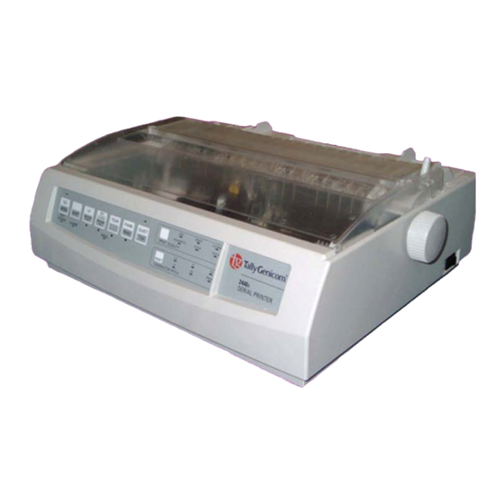
Introduction Congratulations on purchasing the TallyGenicom Matrix Printer 2440/2540. The printer is equipped with a small printhead, which allows printing in fast draft mode, draft mode and letter quality. The printer lends itself to a wide range of applications, accepting a variety of data from host computers. -
Page 10: Features
Various character sets. For IBM Mode: IBM Set 1 and Set 2. For EPSON Mode: 15 • National Character Sets. Multiple fonts. The 9 pin printer has six resident fonts: High Speed Draft, Draft, • Courier, Quadrato, OCR-B, OCR-A. The 24 pin printer has twelve resident fonts: HS Draft, Draft, Roman, Sans Serif, Courier, OCR-B, OCR-A, Prestige, Script, Orator, Gothic, Souvenir. -
Page 11: Symbols Used
Symbols used Important information is highlighted in this manual by three symbols. NOTE: A note is a tip or extra information that may be helpful in installing or using the printer. CAUTION: A caution message provides information that may help you avoid equipment damage, process failure, or inconvenience. -
Page 12: Important Safety Instructions
Read the following instructions thoroughly before starting up your printer in order to pre- vent injuries and avoid damage to the device. Place the printer on a solid and even base so that it cannot fall down to the ground. •... -
Page 13: Operating The Printer
Overview This chapter explains how to operate the printer. Topics covered are: Setting up your printer • Getting to know the printer’s major parts and the control panel • Selecting paper • Overview of paper operations • Adjusting for paper thickness •... -
Page 14: Setting Up Your Printer
Place your packaged printer on a solid base. Make sure that the “Up” symbols point in the correct direction. Open the packaging, lift the printer out of the cardboard box and remove the remaining packaging material. Check the printer for any visible transport damage and missing items. The following items... -
Page 15: Placing The Printer
Operating the printer Placing the printer Place the printer on a solid, flat, surface, ensuring that the printer is positioned in such a way that it can not topple, and that there is easy access to the control panel and paper input devices. -
Page 16: Installation Procedure
Setting up your printer Installation procedure When the printer is first taken out of the Tape packaging box, the cover of the printer is taped as shown in the diagram. Remove the tape. Open the cover of the printer and remove the shipping locks. -
Page 17: Installing The Ribbon Cassette
Proceed as follows to install the ribbon cassette. Only use ribbon cassettes from the manufacturer as products from other manufacturers may damage the print head or the ribbon drive. Setting up your printer Remove the ribbon cassette from its packaging. - Page 18 Setting up your printer Operating the printer Insert the recess on the bottom of the ribbon cassette into the holding pin the mounting. Push the cassette into its mounting until it clicks into position. Close the cover of the printer.
-
Page 19: Connecting The Printer
Make sure that the device has been set to the correct voltage (e.g. 120 V in the USA, 230 V in Europe). To do this, check the type plate at the back of the printer. Contact your dealer if the setting is incorrect. -
Page 20: Connecting The Interface Cable
Setting up your printer Connecting the interface cable The printer by default is provided with a parallel Centronics interface and an USB inter- face. For further in-formation about the interfaces, refer to Appendix B, “Interfaces” on page B-1. Switching on the printer... -
Page 21: Printer Components
Operating the printer Printer components This section describes the major parts and controls of the printer and operations of the control panel. Take a moment to become familiar with the printer. Front view Cover Single sheet feeder: to load single sheets. -
Page 22: Rear View
Paper select lever: to select the paper path USB interface: connect the USB cable here Parallel interface: connect the parallel cable here Tractor: to hold and feed continuous forms Power inlet: Connect the power cord here Space for optional interface 2-10 Operating the printer... -
Page 23: Internal View
Operating the printer Internal view Printhead Paper thickness lever: to adjust the print gap for different paper thicknesses. Ribbon cassette Printer components 2-11... -
Page 24: Operations Of The Control Panel
EXIT POWER ALARM Normal mode operation includes everyday operations, such as paper handling, font and character pitch selection. LED indicators The LED lights of the control panel indicate the current status of the printer. MENU SHIFT EXIT POWER ALARM Status POWER On: the printer is switched on. -
Page 25: Control Panel Keys
On: the printer is in a fault status or paper is missing. Off: there is no fault status and paper is inserted. Control panel keys The control panel keys are used for controlling the printer operation. Key functions de- pend on printer status. MENU... - Page 26 9w model: Feeds paper forward in 1/72 inch increments. 24w model: Feeds paper forward in 1/60 inch increments. Press this key combination to printout an overview of the printer configuration. Press this key combination to adjust the position of the first “Setting the first printing line...
-
Page 27: Print Quality Key
Operating the printer Print quality key The printer can print with different print qualities and fonts. The actual selected print quality is displayed by its respective LED light. If you want to change the print quality setting, press the PRINT QUALITY key repeatedly until the desired print quality is set. -
Page 28: Character Pitch Key
RESET CHARACTER PITCH The printer can print with 10, 12, 15, 17.1 or 20 characters per inch. If PROP (propor- tional spacing) is selected, only the actually required space for the character width is used. 2-16... -
Page 29: Paper Handling
Paper handling Paper types The printer can handle either single sheets or continuous forms. Single sheets, also called cut sheets, include envelopes and non-continuous, multipart forms. Continuous forms in- clude labels and multipart forms fed into the printer using the forms tractors. -
Page 30: Loading Paper
Paper handling Loading paper Your printer can process both fanfold paper and single sheets. For information on the supported paper sizes, please refer to the section “Paper types” on page 2-17 and to Appen- dix A, “Paper specifications” on page A-4. -
Page 31: Print Gap Lever
Operating the printer Print Gap Lever The printer can handle paper with different thicknesses, including multipart forms with up to five parts (original plus four copies). For details on paper thickness specifications, please refer to the section “Paper Specifications” on page 2-17 and to Appendix A, “Paper spec- ifications”... -
Page 32: Fanfold Paper
Paper handling Fanfold paper 2-20 Operating the printer Move the paper select lever backward to continuous paper position. If necessary, readjust the Print Gap lever for continuous forms (see section “Print Gap Lever” on page 2-19). Slightly press the single sheet feeder to the right or to the left, until the holding pin comes free from its recess. -
Page 33: Unloading Continuous Forms
Press the PARK key. The continuous forms paper is retracted to the park position. If the paper cannot be retracted in one operation, continue to press the PARK key until the paper is parked. The printer can retract continuous forms-paper by a recommended maximum of 30.48 cm (12 inches) per operation. Paper handling... -
Page 34: Single Sheets
If necessary, readjust the Print Gap lever for continuous forms (see section “Print Gap Lever” on page 2-19). Make sure that the printer is turned on. Raise the single sheet feeder until it locks into its mounting. Align the left paper guide with the mark on the left of the single sheet feeder. -
Page 35: Ejecting Single Sheets
Operating the printer Paper handling Ejecting Single Sheets If you print using software which inserts a form feed at the end of each page, each sheet is ejected automatically upon the completion of the page printing. To manually eject sheets of paper: Press the FF/LOAD key to execute a forward form feed. -
Page 36: Paper Parking Function
If a single sheet is loaded, press the FF/LOAD key. The sheet is ejeceted. Move the paper select lever to the front (user’s direction) to Continuous Paper position. Press the FF/LOAD key again. The printer feeds the fanfold paper to the top of form position. 2-24... -
Page 37: Feeding And Positioning Paper
• the actual physical page length (distance between two perforations for continuous forms). This will allow the printer to know exactly where the print head is and to posi- tion it at the same position when a form feed occurs. -
Page 38: Continuous Forms
The sprocket hole or the vertical perforation. This distance is recommended in order to Avoid print blurs and print pitch disorder Affected by the horizontal perforation. Same as E, however paper feed precision Of the last page is not guaranteed. Operating the printer 6.35 ± 0.3... -
Page 39: Single Sheets
Operating the printer Single sheets Paper Feed Direction Symbol Dimensions 76.2 ~ 297.2 (Narrow) 76.2 ~ 420 (Wide) 9.6 (min) 76.2 ~ 558.8 6.35 (min) 6.35 (min) Print Area Remark Paper width The distance from the rear end to the printable... -
Page 40: Setting The First Printing Line (Tof)
Either transport fanfold paper to the next top of form position or feed an inserted single sheet by pressing the FF/LOAD key. Make sure that the printer is in offline mode; press the SEL key, if necessary. Hold the SHIFT key depressed and use the Micro Feed Down or Micro Feed Up keys to adjust the desired first printing line. -
Page 41: Selecting Tear-Off Mode
Operating the printer Selecting Tear-off mode By default the “Tear” parameter of the printer is set to “Manual”. If you want to transport the paper to tear-off position, you must press the TEAR key. The “Tear” parameter can be set to automatic mode. In this case the paper is transported after a certain duration of time (1, 2, 3, 4 or 5 seconds) automatically to the tear-off posi- tion if the printer does not receive data. - Page 42 Press the SEL/MENU key again to save the new value and exit the setup mode. The printer exits the setup mode and returns to the ready mode. The selected values remain in effect until the next time they are changed.
-
Page 43: Using The Tractor As Pull Tractor
Using the tractor as pull tractor By default the tractor of your printer is mounted at the rear and works as push tractor. You can use the tractor as pull tractor also. Because the paperway is more straight in pull mode this may be useful if you want to print critical paper types. - Page 44 Paper handling If you switch the printer on again, it autmatically detects that the pull tractor is installed. You can now feed continous paper from the slot in the bottom of the printer. After loading paper into the tractor, you must carry out a form feed. For this reason you cannot print on the first form.
-
Page 45: Printing
For a summary of the operation of these keys, see the section “Operations of the Control Panel” on page 2-12 in Chapter 2, “Operating the printer” on page 2-1. Instructions for loading and handling paper are also given in Chapter 2, “Operating the printer”. -
Page 46: Starting Or Stopping Printing
To start printing, make sure that the Ready indicator is lit (the printer is ready). If not so, press the SEL/MENU key to place the printer in the Ready state. Start your print job. -
Page 47: Special Mode
The Normal mode is used for daily operations like paper handling and printing as ex- • plained in Chapter 2, “Operating the printer” and Chapter 3, “Printing”. The Special mode is used to change the printer settings and to test the printer functions. • The following table summarizes the purpose of each function. -
Page 48: Set-Up Mode
Set-Up values. How Set-Up Works The Set-Up mode consists of Set-Up function menus which correspond to several printer settings. Each parameter group generally has many parameters which correspond to the print features to be changed. Each parameter includes many values to be selected. All the Set-Up function menus, parameters and values are printed in a logical sequence on the pa- per when you enter the Set-Up mode, including the usage of keys. -
Page 49: Entering The Set-Up Mode
PRINTER CONTROL The initial printout contains a header, help menu ( The header tells you that the printer is in the Set-Up mode. The help menu provides a quick summary of how to use keys in the Set-Up mode. The <FUNCTIONS> menu... -
Page 50: Overview Of The Set-Up Mode
Set-Up mode Overview of the Set-Up Mode Your Printer has eleven function menus in Set-Up mode. When you press the PARK/PRINT/ previous <FUNCTIONS> menu is printed. PRINTER CONTROL FONT SYMBOL SETS SET-UP INTERFACE NETWORK COMMON (PUSH TRAC) PULL TRACTOR FRICTION RCALL-FACT SAVE&EXIT... - Page 51 The first five PRINTER CONTROL parameters are shown below. <FUNCTIONS> PRINTER CONTROL Press the FF/LOAD/Micro Feed Up/ key to select the option. The printer prints the first value. Repeatedly press the NEXT key or the PREVIOUS key to position the value you require.
-
Page 52: Options With Pre-Determined Values
Press the SEL/MENU key again to save the new value and exit the Set-Up mode. The printer exits the Set-Up mode and returns to the ready mode. The selected values remain in effect until the next time they are changed. -
Page 53: Options With Undetermined Values
This example shows how to change the top margin of the single sheet feeder from 0/ 72 inch to 3/72 inch. Enter the Set-Up mode: Turn the printer off and back on while pressing the SEL/ MENU key. Select the FRICTION function: Wait for the printer to stop printing and press the... -
Page 54: Functions, Parameters And Values
EPSON-EP Selects the same emulation as that IBM XL selected by your software. PORT DEPEND PORT DEPEND: The printer selects 24w EPSON-EP2 emulation according to the active inter- IBM XL24E face (such as serial, USB). See the next PORT DEPEND options. -
Page 55: Font Menu
Special mode FONT menu Parameter Value FONT 9w: DRAFT, COURIER, QUADRATO, OCR-B, OCR-A 24w: DRAFT, ROMAN, SANS SERIF, COURIER, OCR-B, OCR-A, PRES- TIGE, SCRIPT, ORATOR, GOTHIC, SOUVENIR DRAFT FONT NORMAL DRAFT HS DRAFT 10CPI/12CPI/15CPI/ 17CPI/20CPI Set-Up mode Description Selects a font to be active when the power is turned on. -
Page 56: Symbol Sets Menu
Set-Up mode SYMBOL SETS menu Parameter Value IBM SET 1/2 IBM SET1 IBM SET2 CODE PAGE 9w: CRO-ASCII, CP 437, CP 737, CP 850, CP 851, CP 852, CP 857, CP 858, CP 860, CP 861, CP 863, CP 1252, CP 1253, CP 1254, 8859-1, 8859- 1(SAP), 8859-2, 8859-5, 8859- 7, 8859-9, 8859-15... -
Page 57: Set-Up Menu
Unidirectional printing is used for print- ing that needs precise vertical alignment. Unidirectional printing is slower than bi- directional printing. Bi-directional printing: The printer prints in either direction while seeking the next print direction for a shorter print time. The unidirectional com- mand is ignored. -
Page 58: Interface Menu
The printer communicates with the interface from which it first receives data. The interface is active until the input buffer becomes empty. Sets printer to offline or online mode after paper empty. Selects the transmission mode of the parallel interface. -
Page 59: Network Menu
Description Selects the signal indicating that the serial interface is in busy state (buffer is full, printer is out of paper or an error is detected). Valid only if the READY/ BUSY protocol has been selected. Sets the signal DSR (Data Set Ready) valid or invalid. -
Page 60: Common (Push Trac) Menu
Narrow prineter: Select MODE1 for paper widths between 125 and 209 mm and widths narrower as 125 mm. Wide printer: Select MODE1 for paper widths narrower as 125 mm. Select MODE2 for paper widths between 125 and 210 mm. - Page 61 Special mode Parameter TEAR PAPER INITIAL Value Description AUTO 1 SEC/AUTO 2 SEC/ Specifies the (auto) start time of AUTO 3 SEC/AUTO 4 SEC/ tear-off feeding. If e.g. AUTO 3 AUTO 5 SEC/MANUAL SEC is selected, auto tear-off feeding is executed 3 seconds after data transmission from the computer has ended.
-
Page 62: Friction Menu
Narrow prineter: Select MODE1 for paper widths between 125 and 209 mm and widths narrwoer as 125 mm. Wide printer: Select MODE1 for paper widths narrower as 125 mm. Select MODE2 for paper widths between 125 and 210 mm. - Page 63 Special mode Parameter S-SHEET LD Value Description AUTO 1 SEC/AUTO 2 Specifies the (auto) start time of SEC/AUTO 3 SEC/AUTO 4 paper loading. If e.g. AUTO 3 SEC/AUTO 5 SEC/ SEC is selected, auto paper load- MANUAL ing is executed 3 seconds after inserting the paper.
-
Page 64: Recalling Factory Settings (Rcall-Fact)
To exit the set-up mode and save your setting, first select the SAVE&EXIT function and then press the SEL/MENU/EXIT key. Any settings changed while in the Set-Up mode are saved as the new power-on defaults for the printer. The new defaults remain active until you change them again. 4-18 Special mode... -
Page 65: Using The Diagnostic Functions
Using the Diagnostic Functions Print Configuration Function This function prints a list of all the printer’s currently selected values. This function is use- ful for checking the printer settings when you first enter the Set-Up mode or just before you exit. - Page 66 Using the Diagnostic Functions Special mode 4-20...
-
Page 67: Printing Test Function
Do not press any keys alone or in combination, except for pressing the PRINT QUALITY key alone when turning the printer on, to avoid initiating unexpected tests not permitted for the user. The printer starts to print rolling ASCII data as shown below. -
Page 68: Hex Dump Mode
Print the Hex Dump: a) To start Hex Dump printing, send your file or program to the printer. The printer goes online and prints the Hex Dump. -
Page 69: Printing Alignment Adjustment
Turn the printer back on while pressing the LF key. Do not press any keys alone or in combination, except for pressing the LF key alone when turning the printer on, to avoid initiating unexpected tests not permitted for the user. Adjust the vertical print alignment at High Speed:... - Page 70 The new adjustment values of Bi-directional Alignment is printed using 10cpi, Draft. The paper is automatically advance for viewing after the printing is complete. Align Adjust 1 = xx Align Adjust 2 = xx Exit from Printing Alignment Adjustment mode: Turn off the printer. 4-24 Special mode...
-
Page 71: Top Of Form Adjustment Function
Special mode Top of Form Adjustment Function Print positions often change gradually when you use the printer over long periods of time. The ADJUST function allows you to adjust these positions by fine-tuning the Top of Form origin. To enter Top Adjustment Function: a) Make sure that the tractors are loaded with continuous feed paper and that the pa- per select lever is set forward. -
Page 72: Setting Of The First Dot Position On The Left Side
Using the Diagnostic Functions Setting of The First Dot Position on the Left Side Print positions often change gradually when you use the printer over long periods of time. This adjust function allows you to adjust these positions by fine-tuning the Left Margin origin. - Page 73 Special mode Using the Diagnostic Functions ”xx” is new adjustment value. Exit the setting of the first dot position on the left side mode: Turn the printer off to exit this mode. 4-27...
-
Page 74: Menu Access
Do not press any keys alone or in combination, except for pressing the TEAR key alone when turning the printer on, to avoid initiating unexpected tests not permitted for the user. Changing Menu Access: Press the FF/LOAD/Micro Feed Up/ key to print the current menu access value. -
Page 75: Setting Setup Mode To Default Value (Standard)
QUIET keys. Do not press any keys alone or in combination, except for pressing the TEAR, PARK and QUIET key alone when turning the printer on, to avoid initiating unexpected tests not permitted for the user. Exit the setting setup mode to default value (standard): After the setting completes, the printer will automatically restart in the power-up state. -
Page 77: Maintenance
Cleaning The housing and the top cover of the printer help protect it against dust, dirt, and other contaminants. However, paper produces small particles that accumulate inside the printer. This section explains how to clean and vacuum the printer and how to clean the paper bail rollers. - Page 78 Cleaning Open the cover of the printer and the protective cover of the platen and remove the ribbon cartridge. Using a soft vacuum brush, gently vacuum the platen, the print head carriage and shaft, and surrounding areas. You can easily slide the print head to the left or right when the power is off.
-
Page 79: Cleaning The Paper Rollers
To clean the the rollers and the platen: Apply a small amount of water to a soft cloth. Avoid spilling liquid inside the printer. Place the cloth against the platen and manually rotate the platen knob. Repeat this procedure for each roller. -
Page 80: Replacing The Ribbon Cartridge
The print head may be hot if you have been printing recently. STOP Move the print gap lever to position 6. To remove the ribbon cartridge, press the ribbon release levers located on the sides of the cartridge and carefully lift the cartridge out of the printer. Maintenance... -
Page 81: Installing The Ribbon Cartridge
Only use ribbon cassettes from the manufacturer as products from other manufacturers may damage the print head or the ribbon drive. Remove the ribbon cassette from its packaging. Open the printer cover. Adjust the printhead to the center of the print roller. Turn the tension knob ribbon. - Page 82 When placing the new ribbon cartridge on the carriage, make sure that the thin ribbon does not become bunched or folded at the print head. Readjust the print gap to achieve good print quality. Close the cover of the printer. Use the printing test function to check printing. See “Printing Test Function” on page 4- 21 in chapter 4 “Special mode”.
-
Page 83: Replacing The Print Head
The print head may be hot if you have been printing recently. STOP To remove the print head: Turn off the printer. Open the cover and and the protective cover of the platen and remove the ribbon car- tridge (see section “Removing the Ribbon Cartridge” on page 5-4). -
Page 85: Troubleshooting
This chapter is organized as follows: Solving problems • Diagnostic functions • Solving problems The tables in this section describe common printer problems and their solutions. The fol- lowing types of problems are considered: Print quality problems • Paper handling problems •... -
Page 86: Print Quality Problems And Solutions
Solving problems Print Quality Problems and Solutions Poor print quality or other printing problems are often caused by incorrect printer set-up or incorrect software settings. A gradual decrease in print quality usually indicates a worn ribbon. The following table identifies common print quality problems and suggests solu- tions. - Page 87 Solution The top margin is the sum of the printer’s top-of- form setting, the software-specified top margin, and the printer’s TOP-MARGIN setting. Proceed as follows: Make sure that the top-of-form setting is correct.
-
Page 88: Paper Handling Problems And Solutions
Solving problems Paper Handling Problems and Solutions The following table describes common paper handling problems and suggests solutions. See the section “Paper handling” in Chapter 2, “Operating the printer” for detailed procedures on loading and using paper. Problem Paper cannot be loaded or fed. -
Page 89: Operating Problems And Solutions
If not so, use other outlet. Turn the power off. Wait a minute and then turn the printer on again. If the printer still has no power, contact your dealer. Make sure that the Ready indicator is lit. See “Op- erations of the Control Panel”... -
Page 90: Led States In Error Conditions
Paper near end. Normal status A paper jam has all off occured. blinking Prop Paper is loaded all off into the printer blinking and the paper select lever was moved backward or forward. Prop An interface error all off has ocurred while transferring data. -
Page 91: Printer Failures
• Turn the Ready (SEL/MENU) indicator off • Blink the ALARM indicator • Power off and on again the printer, to recover a fatal error. If you cannot resolve the prob- lem, contact your dealer or service partner. Solving problems... -
Page 92: Diagnostic Functions
PRINTING ALIGNMENT ADJUSTMENT allows you to check and, if necessary, • correct theprinter’s vertical print alignment in bi-directional mode. For details on using these functions, all of which are available in the printer special mode, see the section “Using the Diagnostic Functions” in Chapter 4, “Special mode”. Troubleshooting... -
Page 93: Chapter A Specifications
400 cpl 1, 2, 3, 4, 5, 6, 8, 12 lines/inch 2440/9 Up to 144 vertical × 240 horizontal dots per square inch 2440/24 360 vertical × 360 horizontal dots per square inch 10 cpi vertical x horizontal 2440/9 9 x 9... - Page 94 Printer specifications Item Narrow model Fonts 2440/9 2440/24 High Speed Draft, Draft, Roman, Sans Serif, Courier, Barcodes UPC/A, UPC/E, EAN8, EAN13, Code 39, Code 128, Codabar, Interleaved 2 of 5, Industrial 2 of 5, Postnet Character sets ISO USA, ISO UK, ISO France, ISO Germany, ISO Italy, ISO Swe-...
- Page 95 3) Certified, FCC Class B (J subpart of 15) Certified, CE marking, EMC Immunity: IEC61000-4-2 level3, Energy Star Printer specifications Wide model UL 1950 (with deviation 3) Listed, CSA C22.2 NO.950 (with devia- tion 3) Certified, FCC Class B (J...
-
Page 96: Paper Specifications
Paper specifications Paper specifications Only use paper that corresponds to the paper specifications and test new sorts of paper before use. Paper type Continuous Forms Single Sheets Narrow model Width 102–267 mm (4–10.5 in) Length 102 mm (4 in) up to 559 mm (22 in) No. -
Page 97: Print Area
Specifications Print Area This section illustrates the recommended print area for single sheets and continuous forms. Continuous forms Narrow model: Wc 102 to 267 mm (4 to 10.5 in) Wide model: Wc 102 to 381 mm (4 to 15 in) Lc 5.08 to 25.4 mm (0.2 to 1 in) Paper specifications... -
Page 98: Single Sheets
Paper specifications Single sheets Narrow model: Ws 102 to 267 mm (4 to 10.5 in) Wide model: Ws 102 to 381 mm (4 to 15 in) Hs 76 to 364 mm (3 to 14.3 in) Ls 5.08 to 32 mm (0.2 to 1.26 in) Specifications... -
Page 99: Paper Thickness
Specifications Paper Thickness Paper thickness is given by the weight of the paper in either grams per square meter (g/m ) or in pounds per bond (lbs/bond). The following table shows the allowable paper thickness for one-part paper or for each sheet of multipart paper. The total thickness must not exceed 0.35 mm (0.014 inch). - Page 100 Paper specifications Five-Part Carbon-Backed Two-Part Carbon-Interleaved Three-Part Carbon-Backed Carbon-backed: Do not use in high humidity environments. Carbon-interleaved: Avoid using single sheets format in carbon-interleaved. 40–64 g/m (11–17 lbs/bond) Middle 40–64 g/m (11–17 lbs/bond) Middle 40–64 g/m (11–17 lbs/bond) Middle 40–64 g/m (11–17 lbs/bond) Bottom 40–81 g/m...
-
Page 101: Chapter B Interfaces
Your printer offers by default the possibility of operating either via a parallel interface or an USB interface. In addition, a serial interface (RS232C) or an Ethernet interface are available as options. Interfaces may vary from unit to unit depending on which configu- ration is purchased. -
Page 102: Parallel Interface Pin Assignment
Parallel interface Parallel Interface Pin Assignment Pin No. Signal nSTROBE DATA0 DATA1 DATA2 DATA3 DATA4 DATA5 DATA6 DATA7 nACK BUSY SELECT nAUTOFEED Signal GND Chassis GND +5V DC In/Out Pin No. Parallel Signal GND Signal GND Signal GND Signal GND Signal GND Signal GND Signal GND... -
Page 103: Compatible Mode
Direction Description Input This signal is a strobe pulse for reading data (Data 0 to 7). The printer reads data when this signal is low. The pulse width must be 1 µs or more at the receiving ter- minal. Input Data 8 (pin 9) is the mostsignificant bit;... -
Page 104: Nibble Mode
Output Reverse data transfer phase: This signal is set low when the printer is ready to send data to the host. During the data transfer, it is used as data bit 0 (LSB), then data bit Reverse idle phase: This signal is used to indicate that data is available. -
Page 105: Data Transmission Timing
4) Printer initialization occurs at the falling edge of nINIT. In bidirectional mode (nibblemode), this printer can send data to the computer. Data is sent in units of four bits (nibble) using four output signal lines as data paths. The follow- ing outlines one byte of data sent during reverse data transfer phase in nibble mode. -
Page 106: Usb Interface
USB interface USB interface The USB (Universal Serial Bus) interface has the following features: Full compliance with the Universal Serial Bus Specification Revision 2.0 for Full Speed • Mode. USB Function Controller with two FIFO-based Endpoints: • – One bidirectional Control Endpoint 0 (8 bytes) –... -
Page 107: Configuration Descriptor
Number of Interface. Byte 0x00 Value used to select alternate setting for the interface identi- fied in the prior field. Byte 0x02 Number of endpoints used by this interface (excluding End- point 0). Byte 0x07 Class code (Printer class). USB interface... -
Page 108: Endpoint 1 Descriptor
Endpoint 2 Descriptor Offset Field bLength bDescriptorType bEndPointAddress bmAttributes wMaxPacketSize bInterval Size Value Description Byte 0x01 Subclass code (Printer sub- class). Byte 0x01 Receive. Byte 0x00 Index of string descriptor describing this interface. Size Value Description Byte 0x07 Size of this descriptor in bytes. -
Page 109: Serial Interface (Option
Interfaces Serial interface (option) Your printer’s optional serial interface supports the RS232C specification. The signals are received and transmitted by a 25 pin female connector. Use a serial interface cable that meets the requirements of your host PC. Serial attachment characteristics Signal Description for RS232C Pin No. -
Page 110: Serial Interface Timings
If user selects DTR as Busy line, this line will be set high after the serial interface finishes its Reset sequence. However if Ready/busy handshake pro- tocol is selected, this line is used to indicate to PC whether or not Printer is ready to receive any more data. Interfaces... - Page 111 However, PC is not required to detect this initial XON before transmitting data to Printer. Printer transmits an XOFF to indicate to PC that the receive buffer is full. An XON will be transmitted to PC when buffer space is again available, and the printer is ready to receive more data.
-
Page 112: Serial Interface Error Handling
Buffer Overrun • Parity Errors: When a parity error is detected, printer will indicate warning status on the lights Printer continues to receive data. Framing Errors: When a framing error is detected, printer will indicate warning status on the lights. Printer continues to receive data. -
Page 113: Data Rates
Parity will be checked whenever Even of Odd parity is selected. If a parity error is de- tected, PARITY ERROR message will be displayed on the LCD. Printer will continue to receive data. - Page 114 When Ready/Busy protocol is selected, DTR will be used to pace the data flow from PC. When the serial interface is BUSY (Buffer is full, Printer is out of paper or an error is de- tected), DTR will be dropped to indicate to PC that Printer cannot receive any more data.
-
Page 115: Configuring The Serial Interface Of The Pc
Click on the Start button in the Windows taskbar. Click on Printers (Windows 2000) or on Printers and Faxes (Windows XP) to open the printer folder. In the menu bar, click on File and Server Properties. Click on Ports, then select COM1 and click on Config- ure. -
Page 116: Auto Select Interface
RS-232C (Ready/Busy) RS-232C (XON/XOFF) The printer has received all data and the receive buffer is cleared, the Busy status is cleared and the printer starts to receive the data from the other interface when the state where data are not received continues 1 seconds or more. -
Page 117: Chapter C Command Sets
This appendix describes printer commands and their parameters. This printer has the following resident command sets (Emulations): 9w printer: EPSON ESC/P and IBM Proprinter X(L) 24w printer: EPSON ESC/P2, IBM Proprinter X(L)24e Select the same Emulation on the printer and in your software. Command Sets... -
Page 118: Wire Printer
Options Interface USB 2.0 Full Speed IEEE1284 Nibble Mode IBM Pro printer XL EPSON ESC/P 9pin ISO USA, ISO UK, ISO France, ISO Germany, ISO Italy, ISO Sweden, ISO Norway, ISO Spain, ISO Portugal, Epson USA , Epson France, Epson Germany, Epson UK, Epson Denmark,... -
Page 119: Command List
Command Sets Emulation Command list IBM mode The printer supports the commands shown below. Code pages and Fonts support depend on supplied Font by the manufacturer . Command sequence Horizontal position control ESC BS 1BH 08H ESC HT 1BH 09H... - Page 120 9 wire printer ESC C 1BH 43H ESC C 0 1BH 43H 00H ESC J 1BH 4AH ESC N 1BH 4EH ESC O 1BH 4FH ESC ] 1BH 5DH Character attributes ESC SO 1BH 0EH ESC SI 1BH 0FH ESC DC2...
- Page 121 Paper Out Sensor Off (EP) Paper Out Sensor On (EP) Deselect Printer Set All Tabs to Power On Settings Set Print Direction Set Initial Condition Select Immediate Print Mode (EP) Stop Printing Change Emulation (ML) Software I-Prime (ML) 9 wire printer...
-
Page 122: Epson Mode
9 wire printer EPSON mode The printer supports the commands shown below. Code pages and Fonts support depend on supplied Font by the manufacturer . Command sequence Horizontal position control ESC DLE @ 1BH 10H 40 ESC $ 1BH 24H... - Page 123 Select Letter Quality or Draft Select User-defined Set Define User-Defined Characters Enable Printable Characters Enable Upper Control Codes Copy ROM to RAM Printable Code Area Expansion Select an International Character Set Select Character Table Assign Character Table Select Bit Image 9 wire printer...
- Page 124 9 wire printer ESC ? 1BH 3FH ESC K 1BH 4BH ESC L 1BH 4CH ESC Y 1BH 59H ESC Z 1BH 5AH ESC ^ 1BH 5EH Barcode ESC DLE A 1BH 10H 41H ESC DLE B 1BH 10H 42H...
-
Page 125: Printer Unique Commands
Command Sets Printer unique commands Epson emulation Command Description ESC DLE @ Set Print Position ESC DLE A Select Bar Code Type and Size ESC DLE B Print Bar Code Data ESC DLE C Print Postnet Bar Code Data ESC DLE H... -
Page 126: 24 Wire Printer
Interface C-10 USB 2.0 Full Speed IEEE1284 Nibble Mode IBM Pro printer XL24E EPSON ESC/P2 (T.B.D None Scalable font) ISO USA, ISO UK, ISO France, ISO Germany, ISO Italy, ISO Sweden, ISO Norway, ISO Spain, ISO Portugal, Epson USA ,... -
Page 127: Command List
Command Sets Emulation Command list IBM mode The printer supports the commands shown below. Command sequence Horizontal position control ESC BS 1BH 08H ESC HT 1BH 09H ESC CR 1BH 0DH ESC D 1BH 44H ESC X 1BH 58H ESC d... - Page 128 24 wire printer ESC O 1BH 4FH ESC [ \ 1BH 5BH 5CH ESC ] 1BH 5DH Character attributes ESC SO 1BH 0EH ESC SI 1BH 0FH ESC DC2 1BH 12H ESC DC4 1BH 14H ESC - 1BH 2DH ESC :...
- Page 129 Set initial condition 1BH 6AH Stop printing 1BH 72H Color selection 1BH 2AH Select Graphics Mode 1BH 33H Set graphics line spacing (n/180”) 1BH 41H Set text line spacing (n/60”) 1BH 4AH Graphics variable line spacing (n/180”) 24 wire printer C-13...
- Page 130 24 wire printer EPSON mode The printer supports the commands shown below. Command sequence Horizontal position control ESC $ 1BH 24H ESC D 1BH 44H ESC Q 1BH 51H ESC \ 1BH 5CH ESC a 1BH 61H ESC l 1BH 6CH...
- Page 131 Set Horizontal Motion Index (HMI) Select 15 cpi Select Typestyle Family Turn Proportional Mode On/Off Select Character Style Turn Double-high Mode On/Off Select Letter Quality or Draft Select User-defined Set Define User-Defined Characters Print Data as Characters Enable Printable Characters 24 wire printer C-15...
- Page 132 Select Single-density Graphics Mode Select Double-density Graphics Mode Select High-speed Double-density Graphics Mode Select Quadruple-Density Graphics Mode Barcode Setup and Print Beeper Select Printer Deselect Printer Cancel Line Delete Character Set Auto Sheet Feeder Mode Set Inter Character Space Cancel MSB Control...
-
Page 133: Printer Unique Commands
Command Sets Printer unique commands Epson emulation ESC DLE @ P 27 16 64 P ESC DLE A m n ... n 27 16 65 m n ... n ESC DLE B m n [data] 27 16 66 m n [data]... - Page 134 24 wire printer IBM emulation ESC DLE @ P 27 16 64 P ESC DLE A m n ... n 27 16 65 m n ... n ESC DLE B m n [data] 27 16 66 m n [data] ESC DLE C P...
- Page 135 ESC x 0 27 120 48 ESC x 1 27 120 49 ESC { n 27 123 n ESC } NUL 27 125 0 Select Utility print mode Select LQ print mode Change emulation Software I-Prime 24 wire printer C-19...
-
Page 136: Barcodes
Barcodes Barcodes IBM mode Available barcode types CODABAR (NW7) EAN-13 EAN-8 CODE 39 INDUSTRIAL 2 OF 5 INTERLEAVED 2 OF 5 UPC-A UPC-E POST-NET CODE128 Epson mode Available barcode types EAN-13 EAN-8 INDUSTRIAL 2 OF 5 UPC-A UPC-E CODE 39 CODE128 POSTNET CODABAR (NW7) -
Page 137: Chapter D Character Sets
This appendix provides character sets available for this printer. Available character sets depend on the emulation selected. They are as follows: IBM Proprinter X(L)24E emulation: Set 1 and set 2, codepages • Epson-ESC/P(2) emulation: National character sets • These character sets include different characters and symbols that are in accordance with the intended languages or usages. -
Page 138: Ibm Proprinter Emulation
IBM Proprinter Emulation IBM Proprinter Emulation IBM Set 1 and 2 IBM Set 1 IBM Set 2 Character Sets... -
Page 139: Epson Esc Emulation
Character Sets Epson ESC Emulation National Character Sets The following fifteen character sets are available: USA, France, Germany, UK, Denmark 1, Sweden, Italy, Spain 1, Japan, Norway, Denmark 2, Spain 2, Latin America, Korea, and Legal. Common Characters The following table shows characters common to the fifteen “national” character sets. NR indicates characters that differ with languages. -
Page 140: National Characters
Epson ESC Emulation National Characters The following table shows “national” characters that differ with languages. Character co- des correspond to NRs in the preceding table. Character Sets... -
Page 141: Restriction Of Fonts
Character Sets Restriction of fonts 9 wire printer The printer does not support all code pages in the all fonts. See the Code page Table and Notes. Code pages and Fonts support depend on supplied Font by the manufacturer. Restriction of fonts... - Page 142 Restriction of fonts Character Sets...
-
Page 143: Non Scalable Fonts
Character Sets Restriction of fonts 24 wire printer Non scalable fonts... - Page 144 Restriction of fonts Character Sets...
-
Page 145: Scalable Fonts And Code Pages
437, 850, 860, 863, 865 and 858. OCR-A and OCR-B font are not able to be printed by Euro Symbol character. Note3) The followings code pages support scalable font. Other code pages cancel multipoint mode and the printer set a point to 10.5 point. Font name PC 437... - Page 146 Restriction of fonts Script Note 1 Orator Note 1 Gothic Note 1 Souvenir Note 1 D-10 Note 1 Note 1 Note 1 Note 1 Note 1 Note 1 Note 1 Note 1 Note 1 Note 1 Note 1 Note 1 Character Sets Note 1 Note 1...
-
Page 147: Supplies And Options
This appendix lists the accessories and options available for the printer. Contact your deal- er for information on ordering any of these items. The installation of options allows you to expand the capabilities of your printer. Supplies Supply Black Ribbon Cartridge... -
Page 148: Interface Modules
Interface Modules Interface Modules Interface Serial interface module, RS-232C, Sub D 25 pin-f connector Ethernet interface module 10/100 Mb/s Supplies and Options Order Number 43444 43445... - Page 149 “All rights reserved. Translations, reprinting or copying by any means of this manual complete or in part or in any different form requires our explicit approval. We reserve the right to make changes to this manual without notice. All care has been taken to ensure accuracy of information contained in this manual.
- Page 150 63 Hillview Avenue #08-22, Lam Soon Industrial Building Singapore 669569 Phone: +65 6760 8833 Fax: +65 6760 1066 http://www.tallygenicom.com.sg © January 2008 TallyGenicom AG U.S.A. TallyGenicom 4500 Daly Drive, Suite 100 Chantilly, VA 20151 U.S.A. Phone: +1 703 633 8700 Fax: +1 703 222 7629 http://www.tallygenicom.com...
Need help?
Do you have a question about the 2440 and is the answer not in the manual?
Questions and answers