Advertisement
Quick Links
Advertisement

Related Manuals for Rangemaster RMHDT90SS


Summary of Contents for Rangemaster RMHDT90SS
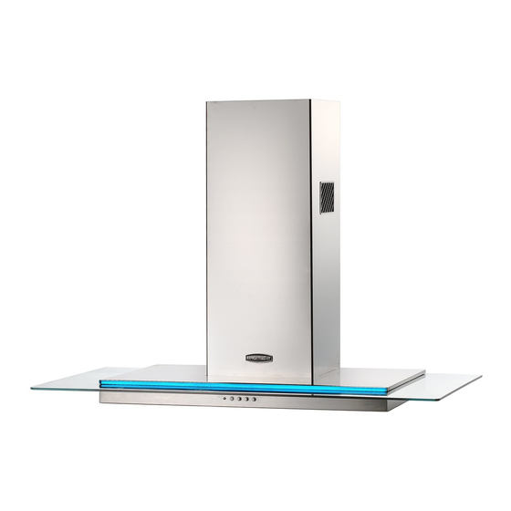
- Page 1 RMHDT90SS/ - RMHDT100SS/ - RMHDT110SS/ Instructions Manual www.rangemaster.co.uk...
-
Page 2: Table Of Contents
INDEX RECOMMENDATIONS AND SUGGESTIONS ........................3 CHARACTERISTICS ................................4 INSTALLATION..................................5 USE ......................................8 MAINTENANCE ..................................9... -
Page 3: Recommendations And Suggestions
RECOMMENDATIONS AND SUGGESTIONS The Instructions for Use apply to several versions of this appliance. Accord- ingly, you may find descriptions of individual features that do not apply to your specific appliance. INSTALLATION • The manufacturer will not be held liable for any damages resulting from in- correct or improper installation. -
Page 4: Characteristics
CHARACTERISTICS Dimensions Components Ref. Q.ty Product Components Hood Body, complete with: Controls, Light, Blower, Filters Telescopic Chimney comprising: Upper Section Lower Section Right Air Outlet Grill Left Air Outlet Grill Reducer Flange ø 150-120 mm Adapting ring ø 120-125 mm Hood Body Air Outlet Extension Piece consisting of two Half Shells 14.1... -
Page 5: Installation
INSTALLATION Wall drilling and bracket fixing Wall marking: • Draw a vertical line on the supporting wall up to the ceiling, or as high as practical, at the centre of the area in which the hood will be installed. • Draw a horizontal line at 650 mm above the hob. Place bracket 7.2.1 on the wall as shown about 1-2 mm from the ceiling or upper limit aligning the centre (notch) with the vertical reference line. - Page 6 Mounting the hood body • Before attaching the hood body, tighten the two screws Vr lo- cated on the hood body mounting points. • Hook the hood body onto the screws 12a. • Fully tighten the support screws 12a. • Adjust the screws Vr to level the hood body. Connections DUCTED VERSION AIR EXHAUST SYSTEM When installing the ducted version, connect the hood to the...
- Page 7 ELECTRICAL CONNECTION • Connect the hood to the mains through a two-pole switch hav- ing a contact gap of at least 3 mm. • Remove the grease filters (see paragraph Maintenance) being sure that the connector of the feeding cable is correctly inserted in the socket placed on the side of the fan.
-
Page 8: Use
Light Switches the lighting system on and off. Motor running led. Motor Switches the extractor motor on and off at low speed. Used to provide a continuous and silent air change in the presence of light cooking vapours. Speed Medium speed, suitable for most operating conditions given the optimum treated air flow/noise level ratio. -
Page 9: Maintenance
MAINTENANCE Grease filters CLEANING METAL SELF- SUPPORTING GREASE FILTERS • The filters must be cleaned every 2 months of operation, or more frequently for particularly heavy usage, and can be washed in a dishwasher. • Remove the filters one at a time by pushing them towards the back of the group and pulling down at the same time. - Page 12 AGA RANGEMASTER GROUP PLC 436001900_ver8...
Need help?
Do you have a question about the RMHDT90SS and is the answer not in the manual?
Questions and answers