Table of Contents
Advertisement
Advertisement
Table of Contents

Related Manuals for Para systems EN400


Summary of Contents for Para systems EN400
- Page 1 Enspire Series UPS User's Manual...
-
Page 2: Table Of Contents
Introduction Controls and Indicators Installation Operation Troubleshooting Replacing the Battery Obtaining Service Specifications Limited Product Warranty A1. Declaration of Conformity © Copyright 2006... -
Page 3: Introduction
SAVE THESE INSTRUCTIONS ! Please read this manual before installing your Enspire Series UPS, models EN400, EN600 as it provides important information that should be followed during installation and maintenance of the UPS and batteries allowing you to correctly set up your system for the maximum safety and performance. In- cluded is information on customer support and factory service if it is required. - Page 4 This symbol indicates "Direct Current Supply" This symbol indicates "Equipment Grounding Conductor" CAUTION! Connect the UPS to a two pole, three wire grounding AC wall outlet. The receptacle must be connected to the appropriate branch protection (circuit breaker or fuse). Connection to any other type of receptacle may result in a shock hazard and violate local electrical codes.
-
Page 5: Receiving Inspection
NOTICE: This equipment has been tested and found to comply with the limits for a Class B computing device in accordance with the specifications in Sub- part J of Part 15 of FCC Rules and the Class B limits for radio noise emissions from digital apparatus set out in the Radio Interference of the Canadian Depart- ment of Communications. -
Page 6: Life Support Policy
Life Support Policy As a general policy, we do not recommend the use of any of our products in life support applications where failure or malfunction of the product can be reason- ably expected to cause failure of the life support device or to significantly affect its safety or effectiveness. -
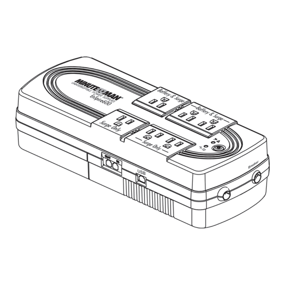
Page 7: Controls And Indicators
9. The RJ45 connector is for the USB communications port for UPS monitoring and control. Input Power Plug Model # Output Power Receptacles EN400 3-NEMA 5-15R Surge Only NEMA 5-15P W/6 ft cord 3-NEMA 5-15R Battery Backup & Surge EN600... -
Page 8: Installation
INSTALLATION PLACEMENT This UPS series is intended to be install in a temperature controlled environment that is free of conductive contaminants. Select a location which will provide good air circulation for the UPS at all times. Avoid locations near heating devices, water or excessive humidity, or where the UPS is exposed to direct sunlight. - Page 9 CONNECTING THE BATTERIES (QUALIFIED SERVICE PERSONNEL ONLY) Please read all of the WARNINGS and CAUTIONS before attempting to con- nect the batteries. 1. Remove the UPS from the shipping box and set on the floor or a bench top. 2. Place the UPS receptacle side down. 3.
- Page 10 CONNECTING YOUR EQUIPMENT Plug the critical equipment into the Battery Backup & Surge output receptacles on the UPS. Plug the non-critical equipment into the Surge Only output recep- tacles on the UPS. Do not use extension cords, adapter plugs or surge strips on the output of the UPS.
-
Page 11: Operation
SYSTEM OVERVIEW This UPS protects computers, internetworking, security, and telecommunica- tions equipment from blackouts, brownouts, overvoltages, and surges. During normal AC operation, the UPS will quietly and confidently protect your system from power anomalies. The UPS will charge the batteries with the UPS in the on or off position when the UPS is plugged into the wall outlet and there is an acceptable AC voltage present (100 - 140VAC). - Page 12 RJ-45 USB COMMUNICATIONS PORT The USB communications protocol is HID. The HID USB driver comes stan- dard in the Windows OS. Simply plug the USB cable into the UPS and the computer then follow the prompts on the screen. POWER MONITORING SOFTWARE The UPS comes with power monitoring software.
-
Page 13: Troubleshooting
What To Do Possible Cause Symptom On/Off/ button not pressed Press and release the On/Off UPS will not turn on button to start UPS Reset circuit breaker by UPS operates in Input AC circuit breaker is tripped pressing the plunger back in. battery mode only, even though there If the AC circuit breaker trips... -
Page 14: Replacing The Battery
REPLACING THE BATTERY (QUALIFIED SERVICE PERSONNEL ONLY) Please read all of the WARNINGS and CAUTIONS before attempting to service the batteries. This UPS contains potentially hazardous voltages. Do not at- WARNING! tempt to disassemble the UPS beyond the battery replacement procedure. -
Page 15: Battery Replacement Procedure
CAUTION: Replace batteries with the same number and type as originally installed in the UPS. These batteries have pressure operated vents. These UPSs contain sealed non-spillable maintenance-free lead acid batteries. EN400 Model # EN600 Battery 1-12V4.5Ah 1-12V5.0Ah Qty/Rating Ritar Power... - Page 16 18. Re-install the battery compartment retaining screws. 19. Properly dispose of the old batteries at an appropriate recycling facility or return them to the supplier in the packing material for the new batteries. 20. The UPS is now ready for normal operation. FIG.
-
Page 17: Obtaining Service
IF THE UPS REQUIRES SERVICE 1. Use the TROUBLESHOOTING section to eliminate obvious causes. 2. Verify there are no circuit breakers tripped. A tripped circuit breaker is the most common problem. 3. Call your dealer for assistance. If you cannot reach your dealer, or if they cannot resolve the problem call or fax the Technical Support department at the following numbers;... -
Page 18: Specifications
SYSTEM SPECIFICATIONS Model Number EN600 EN400 600VA / 300W 400VA / 200W Maximum Power Capacity INPUT Number of Phase Single (1∅ 2W +G) Nominal Voltage 120VAC Acceptable Input voltage 0 - 160VAC 100 - 140VAC Voltage Range Frequency Limits 50 or 60 Hz, +/-5Hz, autosensing... -
Page 19: Limited Product Warranty
Para Systems, Inc. (Para Systems) warrants this equipment, when properly applied and operated within specified conditions, against faulty materials (excluding the batteries) or workmanship for a period of three years from the date of purchase. Para Systems Inc. (Para Systems) warrants the batteries for a period of two years from the date of purchase. -
Page 20: A1. Declaration Of Conformity
Manufacturer’s Address: 1455 LeMay Drive Carrollton, Texas 75007 USA Type of Equipment: Uninterruptible Power Supplies (UPS) Model No: EN400, EN600 Year of Manufacture: Beginning November 1, 2006 I hereby declare that the equipment specified above conforms to the above Directive(s). - Page 21 Notes:...
- Page 23 Para Systems, Inc. 1455 Lemay Dr. Carrollton, TX 75007 Phone: 1-972-446-7363 Fax: 1-972-446-9011 Internet: minutemanups.com UPS Sizing: sizemyups.com PN - 34000293 R1...
Need help?
Do you have a question about the EN400 and is the answer not in the manual?
Questions and answers