Table of Contents
Advertisement
Quick Links
Advertisement
Table of Contents

Related Manuals for Lantronix C 7/01


Summary of Contents for Lantronix C 7/01
- Page 1 CoBox-FL-IAP User Guide Rev. C 7/01...
-
Page 2: Table Of Contents
Contents Chapter 1: Introduction The IAP Family of Device Servers............1-1 Key Features ..................1-2 Network Protocols ................. 1-3 Packing Algorithms ..............1-3 Ethernet (MAC) Address............1-3 Internet Protocol (IP) Address..........1-3 Port Numbers................1-3 Chapter 2: Installation Product Description ................2-1 Network Interface.............. - Page 3 Appendix B: Troubleshooting Monitor Mode..................B-1 Entering Monitor Mode Via the Serial Port ......B-1 Entering Monitor Mode Via the Network Port......B-1 Monitor Mode Commands............B-2 Appendix C: Updating Firmware Downloading Firmware .................C-1 Downloading Via the APS Configuration Utility........C-1 Downloading Via TFTP ................C-3 Downloading Via the Serial Port............C-4 Appendix D: Technical Specifications CoBox-FL-IAP ..................
-
Page 4: The Iap Family Of Device Servers
1: Introduction The IAP Family of Device Servers The Lantronix Industrial Automation Platform (IAP) family of Device Servers allows a single network and protocol to connect multiple serial devices from many vendors. IAP provides the automation industry with a network-enabling solution using TCP/IP and standard Ethernet networks that is vendor-independent. -
Page 5: Key Features
IT layer. The IAP Device Servers feature installable industrial communication protocols. Lantronix’s Automation Protocols Suite (APS) includes protocols such as DF1 (Rockwell Automation) and Modbus (Schneider Electric). Where the Standard Tunneling protocol is limited to exclusive, device-to-device connections, the industrial protocols offer connections to other devices simultaneously. -
Page 6: Network Protocols
The Ethernet address is also referred to as the hardware address or the MAC address. The first three bytes of the Ethernet Address are fixed (e.g., 00-20-4A), identifying the unit as a Lantronix product. The fourth, fifth, and sixth bytes are unique numbers assigned to each Device Server. -
Page 7: Product Description
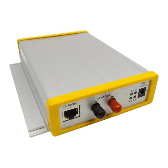
2: Installation This chapter describes the CoBox-FL-IAP and shows how to install it on a basic network. Product Description Network Interface The CoBox-FL-IAP’s network panel contains a 9-30VDC or 9-25VAC power plug, four LEDs, an ST-Fiber (10BASE-FL) Ethernet port, and an RJ45 (10BASE-T) Ethernet port. Both Ethernet ports support 10 Mbps and are auto detecting. -
Page 8: Serial Interface
Product Description Installation Serial Interface The CoBox-FL-IAP’s serial panel contains two serial ports and three LEDs. Port (Channel) 1 is a female DB25 (DCE) that supports RS-232, RS-485, and RS-422 serial standards (firmware selectable) up to 115.2 Kbps. Port (Channel) 2 is a male DB9 (DTE) that supports RS-232 only. -
Page 9: Installing The Cobox-Fl-Iap
Installation Installing the CoBox-FL-IAP Installing the CoBox-FL-IAP The following connection diagram shows a typical CoBox-FL-IAP used to attach serial devices to a network. Figure 2-3: CoBox-FL-IAP Connected to Serial Device and Network Serial Device 2 Serial Device 1 10BASE-T 10BASE-FL Ethernet Ethernet To install the CoBox-FL-IAP, complete the following steps in order. -
Page 10: Leds
Installing the CoBox-FL-IAP Installation LEDs Network LEDs The following table explains the function of the four network LEDs: Table 2-1: CoBox-FL-IAP Network LEDs Function GL (Good Link) Lights solid green to indicate network port is connected to the network. Tx (Network Transmit) Blinks yellow to indicate network packets are transmitting. Rx (Network Receive) Blinks yellow to indicate network packets are receiving. -
Page 11: Assigning The Ip Address
3: Getting Started This chapter covers the required steps to get the Device Server on-line and working. Consider the following points before logging into and configuring the Device Server: The Device Server’s IP address must be configured before a network connection is available. -
Page 12: Auto Ip
Assigning the IP Address Getting Started A DHCP-assigned IP address does not appear in the Device Server’s configuration screen (Setup Menu). You can, however, determine your Device Server’s DHCP-assigned IP address in Monitor Mode. When you enter Monitor Mode from the serial port with network connection enabled and issue the NC (Network Connection) command., you will see the Device Server’s IP configuration. -
Page 13: Aps Configuration Utility
Getting Started Assigning the IP Address AutoIP is not intended to replace DHCP. The Device Server will continue to look for a DHCP server on the network. If it finds a DHCP server, the Device Server will switch to the DHCP server-provided address and reboot. Note: If a DHCP server is found, but it denies the request for an IP address, the Device Server does not attach to the network, but waits and retries. - Page 14 Assigning the IP Address Getting Started Click the Assign IP icon. The Assign IP Address window displays. Figure 3-2: Assign IP Address Window. In the Enter IP Address to assign field, type the IP address of the Device Server (XXX.XXX.XXX.XXX format). In the Enter the Hardware or Ethernet Address field, type the Ethernet address (MAC address) listed on the Device Server label.
- Page 15 Getting Started Assigning the IP Address Note: If you do not receive Reply received messages, make sure the Device Server is properly attached to the network and that the IP address assigned is valid for the particular network segment you are working with.
- Page 16 Assigning the IP Address Getting Started Load the Protocol (Firmware) Click the Load icon. The Load Firmware window displays. Click Select FW File. A list of firmware files displays Figure 3-4: Firmware Files. Select the desired protocol and click Open. The selected file displays in the FW File field.
-
Page 17: Arp
Getting Started Assigning the IP Address ARP can be used from a Windows or Unix host to assign a temporary IP address to the Device Server. The server sets its IP address from a directed ARP packet and uses it until it is rebooted. -
Page 18: Direct Serial Connection
Configuring the Device Server Getting Started Direct Serial Connection Connect a console terminal or PC running a terminal emulation program to the Device Server’s first serial port (CH 1). The default serial port settings are 9600 baud, 8 bits, no parity, 1 stop bit, no flow control. To enter Setup (configuration) Mode, cycle the Device Server’s power (power off and back on). -
Page 19: Comm Port Redirector
4: Using the Device Server Comm Port Redirector The Lantronix Comm Port Redirector application allows PCs to share modems and other serial devices connected to a Device Server using Windows-based applications. The Comm Port Redirector intercepts communications to specified communication ports and sends them over an IP network connection to the Device Server’s serial port. -
Page 20: Problem Report Procedure
Look on the APS CD that was included in your package for additional documentation and support information Look on the Lantronix Web site for technical FAQs and documentation updates. For information pertaining to your system’s configuration, refer to your system’s documentation or technical support. -
Page 21: Full Contact Information
Contact Information Full Contact Information Corporate Offices 15353 Barranca Parkway Irvine, CA 92618, USA Phone: (949) 453-3990 Fax: (949) 453-3995 World Wide Web: www.lantronix.com Sales Offices The Americas 15353 Barranca Parkway Irvine, CA 92618, USA Phone: (949) 450-7227 Fax: (949) 450-7231 E-mail: sales@lantronix.com... - Page 22 Contact Information Full Contact Information United Kingdom and Ireland Phone: +44 (0) 118 945 1555 Fax: +44 (0) 118 945 1663 E-mail: eu_sales@lantronix.com International Sales Phone: (949) 450-7227 Fax: (949) 450-7231 E-mail: intsales@lantronix.com Technical Support Contact the Industrial Automation Distributor assigned to sell and support in your region.
-
Page 23: Monitor Mode
Establish a Telnet session to the configuration port (9999). Immediately after the following message displays, type M (upper case). Figure B-3: Entering Monitor Mode Via the Network *** Lantronix Universal Device Server *** Serial Number 1400280 MAC address 00:20:4A:14:01:18 Software Version 04.0b7 (000428) Press Enter to go into Setup Mode A 0>... -
Page 24: Monitor Mode Commands
Monitor Mode Troubleshooting Monitor Mode Commands The following commands are available in Monitor Mode. Many commands have an IP address as an optional parameter (xxx.xxx.xxx.xxx). If the IP address is given, the command is applied to another Device Server with that IP address. If no IP address is given, the command is executed locally. - Page 25 Troubleshooting Monitor Mode Entering any of the commands listed above will generate one of the following command response codes: Table B-2: Command Response Codes Response Meaning 0> OK; no error 1> No answer from remote device 2> Cannot reach remote device or no answer 8>...
-
Page 26: Downloading Firmware
Current firmware files are available on the APS CD. Firmware updates and release notes for Device Servers can be downloaded directly from Lantronix in one of the following ways: via the Lantronix Web site (www.lantronix.com), or using anonymous FTP through the Internet (ftp.lantronix.com). - Page 27 Downloading Via the APS Configuration Utility Updating Firmware Click the Load Firmware icon . The Load Firmware window displays. Figure C-2: Load Firmware Window Type the Device Server’s assigned IP address in the IP Address field. Click the Select FW File button. The files in your Firmware folder display. (If the files are stored elsewhere, browse until you find them.) Figure C-4: Firmware Files Select the file to download and click the Open button.
-
Page 28: Downloading Via Tftp
Updating Firmware Downloading Via TFTP Downloading Via TFTP To download new firmware from a computer: Use a TFTP client to send a binary file to the Device Server (CBX*.ROM to upgrade the Device Server’s internal operational code and CBXW*.COB to upgrade its internal Web interface). -
Page 29: Downloading Via The Serial Port
Downloading Via the Serial Port Updating Firmware Downloading Via the Serial Port Note: This procedure takes about 10 minutes. Do not switch off the power supply during the update. A loss of power while reprogramming will result in a corrupt program image and a nonfunctional Device Server. To download firmware from a computer via the Device Server’s serial port: Enter Monitor Mode. -
Page 30: Cobox-Fl-Iap
D: Technical Specifications CoBox-FL-IAP The following table lists technical information about the CoBox-FL-IAP Device Server. Table D-1: CoBox-FL-IAP Technical Specifications ARP, UDP, TCP, Telnet, ICMP, SNMP, DHCP, TFTP, HTTP, BootP, Protocols Supported and ECHO 10BASE-T or 10BASE-FL Network Interface DB25 RS-232/RS-422/RS-485 serial port with DCE configuration Serial Interface DB9 RS233 serial port with DTE configuration Serial speed ranging from 300 bps - 115.2 Kbps... - Page 31 CoBox-FL-IAP Technical Specifications 9-30VDC or 9-25VAC (External adapter included) Power Requirements Power Consumption: 3 Watts Flash: 512K Memory RAM: 128K NVRAM: 2K Operating Temperature: 5to 50C (41 to 122F) Environmental Storage Temperature: -40 to 66C (-40 to 151F) 6.5 x 4.46 x 1.39 in (16.51 x 11.34 x 3.55 cm) Physical Dimensions 1.10 lbs (.48 kg) Weight...
-
Page 32: Network Portion
E: IP Addressing Each TCP/IP node on a network host has a unique IP address. This address provides the information needed to forward packets on the local network and across multiple networks if necessary. IP addresses are specified as x.x.x.x, where each x is a number from 1 to 254, for example, 192.0.1.99. -
Page 33: Subnet Portion
Subnet Portion IP Addressing Consider the IP address 36.1.3.4. This address is a Class A address; therefore, the network portion of the address is 36.0.0.0, and the host portion is 1.3.4. Subnet Portion The subnet portion of the IP address represents which subnetwork the address is from. Subnetworks are formed when an IP network is broken down into smaller networks using a subnet mask. -
Page 34: Ip Subnet Mask
IP Addressing IP Subnet Mask IP Subnet Mask A subnet mask divides IP addresses differently from the standards defined by the classes A, B, and C. A subnet mask defines the number of bits to be taken from the IP address as the network or host sections. -
Page 35: Private Ip Networks And The Internet
Private IP Networks and the Internet IP Addressing Private IP Networks and the Internet If your network is not and will not be connected to the Internet, you may use any IP address. If your network is connected or will be connected to the Internet, or if you intend to operate the Device Server on an intranet, you should use one of the reserved subnetworks. -
Page 36: Ethernet Connectors
F: Pinouts Ethernet Connectors The CoBox-FL-IAP contains a 10BASE-T ethernet connector and a 10BASE-FL ethernet connector. Note: Do not attempt to connect both Ethernet ports simultaneously.If one is used, the other is disabled. 10BASE-T The CoBox-FL-IAP supports 10 Mbit Ethernet through an RJ45 connector. Figure F-1: RJ45 Ethernet Connector 1 - Tx+ 2 - Tx-... -
Page 37: Serial Connectors
Serial Connectors Pinouts Serial Connectors The CoBox-FL-IAP’s female DB25 connector provides an RS-232C, RS-485, or RS-422 DCE serial interface. The default serial port settings are 9600 baud, 8 bits, no parity, and 1 stop bit. Figure F-3: DB25 Serial Connector (DCE) TX+ (out)** TX (in) TX- (out)**... -
Page 38: Warranty Statement
No services are handled at the customer’s site under this warranty. Lantronix warrants software for a period of sixty (60) days from the date of shipment that each soft- ware package supplied shall be free from defects and shall operate according to Lantronix specifica- tions. -
Page 39: Declaration Of Conformity
Class A limits of the FCC Radio Fre- quency Devices Rules (FCC Part 15, Subpart B), revised as of October 1993. Manufacturer’s Contact: Director of Quality Assurance, Lantronix, 15353 Barranca Parkway Irvine, CA 92618 USA General Tel: 949/453-3990... - Page 40 Microsoft Corp. Netscape is a trademark of Netscape Communications Corporation. Copyright 2001, Lantronix. All rights reserved. No part of the contents of this book may be transmitted or reproduced in any form or by any means without the written permission of Lantronix.
Need help?
Do you have a question about the C 7/01 and is the answer not in the manual?
Questions and answers