Table of Contents
Advertisement
Quick Links
Advertisement
Table of Contents

Related Manuals for Lantronix CoBox-FL


Summary of Contents for Lantronix CoBox-FL
-
Page 1: User Guide
CoBox-FL/CoBox-FL-IAP User Guide Part Number 900-285 Revision E 8/03... -
Page 2: Copyright And Trademark
Copyright and Trademark © 2003, Lantronix. All rights reserved. No part of the contents of this book may be transmitted or reproduced in any form or by any means without the written permission of Lantronix. Printed in the United States of America. -
Page 3: Disclaimer And Revisions
Changes or modifications to this device not explicitly approved by Lantronix will void the user's authority to operate this device. -
Page 4: Declaration Of Conformity
Declaration of Conformity (according to ISO/IEC Guide 22 and BS 7514) Manufacturer’s Name & Address: Lantronix, 15353 Barranca Parkway, Irvine, CA 92618 USA Declares that the following product: Product Name Model: CoBox-FL/CoBox-FL-IAP Device Server Conforms to the following standards or other normative documents:... - Page 5 Lantronix, freight prepaid. Upon verification of warranty, Lantronix will -- at its option -- repair or replace the product and return it to the customer freight prepaid. No services are handled at the customer's site under this warranty. This warranty is voided if the customer uses the product in an unauthorized or improper way, or in an environment for which it was not designed.
-
Page 6: Sales Offices
Sales Offices The Americas 15353 Barranca Parkway Irvine, CA 92618, USA Phone: (949) 450-7227 Fax: (949) 450-7231 sales@lantronix.com France 2 Rue Hélène Boucher 78280 Guyancourt France Tel: +33 1 39 30 41 74 Fax: +33 1 39 30 41 73 europesud@lantronix.com... -
Page 7: Table Of Contents
Contents Table of Contents 1. Introduction........................1-1 1.1 CoBox-FL ......................1-1 1.2 CoBox-FL-IAP Device Server................1-2 1.2.1 Industrial Automation Protocols ............1-3 1.3 Network Protocols ....................1-4 1.3.1 Packing Algorithm................1-4 1.3.2 IP Address................... 1-4 1.3.3 Port Number..................1-4 1.4 Serial Interface....................1-5 1.4.1 Channel 1 .................... - Page 8 3.6.8 DisConnMode ...................3-20 3.6.9 Flush Mode (Buffer Flushing)............3-21 3.6.10 Pack Control ..................3-22 3.6.11 DisConnTime (Inactivity Timeout)..........3-23 3.6.12 Send Characters................3-23 3.6.13 Telnet Terminal Type..............3-23 3.6.14 Channel (Port) Password ..............3-23 3.7 Expert Settings ....................3-24 3.7.1 TCP Keepalive time in s..............3-24 CoBox-FL User Guide...
- Page 9 8.2 Configuring Multiple Devices ................8-3 8.2.1 Acquiring a Valid Setup Record ............8-3 8.2.2 Sending a Setup Record ..............8-4 8.2.3 The Intel Hex Format................8-5 8.2.4 Calculating the Checksum ..............8-6 8.2.5 Calculating the Two’s Complement ........... 8-6 CoBox-FL User Guide...
- Page 10 10. IP Addresses........................10-1 10.1 Class A Network .....................10-1 10.2 Class B Network....................10-1 10.3 Class C Network....................10-1 10.4 Network Address.....................10-2 10.5 Broadcast Address ...................10-2 10.6 IP Netmask ......................10-2 10.7 Private IP Networks and the Internet...............10-3 10.8 Network RFCs....................10-3 11. Glossary.........................11-1 CoBox-FL User Guide...
- Page 11 List of Figures Figure 1 – CoBox-FL-IAP ..................... 1-2 Figure 2 - RJ-45 Connector....................1-7 Figure 3 – CoBox-FL Connected to Serial Device and Network .......... 2-2 Figure 4 – CD Main Window ....................2-5 Figure 5 - DeviceInstaller Window..................2-6 Figure 6 - Assign IP Address Window ..................
- Page 12 Contents List of Tables Table 1 - Ethernet Interface Signals ..................1-7 Table 2 - CoBox-FL LED Functions..................1-9 Table 3 - Technical Specs.....................1-12 Table 4 - Standard IP Network Netmasks ................3-13 Table 5 - Netmask Examples....................3-13 Table 6 - Interface Mode Options ..................3-15 Table 7 - Common Interface Mode Settings ................3-16...
- Page 13 Contents Table 38 - Disconnect Mode Options ..................9-5 Table 39 - Flush Mode Options ..................... 9-7 Table 40 - Interface Mode Options ..................9-13 Table 41 - Pack Control Options ..................9-14 CoBox-FL User Guide...
-
Page 15: Introduction
Device Server and the CoBox-FL-IAP Device Server with Industrial Automation Protocols. Most of the material in this manual applies to all of the CoBox-FL products. However, in some cases there will be some features that apply to only one product. In those cases, a note will explain the variation. -
Page 16: Cobox-Fl-Iap Device Server
1.2 CoBox-FL-IAP Device Server Note: This section is for the CoBox-FL-IAP only. The Lantronix Industrial Automation Platform (IAP) family of Device Servers allows a single network and protocol to connect multiple serial devices from many vendors. IAP provides the automation industry with a network-enabling solution using TCP/IP and standard Ethernet networks that is vendor-independent. -
Page 17: Industrial Automation Protocols
CD or our web site. Protocol firmware files are also contained on the CD and new versions are available from the Lantronix web site. You can set up the unit using the serial port, or remotely over Ethernet using Telnet or a web browser. -
Page 18: Network Protocols
IP address/port number combinations must be different. In the CoBox-FL, a port number can be configured on the channel (port). The CoBox-FL uses this port number for outgoing messages and incoming connections, or UDP datagrams, which are addressed to its port number. -
Page 19: Serial Interface
Introduction 1.4 Serial Interface The CoBox-FL has two serial ports. CH 1 uses a DB-25F (DCE) connector and supports RS- 232, RS-422/485. CH 2 uses a DB-9 connector and supports RS-232 only. It supports 10Mb/s Ethernet through the RJ-45 (10BASE-T) connector or the ST-Fiber (10BASE-FL). It can be configured via HTTP, SNMP, DHCP or Telnet. -
Page 20: Channel 2
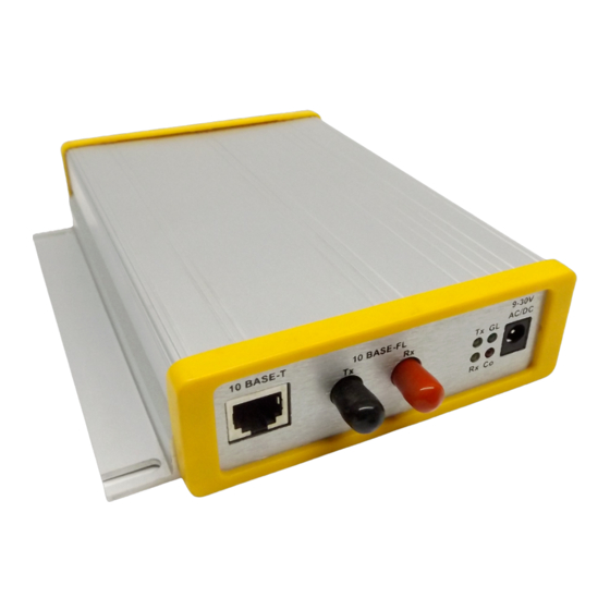
RXA(in) DCDA (in) 1.5 RJ-45 Ethernet Interface The CoBox-FL’s back panel contains a 9-30V AC/DC power plug, four LEDs, an ST-Fiber (10BASE-FL) Ethernet port, and an RJ-45 (10BASE-T) Ethernet port. Both Ethernet ports support 10 Mbps and are auto detecting. -
Page 21: Ethernet Connector
Differential Ethernet Receive Data + Differential Ethernet Receive Data - 1.7 ST-Fiber Ethernet Connectors The CoBox-FL also supports 10Mbit Ethernet through an ST-Fiber Ethernet connector. Note: Do not attempt to connect both Ethernet ports simultaneously. If one is used, the other is disabled. -
Page 22: Serial Interface Cable
Introduction .8 Serial In terface Cable The CoBox-FL can be conn ected to a seria l or Ethernet device for setup and configuration. he serial device can be -232 or RS-485/422. The following diagram shows a typica nterface cable for the RS 32 Serial interface. The UDS-M-SBC is an optional male... -
Page 23: Serial Leds
Blink patterns indicate which fault condition exists. The following table explains the functions of the three serial LEDs. LEDs Table 2 - CoBox-FL LED Functions Meaning GREEN Lights solid green to indica te that Channel 1 does not have a... -
Page 24: Dimensions
DeviceInstaller is a powerful software utility for configuring device servers from a network connection. For more information, see Using DeviceInstaller on page 3-2. Lantronix DeviceComm Manager is a Windows based COM port redirector software utility. Its function is to redirect customer application data destined for a local serial (COM) port to the PC’s network port. -
Page 25: Power Requirements
Introduction 1.14 Power Requirements The CoBox-FL is shipped with a 12VDC, 0.8A, 100-240VAC, 50-60Hz power supply, but any power supply between 9 VAC/DC and 30V AC/DC can be used. 9-30V AC/DC Power CoBox-FL User Guide 1-11... -
Page 26: Technical Specifications
CPU, Memory AMD 188ES CPU, 20MHz clo ck, 128kByte RAM Flash, EPROM 512kByte Flash PROM Installable Serial Standard Tunnel (CoBox-F L, and CoBox-FL-IAP), Modbus (CoBox- Protocols FL-IAP), DF1 (CoBox-FL-IAP) Serial Interface DB-25F, RS-232C or RS-4 22/485 (DCE pinout) DB-9M, RS-232C (DTE pin... -
Page 27: Getting Started
This section describes all the procedures for configuring your unit. For a short version, see the Quick Start Guide. Go to the Lantronix web site for the latest firmware and release notes. CoBox-FL comes with Standard Tunnel Protocol and the CoBox-FL-IAP comes with the IAP Standard Tunnel Protocol. -
Page 28: Port Number
9999 is reserved for access to the unit's Setup (configuration) Mode window. 2.2 Physically Connecting the Unit The following diagram shows a typical hardware configuration for the CoBox-FL. Use one of the cables described in Serial Interface Cable on page 1-8 to connect a PC COM port to the CoBox-FL. -
Page 29: Methods Of Assigning The Ip Address
Note: In most installations, a fixed IP address is desirable. The systems administrator generally provides the IP address. Obtain the following information before starting to set up your unit: IP Address: ___ ___ ___ ___ Subnet Mask: ___ ___ ___ ___ Gateway: ___ ___ ___ ___ CoBox-FL User Guide... -
Page 30: Dhcp
Provided a DHCP server exists on the network, it will assign the unit an IP address, gateway address, and subnet mask when the unit boots up. The CoBox-FL has acquired an IP address if the red LED stops flashing and the green LED is on continuously. -
Page 31: Deviceinstaller
Enter your CD drive letter, colon, backslash, deviceinstaller.exe (e.g., E:\deviceinstaller.exe). Figure 4 – CD Main Window 2. Click the Device Installer button. The installation wizard window displays. 3. Respond to the installation wizard prompts. (When prompted to select an installation type, select Typical.) CoBox-FL User Guide... -
Page 32: Assign Ip Address And Network Class
Assign IP Address window displa Figure 6 - Assign IP Address Window 2. In the Enter the Hardware or Ethernet Address field, enter the Ethernet address (MAC address), which is listed on the label on the side of the unit. CoBox-FL User Guide... -
Page 33: Test The Ip Address
IP address assigned is valid for the particular network segment you are working with. If you are not sure, check with your systems administrator. 3. Click the Back button to retu rn to the Device Installer window. CoBox-FL User Guide... -
Page 34: Add The Unit To The Manage List
Getting Started 2.4.4 Add the Unit to the Manage List Now add the unit to the list of similar Lantronix devices on the network so that you can manage and configure it. 1. Click the Search the network for devices icon. -
Page 35: Figure 9 - Devices In A Group
The hardware address and firmware release number for the unit display. ure 9 - Devices in a Group you can manage (configure) the unit so that it works with the serial device on the netw ork. CoBox-FL User Guide... -
Page 36: Opening A Configuration Window
Telnet session. • To configure the unit via a Web browser, click the Web Configuration icon The Lantronix Web-Manager window displays in your browser. For Web Configuration, see Web Manager Page on page 3-4. • To configure the unit via a Telnet session, click the Telnet to Device icon The Setup Mode window displays. -
Page 37: Arp And Telnet
Note: The IP address you just set is temporary and will revert to the defau value when th unit 's power is reset unless you log into the unit and store the changes per anently. Refe r to chapter on configuration for instructions on permanently configuring t he IP address. CoBox-FL User Guide 2-11... -
Page 38: Serial Port Login
3. At this point, the screen display is the same as when you use a Telnet connectio n. To continue with a serial port login, go to Using a Telnet Connection on page 3-1 2-12 CoBox-FL User Guide... -
Page 39: Configuring The Unit
Open your JAVA enabled web browser and enter the IP address. The Lantronix Web Manager page will display. Go to Web Manager Page for a summary of the menu selections. Note: The CoBox-FL-IAP may not have a web page or may use a different format web page. CoBox-FL User Guide... -
Page 40: Using Deviceinstaller
IP address (see Methods of Assigning the IP Address), you can log into it usin g a standard Web browser that is Java enabled. Type the unit's IP address into the Web browser's URL (Address/Location) field. CoBox-FL User Guide... - Page 41 Configure 6. For Telnet configuration, click the Telnet to Device icon. A small Telnet to Device window appears, showing the IP Address and the Port address. The main Lantronix Universal Device Serve r window opens. Go to Using a Telnet Connection on page 3-10 for a summary of the menu selections.
-
Page 42: Web Manager Page
Configure 3.3 Web Manager Page Note: The CoBox-FL-IAP may not have a web page or may use a different format web page. You can start a web browser for configuration by opening your JAVA enabled web browser and entering the IP address or by clicking the Web Configuration button on the Device Management window. -
Page 43: Unit Configuration
Click the Unit Configuration button to display the following dialog box. This page contain the Server Configuration and the Port Configuration settings. These are static settings read from the device. Note: The following screen shots represent the web page shown wh en the device is loaded with cbxw300.cob firmware. CoBox-FL User Guide... -
Page 44: Server Properties
Mode via a Telnet connection to port 9999. The password is limited to 4 characters. (An enhanced password setting of 16 characters is available under Security Settings on the Tel Setup Mode window.) Note: No password is required to access the Setup Mode window via a serial connection. CoBox-FL User Guide... -
Page 45: Port Properties
Response: Nothing (quiet), Character response Startup: No active startup, with any character, with active DTR (Inactive), with CR (0x0D) only, Manual Connection, Autostart, Modem Mode Remote IP Address: (user selectable) Remote Port: (user selectable) Local Port: 10001 (default 10001, user selectable) CoBox-FL User Guide... - Page 46 Idle Time: Force transmit 12 ms, Force transmit 52 ms, Force Transmit 250 ms, Force Transmit 5000 ms Trailing Characters: None, One, Two Send Immediate After Sendchars: Enable, Disable Send Define2-Byte Sequence: Enable, Disable Send Character 01: (User Selectable) Send Character 02: (User Selectable) CoBox-FL User Guide...
-
Page 47: Technical Support
The ontact Us button w ill link u to the Contact Information page. .3.5 Update Se ttings lick the Update Se ttings button to send all changed settings to the device. CoBox-FL User Guide... -
Page 48: Configuring Via The Setup Mode Window
9999 Note: Be sure to include a space between the IP address and 9999. 2. Click OK. 3. The Lantronix Universal Device Server window displays. *** Lantronix Universal Device Server *** Serial Number 7218033 MAC address 00:20:4A:72:46:71 Software version 04.5 (011025) -
Page 49: Figure 13 - Setup Mode Window
:0 Server configuratio 1 Channel 1 configuration 5 Expe rt settings (not IAP firmware) 6 Secu rity 7 Factory defaults 8 Exit without save 9 Save and exit Your choice ? Figure 13 - Setup Mode Window CoBox-FL User Guide 3-11... -
Page 50: Using The Serial Port
LAN segments. The gateway address should be the IP address of the router connected to the same LAN segment as the unit. The gateway addr ess must be within the local network. 3-12 CoBox-FL User Guide... -
Page 51: Netmask: Number Of Bits For Host Part
Table 4 - Standard IP Ne twork Netmasks Network Class Host Bits Netm sk 255.0.0.0 255.255.0.0 255.2 5.255.0 Table 5 - Netmask Examples Netmask Host Bits 255.255.255.252 255.255.255.248 255.255.255.240 255.255.255.224 255.255.255.192 255.255.255.128 255.255.255.0 255.255.254.0 255.255.252.0 255.255.248.0 255.128.0.0 255.0.0.0 CoBox-FL User Guide 3-13... -
Page 52: Change Telnet Configuration Password
YY is what you chose for the last octet of the IP address. If the IP address you specify 0.0.0.12, then the DHCP name will be LTX12. This method will only work with 2 digit numbers (0-99). 3-14 CoBox-FL User Guide... -
Page 53: Channel 1 Configuration (Serial Port Parameters)
No Parity Even Parity Odd Parity 1 Stop bit 2 Stop bit (1) The CoBox-FL requires you to choose the correct setting in the IF mode, and to also set the front-panel switch for selection of RS-232/RS-485. CoBox-FL User Guide 3-15... -
Page 54: Flow
0100 1111 RS-422, 8-bit, Odd Parity, 1 stop bit 0101 1101 (1) The CoBox-FL requires you to choose the correct setting in the IF mode. 3.6.3 Flow Flow control sets the local handshake method for stopping serial input/output. Table 8 - Flow Control Options... -
Page 55: Connect Mode
IP address already configured in the unit is 129.1.2.3, then an example command string would be C3/7. (This would connect to 129.1.2.3 and port 7.) You may also use a different ending for the connection string. For example, C50.1/23 would connect you to 129.1.50.1 and port 23. CoBox-FL User Guide 3-17... -
Page 56: Table 10 - Manual Connection Address Example
+ is sent. • The unit acknowledges with an OK to indicate that it is in command mode. • Enter ATH and press Enter. It is echoed if echo is enabled. ATH is acknowledge by another OK. 3-18 CoBox-FL User Guide... -
Page 57: Table 11 - Modem Mode Commands
Note: These AT commands are only recognized as single commands like ATE0 or ATV1; compound commands such as ATE0V1 are not recognized. All other AT commands with Modem Mode set to full verbose acknowledge with an OK, but no action is taken. CoBox-FL User Guide 3-19... -
Page 58: Remote Ip Address
Disconnect with EOT to function properly. Ctrl D will only be detected going from the serial port to the network. 6. When DTR on the CoBox/UDS product transitions from a high state to a low state, then the network connection to or from the serial port will drop. 3-20 CoBox-FL User Guide... -
Page 59: Flush Mode (Buffer Flushing)
Clear with a connection that is initiated from the UDS to the network Clear with a connection initiated from the network to the UDS Clear when the network connection to or from the UDS is disconnected Alternate Packing Algorithm (Pack Control) Enable CoBox-FL User Guide 3-21... -
Page 60: Pack Control
Trailing Characters: In some applications, CRC, Checksum, or other trailing characters follow the end-of-sequence character; this option helps to adapt frame transmission to the frame boundary. 3-22 CoBox-FL User Guide... -
Page 61: Disconntime (Inactivity Timeout)
This param eter appears only if the channel ( rt) p assword option is enabled in Disconnect Mode (see D onnMode on page 3- 20). If set, you can set a password on the serial port. CoBox-FL User Guide 3-23... -
Page 62: Expert Settings
Note: You can change these settings via Telnet or serial connections only, not on the Web- Manager. Note: The Expert Settings option does not appear with CoBox-FL-IAP. These parameters should only be changed if you are an expert and definitely know the consequences the changes might have. -
Page 63: Disable Telnet Setup
Port 77FE is a setting that allows DeviceInstaller, Web Pages, and custom programs to figure the unit remotely. You may wish to disable this capability for security purposes. more information ab out remote configuration, see the Lantronix Embedded Integration Kit user guide on the Lantronix Web site www.lantronix.com. -
Page 64: Exit Configuration Mode
DeviceInstaller main window. In the Configuration File field, click the Open File button to select a filename for the configuration file. Click the Get button and the file information is read from the devic e and saved in the selected file. 3-26 CoBox-FL User Guide... -
Page 65: Set Configuration
The Device IP Address is shown in the first field. This is the device selected in the DeviceInstaller main window. In the Configuration File field, click the Open File button to select a configuration file. Click the Set button and the file information is read and stored in the device. CoBox-FL User Guide 3-27... -
Page 67: Updating Protocol (Firmware)
Web interface (*.COB) via TFTP or DeviceInstaller. The firmware files are located on the software CD in the firmware folder. Here is a list of typical names for those files. Check the Lantronix web site for the latest versions and release notes. -
Page 68: Via Deviceinstaller
After downloading the firmware to your computer, or locating the file on your software CD, you can use DeviceInstaller to install it. 1. Download the updated firmware files from www.lantronix.com or ftp.lantronix.com and store them in a subfolder on your computer 2. -
Page 69: Figure 15 - Search Network Window
7. Click the Back button to return to the Device Installer window. The Device Installer window now lists all of the devices in the g roup, including the unit you are updating. ure 16 - Devices in a Group CoBox-FL User Guide... -
Page 70: Via Tftp
10. In the Source FW File field, locate the firmware file from the software CD or the file you downloaded from the Lantronix web site. 11. Click the Update FW File button. Upgrade status process messages display in the lower part of the window. -
Page 71: Via Another Unit
WEB5 for the internal Web interface. (For CoBox-FL -IAP, AQ = Standard Tunnel, AM = Modbus, AD = DF1. For CoBox-FL, 3Q = Stan dard Tunnel) 5. In the Remote Host field, enter the IP address of the unit being upgraded. -
Page 72: Via The Serial Port
There is a DOS application, R2H.EXE that can be used to convert the ROM file to HEX format. The R2H.EXE application is available at ftp://ftp.lantronix.com/pub. R2 .EXE and the *.ROM file into the same dir ectory on a PC then open a DOS Window... -
Page 73: Devicecomm Manager
DeviceComm Manager Lantronix DeviceComm Manager is a Windows based COM port redirector software utility. Its function is to redirect custo mer application data destine d fo r a local serial (COM) port to the PC’s network port. Rather than going out the local... -
Page 74: Installing Devicecomm Manager
DeviceComm Manager 5.1 Installing Device Comm Manager The DeviceComm Manager software is included on the produ ct CD or it can be downloaded from the Lantronix web site. 5.1.1 Install DeviceC m Manager 1. Insert the product CD into your CD-ROM drive. -
Page 75: Setup
DISABLED ports by clicking on it, and then press th e Edit button. 4. Select the Enabled check box. 5. Type in the IP address of the target device server in the “Host:” section. CoBox-FL User Guide... - Page 76 10. Click OK to complete the setup. o other setup is required. In the above example, all data sent to COM4 will be sent across the network t the device server at “172.20.197.50”, port “10001”. CoBox-FL User Guide...
-
Page 77: Troubleshooting
6.1 Technical Support This chapter discusses how you can diagnose and fix errors quickly without having to contact a dealer or Lantronix. It helps to connect a terminal to the serial port while diagnosing an error to view summary messages that may be displayed. When troubleshooting, always ensure that the physical connections (power cable, network cable, and seria l cable) are secure. -
Page 78: Table 16 - Problems And Error Messages
When troubleshooting the f ollowing problems, ake sure th at the CoBox-FL is powered up and the Link (L) LED is lit solid green. If the k LED is not lit, then the physical network connection is bad. Confirm... - Page 79 LEDs are Introduction chapter or the Quick flashing. Start for the LED flashing sequence patterns. Call Lantronix Technical Support if the blinking pattern indicates a critical error. UD /CoBox is not The most likely reason is the...
- Page 80 (77FEh) is not blocked with any /CoBox, the message “No on the UDS/CoBox. router that you are using on the Connection With CoBox” network. Also make sure that po displays. 77FEh is not disabled within the Security settings of the UDS/CoBox. CoBox-FL User Guide...
-
Page 81: Monitor Mode
). If the IP address is given, the command s applied to another Device Server with th IP address. If no IP address is given, the ommand is e xecuted locally. Note: All commands must be given in capital letters. CoBox-FL User Guide... -
Page 82: Table 17 - Monitor Mode Commands
Note: Entering any of the commands listed above will generate one of the following command response codes: Table 18 -Command Response Codes Response Meaning 0> OK; no error 1> No answer from remote device 2> Cannot reach remote device or no answer 8> Wrong parameter(s) 9> Invalid command CoBox-FL User Guide... -
Page 83: Network Configuration Using Udp
Server resets and uses the new configuration sent with the FA command. Set IP Address First 8 bytes must This block can be sent as a broadcast, be set to the string because the serial number is unique. It CoBox-FL User Guide... - Page 84 00 01 02 to be the new IP IP addre ss of the node with serial number address. 42-18 set t o 129.0.1.2 Same as FA, but Config uration changes IP address and IP Address as well (bytes 0-3). CoBox-FL User Guide...
-
Page 85: Configuring Multiple Devices
3. At the prompt, enter GC followed by a carriage return. The Device Server will respond with its setup record in Intel Hex format. 4. Copy the setup record into a text file and save it for future use. CoBox-FL User Guide... -
Page 86: Sending A Setup Record
Send a previously saved setup record via Monitor Mode (easiest method). • Send the setup record of a properly configured Device Server to another Device Server on the network. • Send a previously saved setup record from a host PC via UDP. CoBox-FL User Guide... -
Page 87: The Intel Hex Format
(value 80 Hex) for address 0020 (32 decimal). or communication with the node, the following block types are defined: Table 20 - Block Types Option Data block program memory (firmware) End record Data block configuration memory CoBox-FL User Guide... -
Page 88: Calculating The Checksum
Hexadecimal value of 100 (256 in decimal). In the example above, E2 + 1E = 100. You can also calculate the two’s complement by subtracting the sum from 100. Using the example above again, 100 - E2 = 1E. It may help to use a scientific calculator. CoBox-FL User Guide... -
Page 89: Setup Records
Gateway IP address (0,0,0,0 if not used) 16-63 48-byte Channel 1 parameters; param er setup Cha ne ee T b a le E 4: Channel Parameters) 64-111 48-byte Channel 2 parameters; parameter setup Channe Table E-4: Channel Parameters)) 112-119 Reserved (0) CoBox-FL User Guide... -
Page 90: Channel Parameters
(15 characters max), 0-ter minated. If set and Bi t 6 in Disconnect Mod e is set, Telnet conn ection will be assume b) Pass word for Password ed Socket Connection (Bit 4 in Disconnect et). CoBox-FL User Guide... -
Page 91: Table 7 - Common Interface Mode Settings
Odd Parity 1 Stop bit 2 Stop bits (1) The CoBox-FL requires you to choose the correct setting in the IF mode. The following tab le demonstrates how to build some common Interface Mode settings: Table 24 - Common Interface Mode Settings... -
Page 92: Baud Rate
Flow Control option Table 26 - Flow Control Options Op on flo control XO /X N OFF flow co ntro Ha wa re handsha ke w ith RTS/CTS lines XO /X N OFF pass ch cters to host 8-10 CoBox-FL User Guide... -
Page 93: Connect Mode
With active D With CR (0x0 D) only conne ction Auto agram T pe Dire cted Modem Mode Full bose Without Echo 1-character Response Note: See Table 35 - Binary to Hexadecim al Conversion Table. CoBox-FL User Guide 8-11... -
Page 94: Disconnect Mode
See T able 3 5 - Binary to H exadecima l Convers ion Table. 8-12 CoBox-FL User Guide... -
Page 95: Flush Mode (Buffer Flushing)
7 6 5 4 3 2 1 0 Idle Time Force transmit: 12 Force transmit: 52 Force transmit: 25 Force transmit: 5s Trailing Character s None Send Characters Sendchars Define 2-Byte Seq uenc Send Immediately After Send char CoBox-FL User Guide 8-13... -
Page 96: Ip Addresses
36.0.0.0 and the host portion is 1.3.4. 8.4.2 Subnet Portion The subnet portion of the IP address represents which sub-network the address is from. Sub- networks are formed when an IP network is broken down into smaller networks using a subnet mask. 8-14 CoBox-FL User Guide... -
Page 97: Host Portion
(fo example, 255 .255.25 5.0) when saved paramet ers are d ispla yed. Table 33 - St andard IP Network Netmasks Network Class Network Bits Host Bits Netmask .0.0. .255.0.0 .255 .255.0 CoBox-FL User Guide 8-15... -
Page 98: Table 34 - Netmask Examples
• Intern Stan ard Sub netting P roce dure • 1700 Assigned Numbers • 1117 Internet Nu mbers • 1597 Addre ss Alloc ation fo r Private tworks 8-16 CoBox-FL User Guide... -
Page 99: Binary To Hex Conversion
Table 35 - Binary to Hexadecimal Conversion Table Decimal Binary Hex 0000 0001 0010 0011 0100 0101 0110 0111 1000 1001 1010 1011 1100 1101 1110 1111 .1 Conn ect Mode Options Note: Character r esponse codes ar e C=conn, =disconn, nreachable CoBox-FL User Guide... -
Page 100: Table 36 - Connect Mode Options
None (quiet) CR (0x0D) Unconditionally None (quiet) Manual connection Unconditionally None (quiet Autostart Unconditionally None (quiet Unconditionally Character No active start Unconditionally Character Any character Unconditionally Character Active DTR Unconditionally Character CR (0x0D) Unconditionally Character Manual connection CoBox-FL User Guide... - Page 101 Hostlist Unconditionally None (quiet Autosta ostlist Unconditionally None (quiet ostlist Unconditionally Character No active startup ostlist Unconditionally Character Any ch aracter ostlist Unconditionally Character Active DTR Hostlist Unconditionally Character CR (0x0D ostlist Unconditionally Character Manual connection Hostlist CoBox-FL User Guide...
-
Page 102: Table 37 - Connect Mode Options For Modem Emulation
Mode Options for Modem Emulation Accept Incoming Response Connections Never Never With out echo Never 1-ch aracter response With DTR With DTR With out echo With DTR 1-ch aracter response Unconditionally Unconditionally With out echo Unconditionally 1-ch aracter respon CoBox-FL User Guide... - Page 103 Enable Enable Enable Enable Enable Enable Enable Enable Enable Enable Enable Enable Enable Enable Enable Enable Enable Enable Enable Enable Enable Enable Enable Enable Enable Enable Enable Enable Enable Disable Enable Disable Disable Enable Enable Disable Enable CoBox-FL User Guide...
- Page 104 Enable Enable Disable Enable Enable Enable Disable Enable Enable Enable Disable Enable Enable Enable Disable Enable Enable Enable Enable Disable Enable Enable Enable Enable Disable Enable Enable Enable Disable Enable Enable Enable Enable Enable Disable Enable Enable CoBox-FL User Guide...
-
Page 105: Flush Mode (Buffer Flushing) Options
Passive connection Active co nnec tion Active connection Active co ction Passive connection Disconnect Active connection Active connection Active co ction Disconnect Passive connection Active co ction Disconnect Active connection Active ction Passive connection Disconnect Active connection Enable CoBox-FL User Guide... - Page 106 Passive connection Passive connection Enable Disconnect Active connection Passive connection Enable Passive connection Disconnect Active connection Passive connection Active connection Active connection Passive connection Passive connection Active connection Passive connection Active connection Active connection Passive connection Passive connection CoBox-FL User Guide...
- Page 107 Passive connection Disconnect Disconnect Active connection Disconnect Disconnect Passive connection Disconnect Disconnect Active connection Disconnect Passive connection Disconnect Disconnect Enable Active connection Disconnect Enable Passive connection Disconnect Enable Active connection Disconnect Enable Passive connection Disconnect Disconnect Enable CoBox-FL User Guide...
- Page 108 Active connection Active connection Enable Disconnect Disconnect Passive connection Active connection Enable Disconnect Disconnect Active connection Active connection Enable Passive connection Disconnect Disconnect Passive connection Disconnect Active connection Passive connection Disconnect Passive connection Passive connection Disconnect 9-10 CoBox-FL User Guide...
- Page 109 Active connection Passive connection Disconnect Passive connection Active c onnection Passive connection Disconnect Active connection Active connection Passive connection Passive connection Disconnect Disconnect Active connection Passive connection Disconnect Active connection Active connection Disconnect Passive connection Disconnect CoBox-FL User Guide 9-11...
- Page 110 Active connection Enable Passive connection Disconnect Active connection Active connection Enable Disconnect Passive connection Dis onnect Passive connec tion Active connectio able Disconnect Passive connection Disconnec Active connection Active connection Enable Passive connection Passive connection Disconnect Disconnect 9-12 CoBox-FL User Guide...
-
Page 111: Interface Mode Options
RS-422/485 RS-422/485 RS-422/485 Even RS-422/485 Even RS-422/485 RS-422/485 RS-422/485 2-Wire RS-422/485 2-Wire RS-422/485 2-Wire Even RS-422/485 2-Wire Even RS-422/485 2-Wire RS-422/485 2-Wire RS-422/485 2-Wire RS-422/485 2-Wire RS-422/485 2-Wire Even RS-422/485 2-Wire Even RS-422/485 2-Wire RS-422/485 2-Wire CoBox-FL User Guide 9-13... -
Page 112: Pack Control Options
1-Byte Sequence 250ms 1-Byte Sequence 5sec 1-Byte Sequence 12ms 1-Byte Sequence 52ms 1-Byte Sequence 250ms 1-Byte Sequence 5sec 1-Byte Sequence 12ms 1-Byte Sequence 52ms 1-Byte Sequence 250ms 1-Byte Sequence 5sec 2-Byte Sequence 12ms 2-Byte Sequence 52ms 9-14 CoBox-FL User Guide... - Page 113 Characters Force Immediately Transmit: after Sendcharacter 2-Byte Sequence 250ms 2-Byte Sequence 5sec 2-Byte Sequence 12ms 2-Byte Sequence 52ms 2-Byte Sequence 250ms 2-Byte Sequence 5sec 2-Byte Sequence 12ms 2-Byte Sequence 52ms 2-Byte Sequence 250ms 2-Byte Sequence 5sec CoBox-FL User Guide 9-15...
-
Page 115: Ip Addresses
Example: 192.7.1.9 (network 192.7.1, host 9) The remaining addres ses 224.x.x.x - 239.x.x.x are defined as ”class D” and are used as multicast addresses. The addresses 240.x.x.x. - 254.x.x.x are defined as class E and are reserved addresses. CoBox-FL User Guide 10-1... -
Page 116: Network Address
When the number of host bits is entered, the CoBox-FL calculates the netmask. The netmask is displayed in standard decima dot notation. Network Bits... -
Page 117: Private Ip Networks And The Internet
For more information regarding IP addressing see the following documents. These can be located on the World Wide Web using one of the directories or indices: RFC 950 Internet Standard Subnetting Procedure RFC 1700 Assigned Numbers RFC 1117 Internet Numbers RFC 1597 Address Allocation for Private Internets CoBox-FL User Guide 10-3... -
Page 119: Glossary
Multilink PPP is an emerging standard to allow t his feature to be interoperable, but right now the only way to ensure correct operation is to use devices o n both end from the same vendor. CoBox-FL User Guide 11-1... - Page 120 LANs and forwards or filters data packets between them, based on their destination addresses. Bridges operate at the data link level (or MAC-layer) of the OSI reference model, and are transparent to protocols and to higher level devices like routers. 11-2 CoBox-FL User Guide...
- Page 121 Collisio n Detect: A signal indicating that one or more stations are contending with the local station's transmission. The signal is sent by the Physical layer to the Data Link layer on an Ethernet/IEEE 802.3 node. CoBox-FL User Guide 11-3...
- Page 122 DHCP client support is built into Windows 95 and NT workstation. NT 4 server includes both clie and server support. Dial on Dem and: When a router detects the need to initiate a dial-up connection to a remote network, it does so automatically according to pre-defined parameters set by the network manager. 11-4 CoBox-FL User Guide...
- Page 123 It transmits digital signals in the form of modulated light from a laser or LED (light-emitting diode). File Server: A computer that stores data for network users and provides netwo rk access to that data. CoBox-FL User Guide 11-5...
- Page 124 Hardware Add ress: See Network Address. Header: The initial part of a data packet or frame containing identifying information such as the source of the data, its destination, and length. 11-6 CoBox-FL User Guide...
- Page 125 Internet links many government, university and research sites. It provides E-mail, remote login and file transfer se rvices. Internetworking: General term used to describe the industry composed of products and technologies used to link networks together. IP Address: See Network Address. CoBox-FL User Guide 11-7...
- Page 126 L AT will not work on a wide area network scale, as TCP/IP does. Latency: The delay incurred by a switching or bridging device between receiving the frame and forwarding t frame. 11-8 CoBox-FL User Guide...
- Page 127 Modified Modular Jack. These are the 6-pin connectors used to connect serial terminal lines to terminal devices. MMJs can be distinguished from the similar RJ12 jacks by having a side-locking tab, rather tha n a center-mounted one. CoBox-FL User Guide 11-9...
- Page 128 The file server controls user logins and access to other network clients, such as user PCs, print servers , modem/fax servers, disk/file servers, etc. 11-10 CoBox-FL User Guide...
- Page 129 Banyan's VINES and IBM's LAN Server are NOS examples. Open System Interconnect (OSI): See "ISO." Packet: A series of bits containing data and control information, including source and destination node addresses, formatted for transmission from one node to another. CoBox-FL User Guide 11-11...
- Page 130 Print Server: A dedicated computer that manages printers and print requests from other nodes on the network. PROM: Programmable ROM, a read-only memory whose data content can be altered. 11-12 CoBox-FL User Guide...
- Page 131 ROM version of a network device does not need to download, since the ROM contains the entire executable code and thus never needs to reload it. Frequently the ROM is provided as "flash ROM", which can be reprogrammed by downloading if the user chooses. CoBox-FL User Guide 11-13...
- Page 132 MAC layer addresses to filter, routers are able to read data such as IP addresses and route accordingly. RTEL: Lantronix' "reverse Telnet" software allows hosts using TCP/IP to establish a session with a device attached to a terminal server port. Server: A computer that provides resources to be shared on the network, such as files (file server) or terminals (terminal server).
- Page 133 Ethernet running on Thickwire network cable. 10BASE-T: Ethernet running on unshielded twisted pair (UTP) cable. Note that 10BASE-T is a point-to-point network media, with one end of the cable typically going to a repeater/hub and the other to the network device. CoBox-FL User Guide 11-15...
- Page 134 The actual device that interfaces between the network and the local node. The term generally refers to any connector, such as a MAU, that actively converts signals between the network and the local node. Transceiver Cable: Cable that attaches a device either to a standard or thin coax Ethernet segment. 11-16 CoBox-FL User Guide...
- Page 135 Switching allows each user to get greater throughput than would be available through a hub. X.25 Gateway Access Protocol: Allows a node not directly connected to a public data network to access the facilities of that network through an intermediary gateway node. X.25 is the protocol standard governing packet-switched networks. CoBox-FL User Guide 11-17...
Need help?
Do you have a question about the CoBox-FL and is the answer not in the manual?
Questions and answers