Table of Contents
Advertisement
Quick Links
Advertisement
Table of Contents

Related Manuals for Datalogic J Series


Summary of Contents for Datalogic J Series
- Page 1 Datalogic J Series™ User’s Manual...
- Page 2 Datalogic reserves the right to make modifications and improvements without prior notification. Datalogic shall not be liable for technical or editorial errors or omissions contained herein, nor for incidental or consequential damages resulting from the use of this material.
-
Page 3: Table Of Contents
Radio Compliance..................x SAR Compliance..................xii Patents......................xii WEEE Compliance ..................xiii GENERAL VIEW ..................xv INTRODUCTION ..................1 Datalogic J Series™ PDA Description ............1 Available Models................... 2 Package Contents..................2 Inserting Mini SD Card .................. 4 Installing the SIM Card.................. 6 1.5.1 Removing the SIM Card................ - Page 4 Description of the Keys ................31 3.5.1 System Control and Navigation Keys............31 3.5.2 Key Selection ....................32 3.5.3 Resetting the J Series................. 34 Status Indicators ..................37 3.6.1 LED Status....................37 3.6.2 Taskbar ....................... 38 Data Capture Configuration ................ 40 3.7.1...
-
Page 5: References
This manual uses the following conventions: “User” refers to anyone using a Datalogic J Series™ PDA. “Mobile computer”, “PDA” and " Datalogic J Series™" refer to Datalogic J Series™ PDA. “You” refers to the System Administrator or Technical Support person using this manual to install, configure, operate, maintain or troubleshoot a Datalogic J Series™... -
Page 6: Safety Regulations
Use only the components supplied by the manufacturer for the specific Datalogic J Series™ PDA being used. − Do not attempt to disassemble the Datalogic J Series™ PDA, as it does not contain parts that can be repaired by the user. Any tampering will invalidate the warranty. -
Page 7: Laser Safety
LASER SAFETY The laser light is visible to the human eye and is emitted from the window indicated in the figure. This information applies to both Laser models and the Datalogic J Series™ Imager Aiming System. Laser output window La luce laser è visibile Die Laserstrahlung ist für... - Page 8 ENGLISH The following information is provided to comply with the rules imposed by international authorities and refers to the correct use of your PDA. STANDARD LASER SAFETY REGULATIONS This product conforms to the applicable requirements of both CDRH 21 CFR 1040 and EN 60825-1 at the date of manufacture.
- Page 9 DEUTSCH Die folgenden Informationen stimmen mit den Sicherheitshinweisen überein, die von internationalen Behörden auferlegt wurden, und sie beziehen sich auf den korrekten Gebrauch vom PDA. NORM FÜR DIE LASERSICHERHEIT Dies Produkt entspricht am Tag der Herstellung den gültigen EN 60825-1 und CDRH 21 CFR 1040 Normen für die Lasersicherheit.
-
Page 10: Radio Compliance
Además, eviten de dirigir el rayo láser hacia los ojos de un observador, también a través de superficies reflectantes como los espejos. LED Illuminator The use of an illuminator in the Datalogic J Series™ Imager is a Class 1 LED product: CLASS 1 LED PRODUCT... - Page 11 The following shows the correspondence between the Datalogic J Series™ models and the Radio modules: DLJS 5XX-XXX-XXX 802.11b (Wi-Fi) radio card DLJS 7XX-XXX-XXX 802.11b/g (Wi-Fi) radio card DLJS X1X-XXX-XXX GSM/GPRS Tri-band (900, 1800, 1900 MHz) module DLJS 741-904-555 WIFI+GPRS+GP+BT,HP,WM module...
-
Page 12: Sar Compliance
SAR COMPLIANCE This product has been tested and found to comply with the following standards: - EN50360: product standard to demonstrate the compliance of mobile phones with the basic restrictions related to human exposure to electromagnetic fields (300 MHz – 3 GHz). - EN50361: basic standard for the measurement of specific absorption rate related to human exposure to electromagnetic fields from mobile phones (300 MHz –... -
Page 13: Weee Compliance
For more detailed information about disposal, contact the supplier that provided you with the product in question or consult the dedicated section at the website www.mobile.datalogic.com. Information aux utilisateurs concernant la Directive Européenne 2002/96/EC Au terme de sa vie utile, le produit qui porte le symbole d'un caisson à ordures barré ne doit pas être éliminé... - Page 14 Pour obtenir des informations complémentaires concernant l'élimination, veuillez contacter le fournisseur auprès duquel vous avez acheté le produit ou consulter la section consacrée au site Web www.mobile.datalogic.com. Información para el usuario de accuerdo con la Directiva Europea 2002/96/CE Al final de su vida útil, el producto marcado con un simbolo de contenedor de bassura móvil tachado no debe eliminarse junto a los desechos urbanos.
-
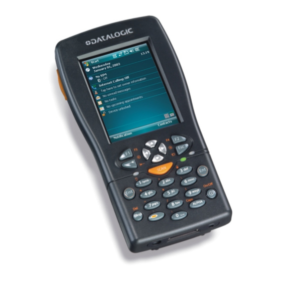
Page 15: General View
GENERAL VIEW Figure A – General View A) Data capture/Laser output window User programmable LED B) Scan key(s) (3) Backlit display C) Bluetooth® LED K) Mini SD card SLOT D) Charging status LED Microphone E) Backlit keyboard M) Latch release button External power supply connector N) Battery latch G) Communication/Charger connector... -
Page 17: Introduction
Thanks to a set of accessories, such as a vehicle cradle (standard and loud speaker), cigarette lighter power adapter, dashboard mounting kit, with state-of-the- art technology inside the PDA, the Datalogic J Series is the right answer for all data management needs on the move. -
Page 18: Available Models
+ RFID • compute options : O.S. version, microprocessor type/speed, memory size (fixed) For further details about the Datalogic J Series™ PDA models refer to the web site: www.mobile.datalogic.com. PACKAGE CONTENTS The Datalogic J Series™ PDA package contains: −... - Page 19 INTRODUCTION Rechargeable battery packs are not initially charged. Therefore the first operation to perform is to charge them. See paragraph 4.1. NOTE...
-
Page 20: Inserting Mini Sd Card
DATALOGIC J SERIES™ INSERTING MINI SD CARD With Datalogic J Series™ PDA, it is possible to add a Mini SD Card for additional storage capacity. To access the Mini SD card slot, unscrew the cover at the side of Datalogic J Series (see Figure A) and then proceed as follows:... - Page 21 INTRODUCTION Follow proper ESD precautions to avoid damaging the SD. Proper ESD precautions include, but are not limited to, working on an ESD mat and ensuring that the operator is properly grounded. CAUTION Do not force the card. If you feel resistance, remove the card, check the orientation, and reinsert it.
-
Page 22: Installing The Sim Card
DATALOGIC J SERIES™ INSTALLING THE SIM CARD To correctly insert the SIM Card, proceed as follows: Turn off the Datalogic J Series™ PDA. Press the latch release button and pull the battery latch down as indicated in the figures below:... - Page 23 INTRODUCTION Open the Sim Card slot by pulling up the locking plate. Pull up the cardholder and insert the Sim Card with its contacts downward and its round corner at the bottom. Lock the card into place by pushing the cardholder down and then pulling the locking plate down.
-
Page 24: Removing The Sim Card
DATALOGIC J SERIES™ 1.5.1 Removing the SIM Card To remove the SIM card, follow the steps above to access the SIM area, and remove it from its slot. All the basic functionalities normally associated to the SIM card are managed by the terminal (GPRS connectivity, phone calls, SMS handling). -
Page 25: Accessories
94ACC1293 DLJS Standard Battery (Li-Ion battery pack 1070 mAh@7.4 V) 94ACC1294 DLJS Large Capacity Battery (Li-Ion battery pack 1800 mAh@7.4 V) Power Supply 94ACC1286 PG12-10P35 AC/DC Power Supply without cord for Datalogic J Series™ 94ACC1296 PG12-10P35 AC/DC Power supply EU KIT 94ACC1297 PG12-10P35 AC/DC Power supply UK KIT... -
Page 26: Operating System
NOTE OPERATING SYSTEM Datalogic J Series™ comes in two different models, respectively supporting Windows CE and Windows Mobile. For further information regarding Windows Mobile refer to the website: http://www.microsoft.com/windowsmobile. -
Page 27: Connections
CONNECTIONS CONNECTIONS RS232/USB DIRECT CONNECTION You can use a cable to connect the Datalogic J Series™ PDA to a host computer to transfer data. Key: Host computer RS232 cable or USB cable Datalogic Series™ *Power Supply (only necessary for battery charging) -
Page 28: Wlan Connection
DATALOGIC J SERIES™ WLAN CONNECTION Datalogic J Series™ Wi-Fi 802.11b and Wi-Fi 802.11b/g models can communicate with the host using the on-board radio frequency module and an Access Point connected to the host computer. For models using the WiFi7 radio (7xx-xxx-xxx models), you can find information about the applet for radio configuration: http://www.summitdatacom.com/SCU.htm. - Page 29 CONNECTIONS Wi-Fi module is on by default. In order to avoid wasting energy, you can switch it off using the Wireless Communications applet (see par. 3.8.4). To start configuring your WLAN connection, tap the Wi-Fi icon at the bottom of the screen. NOTE Suspending the terminal powers off the 802.11b/g radio and drops the radio connection.
-
Page 30: Wpan Connection
DATALOGIC J SERIES™ WPAN CONNECTION ® Datalogic J Series™ PDAs can communicate with a Bluetooth device, such as a ® printer, within a range of 10 m, using the on-board Bluetooth module. Key: A) Datalogic J Series™ PDA B) Bluetooth® printer In order to avoid wasting energy, the Bluetooth®... - Page 31 CONNECTIONS Area coverage and Bluetooth® radio performance may vary, due to environmental conditions or interference caused by other devices (microwave ovens, radio transmitters, etc.), etc. NOTE...
-
Page 32: Wwan Connection
DATALOGIC J SERIES™ WWAN CONNECTION Datalogic J Series™ GSM/GPRS models enhance your connectivity solutions giving you an opening to an international wireless infrastructure that is the standard in Europe and Asia. GSM (Global System for Mobile communications) is a digital mobile phone system based on TDMA;... - Page 33 CONNECTIONS The GSM voice capability of this mobile computer has to be addressed to occasional use, in well covered areas. If the coverage is poor, the voice quality can be highly affected. NOTE In case of vehicle cradle installations, a good habit is to install the external microphone to minimize the risk of noises and echoes.
-
Page 34: Gps Connection
DATALOGIC J SERIES™ GPS CONNECTION Datalogic J Series™ GPS model provides a GPS Connection to allow for both satellite communications (if equipped) and geolocating abilities. The Global Positioning System (GPS) is a satellite-based navigation system made up of a network of 24 satellites that provides location and timing information around the globe. - Page 35 GPS reception may take a be slower; − if the Datalogic J Series™ GPS is in a building, parking lot, or a tunnel, the user will not receive any GPS signals. In order to avoid wasting energy, the GPS module is off by default. If you need to have GPS working, the module must be powered on using the External GPS applet (see par.
- Page 36 DATALOGIC J SERIES™ The user must ensure that the Datalogic J Series™ GPS is placed correctly for optimal GPS signal reception and stays in place. The GPS receiver can be tested in a stationary situation. NOTE Many modern vehicles have a heat reflective shield embedded in the windshield preventing good reception when the GPS receiver is placed on the dashboard.
- Page 37 CONNECTIONS Before using the Datalogic J Series™ GPS, the user should become familiar with the laws and regulations relating to satellite positioning in effect in the country in which he is driving. CAUTION The distances indicated by the Datalogic J Series™ GPS can differ slightly from those indicated on the road signs.
-
Page 38: Cradle Connections
DATALOGIC J SERIES™ CRADLE CONNECTIONS The Datalogic J Series™ can also communicate via RS232, USB and Ethernet, using various cradle models. For further details, refer to the specific cradle model User’s Manual. -
Page 39: Connection Cables
CONNECTIONS CONNECTION CABLES The following cables are listed with their order number. RS232 Direct Connection: 94A051008 WIN-NET SERIAL CABLE (HRS 3500-16P-CV) Datalogic J Series™ HOST/PC side side 9-pin (female) USB Direct Connection: 94A051009 WIN-NET USB CABLE (HRS 3500-16P-CV) Datalogic J Series™... -
Page 40: Use And Functioning
PDA STARTUP The Datalogic J Series™ PDA turns on when the battery pack or the external supply is inserted. After the battery pack is installed, use the [ON/OFF] key to turn the PDA on and off. - Page 41 USE AND FUNCTIONING When it is no longer used for more than a programmable timeout, which is defined in the POWER applet of the Control Panel, the PDA goes into power-off (low power with display and keyboard backlight off). In this mode it can be awakened (resuming operation) by the [ON/OFF] key.
-
Page 42: Windows Mobile Welcome Wizard
DATALOGIC J SERIES™ WINDOWS MOBILE WELCOME WIZARD In Windows Mobile, at the very first J Series™ startup, following a cold boot or following a registry restore to default values, the PDA startup (see par. 3.1) is preceded by the Welcome Wizard. -
Page 43: Using The Stylus
On the pop-up menu that appears, tap the action you want to perform. To recalibrate the touch screen use the Stylus Applet (see par. 3.8.7) Use only original Datalogic styluses supplied with the product itself. harsh applications,... -
Page 44: Data Capture
3.4.1 Laser Data Capture To scan barcodes, point the Datalogic J Series™ PDA laser model onto the code from a distance within the reading range while pressing one of the three SCAN Keys. See the reading diagrams in par. 5.2 for the reading range of your model. -
Page 45: Imager Data Capture
3.4.2 Imager Data Capture To read a 1D or 2D code, simply point the Datalogic J Series™ Imager model onto the code from a distance within the reading range (see par. 5.1, section Datalogic J Series™ Imager Optical Features) and press one of the three SCAN Keys. -
Page 46: Rfid Data Capture
3.4.3 RFID Data Capture To read or write a tag, place the Datalogic J Series™ PDA so that the RFID emission window is in front of and almost in contact with the tag, then press one of the three SCAN Keys or the application-defined key. -
Page 47: Description Of The Keys
USE AND FUNCTIONING DESCRIPTION OF THE KEYS The Datalogic J Series™ PDA provides a function-oriented keyboard having a total of 27 keys. The keyboard can be divided as follows: 2 Lateral SCAN keys (1 per side) System Control and Navigation... -
Page 48: Key Selection
DATALOGIC J SERIES™ 3.5.2 Key Selection The following figure shows the Datalogic J Series™ PDA keyboard: Some of these keys carry extra symbols and are logically divided in up to 3 sections according to the following figure: Each section corresponds to a symbol that can be obtained using the corresponding keyboard method according to the following scheme: A) function of the key when simultaneously pressed along with the Orange key;... - Page 49 USE AND FUNCTIONING It starts Data capture. The ORANGE key pressed simultaneously along with any other keyboard key enables the character positioned above or at its right/left side (in case of keys displayed at the top of keyboard). Ex: ORANGE key + [5 jkl] key corresponds to the character.
-
Page 50: Resetting The J Series
To perform a warm boot, press the following keys simultaneously: Cold Boot A cold boot is a complete reset of the J Series in which all applications are forcibly closed and the RAM is completely cleared. Registry is restored from persistent memory if a saved copy is available (see 3.8.2) and RAM file system is completely... -
Page 51: Windows Mobile
A clean boot restores the J Series to a clean configuration: both the registry and the file system return to a clean status that conform to factory default, unless the user has installed an additional package. - Page 52 DATALOGIC J SERIES™ Cold Boot A cold boot is a complete reset of the J Series in which all applications are forcibly closed and the RAM is completely cleared. Registry is restored from persistent memory if a saved copy is available (see Registry Applet, par. 3.8.2). Applications and data stored on file system are preserved.
-
Page 53: Status Indicators
USE AND FUNCTIONING STATUS INDICATORS 3.6.1 LED Status The Datalogic J Series™ provides three different LEDs signaling the PDA status. STATUS General Purpose Green/Red This LED is available to the application program. (left-side) Bluetooth® Blue blinking It blinks when the Bluetooth® module is... -
Page 54: Taskbar
DATALOGIC J SERIES™ 3.6.2 Taskbar As well as tasks opened in Windows, the Taskbar provides several status icons that report information about the time, the battery level, the keyboard function, and the decoding status. ICONS DESCRIPTION Time and Battery Icons It shows the time. - Page 55 USE AND FUNCTIONING Windows CE Taskbar Windows Mobile Taskbars...
-
Page 56: Data Capture Configuration
DATALOGIC J SERIES™ DATA CAPTURE CONFIGURATION From the Windows CE Taskbar, tap the "Decoding" icon to open a drop–down menu. Decoding can also be accessed from the Control Panel. By selecting the Info item from this drop-down menu you can access information about the Scanner and the Software;... - Page 57 USE AND FUNCTIONING The Scan Parameters are common to all scanner modules and allow control of the scanning device (i.e. beeper control, LED control, laser timeout, etc.). Each Data Capture screen window corresponds to a branch of the tree, and the name of the current branch is displayed at the bottom of each screen window.
-
Page 58: Reader Parameters
DATALOGIC J SERIES™ Selecting Data Capture Setup Parameters Alternatively using the stylus, you can tap once directly on the value on the right column; continue tapping until the desired value is reached. To activate a new configuration select the File ->Save Menu to send the new configuration to the barcode decoding software and save the new configuration. - Page 59 USE AND FUNCTIONING ContinuousMode: when enabled, the scanner can only be turned off by releasing the SCAN key, or if Soft Trigger is enabled, by the application program. Continuous Mode overrides Scan Timeout. KeyboardEmulation: if enabled all scanned data are transformed into keyboard events and can therefore be displayed and saved to a file as if input from the PDA keyboard.
-
Page 60: Default Settings
DATALOGIC J SERIES™ Default Settings The following tables contain the default values for the major barcode setup parameters, according to the type of scan engine mounted on the PDA. For a complete list of parameters and of their configuration procedures, please refer to the SDK Help file on the CD. - Page 61 USE AND FUNCTIONING BARCODE SYMBOLOGY SPECIFIC HP Laser Imager RFID+Laser READER PARAMETERS Enabled Disabled Plessey Disabled Code 93 Disabled Enabled Disabled Code 11 Disabled PDF - 417 Enabled Data Matrix Enabled Enabled POSTNET PLANET Japan Post Disabled* Australia Post KIX Code Royal Mail Code (RM4SCC) *These codes may be enabled individually but are disabled as a group.
-
Page 62: Capture
DATALOGIC J SERIES™ 3.7.2 Capture The Data Capture applet (Capture) enables code reading. Data Capture Window Data Capture can also be enabled through the Configuration applet by selecting File ->Scanner from the main menu, or by enabling the parameter Scan Always On in the Scan Parameters branch. -
Page 63: Control Panel
USE AND FUNCTIONING CONTROL PANEL From the Windows CE Desktop, double tap on the "My Device" icon and then double tap on the "Control Panel" icon to open the Windows CE control panel main window. The Control Panel can also be launched from Start ->Settings ->Control Panel. APPLET programs are displayed as icons;... -
Page 64: Buttons
DATALOGIC J SERIES™ 3.8.1 Buttons The BUTTONS Applet allows assigning desired applications to be launched by one of the function keys (F1, F2, F3, F4). Windows CE Buttons Icon Windows Mobile Buttons Icon On a Windows Mobile unit the user is also able to assign a shortcut to a function key. - Page 65 USE AND FUNCTIONING Select the “Enable Multipress” check box to enable multipress text input mode. F5, F6, F7, F8, F9, F10 function keys To enables , you need to change the ORANGE key mapping. Select the “F5-F10” check box: Windows CE Windows Mobile If pressed along with keys [5 jkl], [6 mno], [7 pqrs], [8 tuv], [9 wxyz], [0 ], the F5, F6, F7, F8, F9, F10 function keys.
-
Page 66: Registry
DATALOGIC J SERIES™ 3.8.2 Registry The REGISTRY ADMIN applet provides management of Windows CE/ Windows Mobile registry. From the Windows CE control panel main window, select the REGISTRY ADMIN applet by double tapping the Registry Admin icon. From the Windows Mobile Start menu, tap Settings -> System ->Registry. Select the REGISTRY ADMIN applet by tapping the Registry Admin icon. -
Page 67: Files Admin
USE AND FUNCTIONING 3.8.3 Files Admin The FILES ADMIN applet enables control of the permanence of files in the Windows CE System Folder. Because Windows Mobile mounts the entire file system in persistent store (rather than using RAM), it provides both users and applications with a reliable storage platform even in the absence of battery power. - Page 68 DATALOGIC J SERIES™ Select an installation file (for example, a .CAB cabinet file) from the Safe Setup mask. Safe Setup First Mask − Then select \Windows or a relevant sub-directory in the path box. Then, Safe Setup will recognize the new files and directories present in the \Windows directory, and will copy them to the \Backup\Windows directory.
-
Page 69: Wireless Communications
USE AND FUNCTIONING 3.8.4 Wireless Communications The WIRELESS COMMUNICATIONS applet provides management of the Wi-Fi ® Card, the Bluetooth and GSM/GPRS modules. Windows CE Wireless Communications Windows Mobile Connectivity Icon Icon If the PDA supports Windows CE, select the WIRELESS COMMUNICATIONS applet by double tapping the Wireless Communications icon from the Windows CE control panel main window. - Page 70 DATALOGIC J SERIES™ If the PDA supports Windows Mobile, the Wireless Manager application manages access to wireless connections. The 'Wireless Manager' is a sort of 'Control Panel' for bluetooth® and phone modules. From here it's possible to turn on or off bluetooth® and phone radio stacks.
-
Page 71: Gps Settings
Before purchasing, downloading or installing any GPS navigation software check with the software supplier that the application is compatible with the Datalogic J Series Refer to the application’s user guide for application installation and setup information. - Page 72 DATALOGIC J SERIES™ Tap Programs to choose the program port to be used to obtain GPS data:...
- Page 73 USE AND FUNCTIONING Tap Hardware to select the hardware port to which the GPS device is connected: Tap Access to manage access to the GPS device. Select the “Manage GPS automatically” check box to prevent some programs from obtain GPS data:...
- Page 74 DATALOGIC J SERIES™ Tap Advanced and select the “Enable GPS” check box to enable GPS. Select the “Enable GPS at reboot” check box to re-enable GPS after warm and cold boots:...
- Page 75 USE AND FUNCTIONING GPS Sample To start the GPS Sample, do the following steps: tap Start -> Programs -> GPS Sample:...
- Page 76 DATALOGIC J SERIES™ Tap GPS and select Start GPS to start the sample: As soon as the GPS receiver locates a position, all the GPS data will appear on the screen: To stop the sample, tap GPS and select Stop GPS.
-
Page 77: Ethernet Settings
3.8.6 Ethernet Settings Windows CE Ethernet Cradle Datalogic J Series™ can be connected to an Ethernet network by inserting it into the Datalogic J Series™ Ethernet Multi Cradle. Ethernet communication requires Datalogic J Series™ SW version 5.41 or later. Verify the software version by tapping on Software –... - Page 78 Control Panel. This applet is only visible when the mobile computer is correctly inserted into the Ethernet Multi Cradle. LAN icon Ethernet LANNDS1 Communications Window The IP Address belongs to Datalogic J Series™ while the MAC address is specific to each cradle slot.
-
Page 79: Windows Mobile Ethernet Cradle
USE AND FUNCTIONING Windows Mobile Ethernet Cradle Before using the ethernet cradle you have to un-check the 'COM1 Enable' option on the 'System Configuration' window (Start -> Programs -> System Configuration) and re-boot the unit. For internet browsing through the ethernet cradle ensure that programs that automatically connect to the internet should connect using 'My Work Network' ->... -
Page 80: Stylus Calibration
DATALOGIC J SERIES™ 3.8.7 Stylus Calibration You might need to recalibrate the touch screen (i.e. when you attempt to select one item with the stylus, another item is erroneously selected). To recalibrate the touch screen on Windows CE, complete the following steps: Select Start >... - Page 81 USE AND FUNCTIONING Figura 2 To recalibrate the touch screen on Windows Mobile, complete the following steps: Select Start > Settings > System > Screen to open the Screen Settings dialog as shown in Figure 3. Figure 3...
- Page 82 DATALOGIC J SERIES™ Tap Align Screen to open the Calibration screen shown in Figure 4. Carefully press and briefly hold stylus on the center of the target. Repeat as the target moves around the screen. Press the <ESC> key at any time to cancel the stylus calibration.
-
Page 83: Volume Settings
USE AND FUNCTIONING 3.8.8 Volume Settings From the Windows CE control panel main window, select the VOLUME SETTINGS applet by double tapping the Volume Settings icon. From the Windows Mobile Start Menu, tap Settings -> System -> Volume Settings. Select the VOLUME SETTINGS applet by tapping the Volume Settings icon. The Volume Settings applet allows managing the audio features and appears as follows: Volume Settings Window... -
Page 84: Output Tab
DATALOGIC J SERIES™ − GSM: it is automatically activated each time a phone-call is started. It is not available when using cradle loudspeaker this case Current Profile = Cradle). Output Tab It allows setting the volume for each audio profile: The “Master Volume”... - Page 85 USE AND FUNCTIONING Cradle Tab It allows selecting the cradle type and managing the vehicle cradle headset functioning: Two radio buttons allow selecting the type of cradle to be used. Check the “Cradle desk, AC plug or none” radio button, if using a cradle different from the vehicle cradle or an AC adapter plug.
- Page 86 DATALOGIC J SERIES™ Do not use the vehicle cradle headset if the headset button is disabled, since it may cause hearing damage. WARNING...
-
Page 87: Windows Connections
Datalogic J Series™ PDA and synchronize the information on them. Synchronization compares the data on the Datalogic J Series™ PDA with that on the desktop computer and updates both computers with the most recent information. - Page 88 DATALOGIC J SERIES™ In Windows Mobile before using the ActiveSync follow the directions described in 2.1 NOTE Visit the following Microsoft Web site for the latest in updates and technical information: http://www.microsoft.com/windowsmobile/activesync/default.mspx NOTE ActiveSync® Remote ® Microsoft® ActiveSync Remote is no longer supported in Windows CE.
-
Page 89: Bluetooth® Manager Device Setup
Series™ PDA you must perform the discovery procedure and enable the device as follows: ® Place the Bluetooth device within the range of the Datalogic J Series™ PDA (10 meters). From the “Control Panel” main window double tap on the “Bluetooth” applet to ®... - Page 90 DATALOGIC J SERIES™ Tap on the “Me” button to enter the related window; then, tap on the “ON” button ® to activate the Bluetooth module. The module activation may be also performed by using the WIRELESS COMMUNICATION applet as described in par. 3.8.4.
- Page 91 USE AND FUNCTIONING Once the Discovery procedure has been completed, select the desired ® Bluetooth device from the list. It is also possible to digit (12 hexadecimal digits) ® the Bluetooth address of the desired device by tapping on the “Add” button. The “Clear”...
- Page 92 DATALOGIC J SERIES™ Windows Mobile Bluetooth® Manager Device Setup Before turning on Bluetooth®, ensure that the two devices are within close range and that both Bluetooth-enabled devices are discoverable. Tap Start -> Settings -> Connections tab. Tap Bluetooth > Mode Select or clear the “Turn on Bluetooth”...
- Page 93 USE AND FUNCTIONING Tap the name of the other device, and tap Next: In Passkey, if you want to use a passkey (recommended for enhanced security), enter a alphanumeric passkey between 1 and 16 characters, and tap Next. Otherwise, leave the passkey blank, and tap Next:...
- Page 94 DATALOGIC J SERIES™ Enter the same passkey on the other device. To give the partnership a more meaningful name, change the name of the device in Name. Tap Finish. You can give a more meaningful name to a Bluetooth® partnership to help you recognize it when selecting from a list of partnerships.
- Page 95 USE AND FUNCTIONING Other devices with Bluetooth® capabilities can detect your device and attempt to beam information to it, establish a partnership, or use a Bluetooth® service. To make a device discoverable: Tap Start -> Settings -> Connections tab. Tap Bluetooth > Mode Tab. Select the “Turn on Bluetooth”...
- Page 96 DATALOGIC J SERIES™ If you no longer want your device to be discoverable, clear the “Make this device visible to other devices” check box. Your device will not detect and notify you of incoming Bluetooth® beams unless you set it up to do this. To receive a Bluetooth® beam: Tap Start ->...
-
Page 97: Ftp Server Setup
3.9.3 FTP Server Setup The Datalogic J Series™ Windows CE Operating System includes a sample File Transfer Protocol (FTP) server. FTP is used for copying files to and from remote computer systems over a network using TCP/IP. You can establish a connection to your Datalogic J Series™... -
Page 98: 3.10 Backup Directory File Management
DATALOGIC J SERIES™ 3.10 BACKUP DIRECTORY FILE MANAGEMENT All of the Windows CE system files reside in RAM (volatile memory) except for the Backup directory, which resides in FLASH (non-volatile memory). Therefore the contents of the Backup directory are persistent even if the PDA is re-booted or the battery pack is changed. -
Page 99: 3.11 Firmware Update For Windows Ce
USE AND FUNCTIONING 3.11 FIRMWARE UPDATE FOR WINDOWS CE The Datalogic J Series™ is equipped with a tool that implements a firmware update service. For further information, refer to DFU Reference Guide. -
Page 100: Maintenance
It is possible to recharge the battery pack by using the PG12-10P35 AC/DC external power supply directly connected to the Datalogic J Series™ PDA, see par. 2.1. Alternatively, it is also possible to recharge the battery pack by using the Datalogic J Series™ Single Cradle Desk or the Datalogic J Series™ Vehicle Cradle. -
Page 101: Replacing The Battery Pack
MAINTENANCE REPLACING THE BATTERY PACK To correctly replace the battery pack, proceed as follows: Turn off the Datalogic J Series™ PDA. Press the latch release button and pull the battery latch down as indicated in the figures below: Remove the battery pack:... - Page 102 Replace the battery pack by pressing the latch release button and pulling the battery latch down, and then by inserting it towards the speaker and pressing it into the Datalogic J Series™ PDA until the battery latch is automatically closed: When the latch release button is pressed, the PDA automatically shuts off, in order to retain data during the pack substitution.
- Page 103 MAINTENANCE Use only a Datalogic Mobile approved power supply. Use of an alternative power supply will void the product warranty and may cause product damage. Do not apply voltages to the batteries contacts. WARNING Risk of explosion if the battery is replaced by an incorrect type.
-
Page 104: Cleaning The Pda
To achieve the best battery life, turn off the radios not in use. NOTE CLEANING THE PDA Periodically clean the Datalogic J Series™ PDA with a slightly dampened cloth. Do not use alcohol, corrosive products or solvents. -
Page 105: Technical Features
TECHNICAL FEATURES TECHNICAL FEATURES TECHNICAL DATA Datalogic J Series™ Common Features Electrical Features Power DC supply 12 to 14 V ± 5% Battery pack 2 cell Li-Ion 1070 mAh@ 7.4 V (nominal) Large capacity pack 2 cell Li-Ion 1800 mAh@ 7.4 V (nominal) - Page 106 DATALOGIC J SERIES™ Environmental Features Working temperature ** -10° to + 50 °C / +14° to +122 °F Storage temperature -20° to +70 °C / -4° to +158 °F Humidity *** 90% non condensing for temperatures<40°C Protection IP64 ESD protection...
- Page 107 TECHNICAL FEATURES Datalogic J Series™ HP Laser / RFID +Laser Optical Features Optical Features Datalogic J Series™ Datalogic J Series™ HP Laser XXX-9XX-XXX Maximum resolution 0.13 mm / 5 mils 0.10 mm / 4 mils Skew angle ± 55 °...
- Page 108 DATALOGIC J SERIES™ Datalogic J Series™ Imager Optical Features Optical Features Max. resolution 1D Codes 0.10 mm / 4 mils 2D Codes 0.17 mm / 6.6 mils Skew angle ± 40 ° Pitch angle ± 35° Depth of field* 1D (linear):...
-
Page 109: Reading Diagrams
TECHNICAL FEATURES READING DIAGRAMS DLJS HP Laser (XXX-1XX-XXX models) Reading Zones (10° skew angle) 1.00 mm (40 mils) 0.50 mm (20 mils) 0.38 mm (15 mils) 0.25 mm (10 mils) 0.19 mm (7.5 mils) 0.13 mm (5 mils) 0.33 mm (13 mils) 800 mm DLJS SE950 Laser (XXX-9XX-XXX models) -
Page 110: Test Codes
DATALOGIC J SERIES™ 6 TEST CODES High Density Codes 0.25 mm (10 mils) !17162H! Code 39 17162 Ë"8NduÌ 2/5 Interleaved 0123456784 ÌtestwÎ Code 128 test x(0B2DE5*KKKKLM( EAN 13 (6450*TRMN( EAN 8... - Page 111 TEST CODES Medium Density Codes 0.38 mm (15 mils) !17162H! Code 39 17162 Ë"8NduÌ Interleaved 2/5 0123456784 ÌtestwÎ Code 128 test 100% x(0B2DE5*KKKKLM( EAN 13 100% (6450*TRMN( EAN 8...
- Page 112 DATALOGIC J SERIES™ Low Density Codes 0.50 mm (20 mils) !17162H! Code 39 17162 Ë"8NduÌ Interleaved 2/5 0123456784 ÌtestwÎ Code 128 test 120% x(0B2DE5*KKKKLM( EAN 13 120% (6450*TRMN( EAN 8...
-
Page 113: Glossary
GLOSSARY Access Point A device that provides transparent access between Ethernet wired networks and IEEE 802.11 interoperable radio-equipped mobile units. Hand-held terminals, PDAs or other devices equipped with radio cards, communicate with wired networks using Access Points (AP). The mobile unit (PDA), may roam among the APs in the same subnet while maintaining a continuous, seamless connection to the wired network. - Page 114 EEPROM Electrically Erasable Programmable Read-Only Memory. An on-board non-volatile memory chip. Flash Disk Non-volatile memory for storing application and configuration files. Global System for Mobile communication. It is a standard for digital cellular communications, currently used in the 900 MHz and 1800 MHz bands. GPRS General Packet Radio Service.
- Page 115 business use, often for keeping schedule calendars and address book information handy. Random Access Memory. Data in RAM can be accessed in random order, and quickly written and read. Radio Frequency. RFID (Radio frequency identification) A technology that incorporates the use of electromagnetic or electrostatic coupling in the radio frequency (RF) portion of the electromagnetic spectrum to uniquely identify an object, animal, or person.
-
Page 116: Index
Imager Data Capture; 29 PDA Startup; 24 Laser Data Capture; 28 Power Supply; vi RFID Data Capture; 30 Data Capture Configuration; 40 Datalogic J Series™ PDA Reader Parameters; 42 Description; 1 Reading Diagrams; 93 Default Settings; 44 Reference Documentation; v Description of the Keys;... - Page 117 Replacing the Batteries; 85 Technical Features; 89 Resetting the J Series; 34 Test Codes; 94 Safe Setup; 51 Using the Stylus; 27 Safety Regulations; vi Laser Safety; vii Radio Compliance; x Vocal Communication; 67 SAR Compliance; xii Volume Settings; 67 WEEE Compliance;...
- Page 118 Datalogic Mobile S.r.l. Via San Vitalino 13 40012 - Lippo di Calderara Bologna - Italy dichiara che declares that the déclare que le bescheinigt, daß das Gerät declare que el DLJS XXX-YYY-ZZZ e tutti i suoi modelli and all its models et tous ses modèles...
- Page 119 ETSI EN 300 328 1.7.1, O 2006 : CTOBER LECTROMAGNETIC COMPATIBILITY ADIO SPECTRUM (ERM); W ATTERS IDEBAND TRANSMISSION SYSTEMS 2,4GH TRANSMISSION EQUIPMENT OPERATING IN THE BAND AND USING WIDE BAND MODULATION TECHNIQUES ARMONIZED COVERING ESSENTIAL REQUIREMENTS UNDER ARTICLE R&TTE D IRECTIVE ETSI EN 300 330-2 1.3.1, A...
- Page 120 World wide Sales Network available from: www.mobile.datalogic.com/contacts Datalogic Mobile S.r.l. Via S. Vitalino, 13 40012 Lippo di Calderara di Reno Bologna - Italy Telephone: (+39) 051-3147011 Fax: (+39) 051-3147561 822000648 (Rev. I) ©2004-2009 Datalogic Mobile S.r.l. 12/09...
Need help?
Do you have a question about the J Series and is the answer not in the manual?
Questions and answers