Table of Contents
Advertisement
Quick Links
Advertisement
Table of Contents

Related Manuals for Kramer FC-7501


Summary of Contents for Kramer FC-7501
-
Page 1: User Manual
Kramer Electronics, Ltd. USER MANUAL Model: FC-7501 Analog Video to SDI Converter... -
Page 2: Table Of Contents
Figure 2: Connecting an FC-7501 Analog Video to SDI Converter Figure 3: Removing the Cover of the FC-7501 Figure 4: Upgrading the FC-7501 to FC-7501P by inserting an optional 7501M module 7 Tables Table 1: Front Panel FC-7501 Analog Video to SDI Converter... -
Page 3: Introduction
GROUP 6: Accessories and Rack Adapters; GROUP 7: Scan Converters and Scalers; and GROUP 8: Cables and Connectors 2 Download up-to-date Kramer user manuals from our Web site at http://www.kramerelectronics.com 3 The complete list of Kramer cables is on our Web site at http://www.kramerelectronics.com... -
Page 4: Overview
Overview Overview The high quality FC-7501 is a multi-standard converter that converts professional quality video to serial digital video (SDI). The following analog formats are supported: Composite video s-Video Component video (Y, B-Y, R-Y, sometimes called YUV or Y, Pb,... -
Page 5: Your Analog Video To Sdi Converter
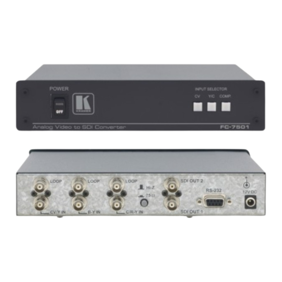
Your Analog Video to SDI Converter Figure 1, Table 1, and Table 2, define the FC-7501: Figure 1: FC-7501 Analog Video to SDI Converter Table 1: Front Panel FC-7501 Analog Video to SDI Converter... -
Page 6: Using Your Analog Video To Sdi Converter
VCR) to the component video BNC input connectors, Y, B-Y, and R-Y. 2. Connect both SDI outputs to SDI acceptors as follows (when only one SDI output is required, use either of the SDI outputs of the FC-7501, and leave the other SDI output unconnected):... -
Page 7: Figure 2: Connecting An Fc-7501 Analog Video To Sdi Converter
Using Your Analog Video to SDI Converter 5. Turn on the power and press the COMP. (Component video) button. The component video signal converts to SDI at both SDI OUT 1 and SDI OUT 2. Figure 2: Connecting an FC-7501 Analog Video to SDI Converter... -
Page 8: Upgrading The Fc-7501 To An Fc-7501P
Inserting the 7501M Module 1. Unfasten the two pairs of screws on each side of the cover of the FC-7501 and remove the cover, as Figure 3 illustrates: Figure 3: Removing the Cover of the FC-7501 2. -
Page 9: Figure 4: Upgrading The Fc-7501 To Fc-7501P By Inserting An Optional 7501M Module
Upgrading the FC-7501 to an FC-7501P Figure 4: Upgrading the FC-7501 to FC-7501P by inserting an optional 7501M module 4. Replace the cover on the FC-7501, and secure it in place by fastening the two pairs of screws on each side of the cover. -
Page 10: Technical Specifications
On the PC side, short pins 4 and 6 On the PC side, short pins 1, 7 and 8. 1 Specifications are subject to change without notice 2 VER-0.3, 20/01/03. Download the Communication Protocol FC-7501 from our Web site at http://www.kramerelectronics.com KRAMER: SIMPLE CREATIVE TECHNOLOGY... -
Page 11: Table 4: Structure Of The Protocol
This protocol complements Kramer’s “Protocol 2000” (Kramer’s switcher protocol), so the two protocols can co-exist without disturbing one another. (According to Protocol 2000, the FC-7501 appears as machine number 22, so care should be taken not to set a switcher with this machine number). -
Page 12: Description Of Instructions
Communications Protocol for the FC-7501 Description of Instructions INSTRUCTION 0 – RESET DATA=0: initialize the machine. When the machine is initialized, it will send the RESET code (DATA = 0). If the machine receives this code, it will reset to its “power-up”... - Page 13 Communications Protocol for the FC-7501 INSTRUCTION 12 – WRITE I²C DATA = I²C sub-address; EXTENDED DATA = data to be written to this sub-address. The PC sends I²C data (to the I²C address which was last accessed via INSTRUCTION 13). The machine replies by sending the same data back to the PC.
- Page 14 KRAMER: SIMPLE CREATIVE TECHNOLOGY...
- Page 15 For the latest information on our products and a list of Kramer distributors, visit our Web site: www.kramerelectronics.com where updates to this user manual may be found. We welcome your questions, comments and feedback. Safety Warning: Disconnect the unit from the power supply before opening/servicing.
Need help?
Do you have a question about the FC-7501 and is the answer not in the manual?
Questions and answers