Table of Contents
Advertisement
Quick Links
Advertisement
Table of Contents

Subscribe to Our Youtube Channel
Related Manuals for Kramer FC-7402


Summary of Contents for Kramer FC-7402
- Page 1 Kramer Electronics, Ltd. USER MANUAL Model: FC-7402 SDI to Analog Converter...
-
Page 2: Table Of Contents
Table 2: Rear Panel FC-7402 SDI to Analog Converter Table 3: Dipswitch Definitions Table 4: Dipswitch Settings (AUTO, PAL, and NTSC) Table 5: Technical Specifications of the FC-7402 SDI to Analog Converter Table 6: Structure of the Protocol Table 7: Instruction Set for the FC-7402... -
Page 3: Introduction
GROUP 6: Accessories and Rack Adapters; GROUP 7: Scan Converters and Scalers; and GROUP 8: Cables and Connectors 2 Download up-to-date Kramer user manuals from the Internet at this URL: http://www.kramerelectronics.com/manuals.html 3 The complete list of Kramer cables is on our Web site at http://www.kramerelectronics.com (click “Cables and Connectors” in the Products section) -
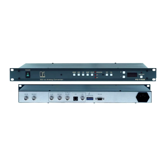
Page 4: Your Fc-7402 Sdi To Analog Converter
(often associated with low quality cables) • Avoid interference from neighboring electrical appliances that may adversely influence signal quality • Position your Kramer FC-7402 in a location free from moisture and away from excessive sunlight and dust Your FC-7402 SDI to Analog Converter... -
Page 5: Using Your Fc-7402 Sdi To Analog Converter
RS-232 Port Power Connector with Fuse Using Your FC-7402 SDI to Analog Converter You can use your FC-7402, to convert SDI video to professional quality analog video—composite video, s-Video and component video—as the example in Figure 2 illustrates. 1 For RGB video, connect all 3 connectors: G, B, and R... -
Page 6: 5.1 Connecting The Fc-7402 Sdi To Analog Converter
Set the dipswitches (see section 5.1.2). Connect the AC power cord. Figure 2: Connecting an FC-7402 SDI to Analog Converter 1 When only one output is required, connect that output of the FC 7402, and leave the other outputs unconnected... -
Page 7: Connecting A Pc
To connect a PC to the FC-7402 unit, using the Null-modem adapter provided with the machine (recommended): • Connect the RS-232 DB9 rear panel port on the FC-7402 unit to the Null-modem adapter and connect the Null-modem adapter with a 9 wire flat... -
Page 8: Dipswitch Settings
Using Your FC-7402 SDI to Analog Converter 5.1.2 Dipswitch Settings Configure the FC-7402 unit by setting the 8 dipswitches, as Table 3 defines: Dipswitch Set as follows: ON for RGB, OFF for YUV ON to enable Vertical Interval Blanking; OFF to disable PEDESTAL ON for pedestal (7.5 IRE offset selection for NTSC);... -
Page 9: Adjusting Oversampling To X2 (Moving Jumper Jmp1)
Set DIP 4 OFF and remove the power cord. Open the FC-7402 unit and move Jumper JMP1 to the left (see Figure 4). Close the FC-7402 unit, set DIP 4 ON and connect the power cord to the mains electricity. -
Page 10: 5.2 Operating The Fc-7402 Sdi To Analog Converter
• RS-232 serial commands transmitted by a touch screen system, PC, or other serial controller To operate the FC-7402 using the front panel buttons, do the following: Turn on the power. The signal from the SDI source is automatically converted to composite video, s-Video, and component video (YUV if DIP 1 is set to OFF, or RGB if DIP 1 is set to ON). -
Page 11: Locking The Front Panel
Locking the Front Panel To prevent changing the settings accidentally or tampering with the front panel, lock your FC-7402. Unlocking releases the protection mechanism. To lock the FC-7402: • Press the PANEL LOCK button (for about 2 seconds) until the PANEL LOCK LED illuminates freezing the front panel controls. -
Page 12: Communication Protocol
Communication Protocol RS-232 communication between the FC-7402 and the PC is done using the following protocol. The protocol uses four bytes of information, and data is at 9600 baud, no parity, 8 data bits and 1 stop bit. The controller and machine should be connected via... - Page 13 Note that the video parameter values range from 0 (minimum) up to 255dec (maximum), and do not necessarily correspond with the number displayed on the panel of the FC-7402. If a value outside the legal range of a particular parameter is sent, the error code will be returned.
- Page 14 2 = PAL 3 = PAL-N 64dec (40hex)= Invalid or no input detected Note that when the DIP-switches are set for a fixed standard, the FC-7402 will reply by sending the code for the fixed standard. INSTRUCTION 16dec – ERROR If the machine receives an invalid instruction, it replies by sending this error code.
- Page 15 EXCLUSION OF DAMAGES The liability of Kramer for any effective products is limited to the repair or replacement of the product at our option. Kramer shall not be liable for: Damage to other property caused by defects in this product, damages based upon inconvenience, loss of use of the product, loss of time, commercial loss;...
- Page 16 For the latest information on our products and a list of Kramer distributors, visit our Web site: www.kramerelectronics.com. Updates to this user manual may be found at http://www.kramerelectronics.com/manuals.html. We welcome your questions, comments and feedback. Kramer Electronics, Ltd. 3 Am VeOlamo Street. Jerusalem 95463, Israel Tel: (+972-2)-654-4000 Fax: (+972-2)-653-5369, E-mail: info@kramerel.com...
Need help?
Do you have a question about the FC-7402 and is the answer not in the manual?
Questions and answers