
Related Manuals for Westinghouse WH2000i Series


Summary of Contents for Westinghouse WH2000i Series
- Page 1 Digital Inverter Generator Owner’s Manual Manual del Propietario WH1000i WH2000i Series...
-
Page 2: California Proposition 65 Warning
California California Proposition 65 Warning Proposition 65 Warning The engine exhaust from this product Certain components in this product and its contains chemicals known to the state of related accessories contain chemicals California to cause cancer, birth defects known to the state of California to cause or other reproductive harm. -
Page 3: Congratulations On Owning A Westinghouse Inverter
Purchase Receipt: (retain your purchase receipt to ensure trouble-free warranty coverage) Product Registration To ensure trouble-free warranty coverage, it is important you register your Westinghouse inverter. You can register your inverter by either: 1. Filling in the product registration form below and mailing to:... -
Page 5: Table Of Contents
SAFETY DEFINITIONS ............................7 SAFETY SYMBOL DEFINITIONS ........................7 GENERAL SAFETY RULES ..........................8 SAFETY LABELS AND DECALS – WH1000i ....................10 SAFETY LABELS AND DECALS – WH2000i SERIES ..................12 SAFETY LABELS AND DECALS – WH2000iXLT .....................14 UNPACkING ................................16 UNPACKING THE INVERTER ..........................16 Components: ..............................16 FEATURES ................................17... - Page 6 Storage Procedure for 1 – 3 Months ......................41 Storage Procedure for Greater Than 3 Months ..................42 SERVICE PARTS ..............................44 WH1000i Service Parts ..........................44 WH2000i Series Service Parts ........................46 TROUbLESHOOTING ............................48 TROUBLESHOOTING ............................48 WARRANTY ................................49 WESTPRO POWER SYSTEMS “TWO YEAR” LIMITED WARRANTY .............49 WESTPRO’S RESPONSIBILITY ........................49...
-
Page 7: Safety
SAFETY saFEtY DEFinitions saFEtY sYMBol DEFinitions The words DANGER, WARNING, CAUTION and NOTICE are used throughout this manual to highlight important information. Be certain that the meanings of Symbol Description these alerts are known to all who work on or near the equipment. -
Page 8: General Safety Rules
SAFETY gEnEral saFEtY rulEs WARNING Gasoline and gasoline vapors are DANGER extremely flammable and explosive Never use the inverter in a location under certain conditions. that is wet or damp. Never expose the • Always refuel the inverter outdoors, inverter to rain, snow, water spray or in a well-ventilated area. - Page 9 SAFETY WARNING Never operate the inverter if powered items overheat, electrical output drops, there is sparking, flames or smoke coming from the inverter, or if the receptacles are damaged. Never use the inverter to power medical support equipment. Always remove any tools or other service equipment used during maintenance from the inverter before operating.
-
Page 10: Safety Labels And Decals - Wh1000I
SAFETY saFEtY laBEls anD DECals – wH1000i FRONT BACK Figure 1... - Page 11 SAFETY Figure 2...
-
Page 12: Safety Labels And Decals - Wh2000I Series
SAFETY saFEtY laBEls anD DECals – wH2000i sEriEs FRONT BACK Figure 3... - Page 13 SAFETY Figure 4...
-
Page 14: Safety Labels And Decals - Wh2000Ixlt
SAFETY saFEtY laBEls anD DECals – wH2000iXlt FRONT BACK Figure 5... - Page 15 SAFETY Figure 6...
-
Page 16: Unpacking
UNPACKING unPaCKing tHE invErtEr CAUTION Always have assistance when lifting the inverter. The inverter is heavy; lifting it could cause bodily harm. Avoid cutting on or near staples to prevent personal injury. Tools required – box cutter or similar device. 1. -
Page 17: Features
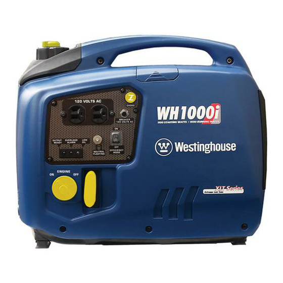
FEATURES gEnEral invErtEr FEaturEs – wH1000i Figure 7 1 - Control Panel: Contains the reset breaker, 5 - Fuel Cap and Vent: Open the vent to run the outlets and warning lights. engine and close the vent when the engine is off. 2 - Spark Plug Access Cover: Remove the 6 - Engine Service Panel: Remove the panel to cover to service the spark plug. -
Page 18: Control Panel Features - Wh1000I
FEATURES Control PanEl FEaturEs – wH1000i Figure 8 – Control Panel Features 1 - 120-Volt, 20-Amp Duplex Outlet (NEMA 5 - Ground Terminal: The ground terminal is used 5-20R): The outlet is capable of carrying a to externally ground the inverter. maximum of 20 amps. -
Page 19: General Inverter Features - Wh2000I Series
FEATURES gEnEral invErtEr FEaturEs – wH2000i sEriEs Figure 9 1 - Control Panel: Contains the reset breaker, 6 - Engine Oil Fill/Drain Plug Service Panel: outlets and warning lights. Remove the panel to access the engine oil fill/ drain plug for maintenance. -
Page 20: Control Panel Features - Wh2000I Series
FEATURES Control PanEl FEaturEs – wH2000i sEriEs Figure 10 – Control Panel Features 1 - 120-Volt, 20-Amp Duplex Outlet (NEMA 4 - Output Ready LED: The light will be green 5-20R): The outlet is capable of carrying a when the inverter is ready to be used. -
Page 21: General Inverter Features - Wh2000Ixlt
FEATURES gEnEral invErtEr FEaturEs – wH2000iXlt Figure 11 1 - Control Panel: Contains the reset breaker, 6 - Engine Oil Fill/Drain Plug Service Panel: outlets and warning lights. Remove the panel to access the engine oil fill/ drain plug for maintenance. 2 - 12-Volt DC Power Socket: Provides 12-volt DC power up to 8 amps. -
Page 22: Control Panel Features - Wh2000Ixlt
FEATURES Control PanEl FEaturEs – wH2000iXlt Figure 12 – Control Panel Features 1 - 120-Volt, 20-Amp Duplex Outlet (NEMA 5 - Output Ready LED: The light will be green 5-20R): The outlet is capable of carrying a when the inverter is ready to be used. maximum of 20 amps. -
Page 23: Operation
OPERATION BEForE starting tHE Weather – Never operate your inverter outdoors during rain, snow or any combination of weather conditions invErtEr that could lead to moisture collecting on, in or around the inverter. Dry Surface – Always operate the inverter on a dry before starting the inverter, review surface free of any moisture. -
Page 24: Inverter Paralleling Operation
DANGER Never connect the paralleling cord to 1. Using only the Westinghouse paralleling cord (Part the inverters with the inverters running. No. 260041) with both cord switches set to OFF The inverters must not be running and... -
Page 25: Initial Oil Fill
OPERATION WH1000i 2. Start one of the inverters and wait until the ready light is on. 1. Loosen the screw and remove the engine service 3. Turn both cord switches to ON (I). panel to access the oil fill/drain plug (see Figure 16). -
Page 26: Wh2000I Series
Figure 20 – Engine Oil Correct Level 7. Do not overfill. If oil level is too high, oil will drain out through the fill plug. WH2000i Series 1. Loosen the screw and remove the engine oil fill/ drain plug service panel to access the oil fill/drain plug (see Figure 21). - Page 27 OPERATION 2. Clean the area around the oil fill/drain plug and NOTICE remove plug (see Figure 22). Do not tilt the inverter to add oil. It must be filled on a flat, level surface. 4. Add the 200 ml of oil to the engine (see Figure 24).
-
Page 28: Adding / Checking Engine Fluids And Fuel
OPERATION aDDing / CHECKing EnginE Adding Gasoline to the Fuel Tank FluiDs anD FuEl WARNING Never refuel the inverter while the before adding/checking engine engine is running. fluids and fuel, review Safety on page 7. Always turn the engine off and allow the inverter to cool before refueling. -
Page 29: Starting The Inverter
OPERATION NOTICE CAUTION The engine is equipped with a low oil shutdown Avoid prolonged skin contact with switch. If the oil level becomes low, the engine will gasoline. Avoid prolonged breathing of shut down and will not start until the oil is filled to the gasoline vapors. -
Page 30: Using Efficiency Mode
OPERATION Using Efficiency Mode 3. Pull the choke knob out to the ON position (see Figure 29). The inverter is equipped with an efficiency mode switch to minimize fuel consumption. In efficiency mode, the inverter will sense the load and adjust the engine RPM to the current load requirements. -
Page 31: Stopping The Inverter
OPERATION stoPPing tHE invErtEr Normal Operation During normal operation, use the following steps to stop your inverter: 1. Remove any connected loads from the control panel receptacles. 2. Allow the inverter to run at “no load” to reduce and stabilize engine and alternator temperatures. 3. -
Page 32: Maintenance
MAINTENANCE MaintEnanCE CAUTION before performing maintenance Avoid skin contact with engine oil or on the inverter, review Safety on gasoline. Prolonged skin contact with page 7 and the following safety engine oil or gasoline can be harmful. messages. Frequent and prolonged contact with engine oil may cause skin cancer. -
Page 33: Engine Oil Maintenance
MAINTENANCE EnginE oil MaintEnanCE Engine Oil Specification 1. Only use the engine oil specified in Figure 32. 2. Only use 4-stroke/cycle engine oil. NEVER USE 2-STROKE/CYCLE OIL. Synthetic oil is an acceptable substitute for conventional oil. 0°C 25°C SAE 5W-30 SAE 10W-30 SAE 15W-40 32°F... -
Page 34: Checking Engine Oil - Wh2000I Series
MAINTENANCE Checking Engine Oil – WH2000i Series NOTICE Always maintain proper engine oil level. Failure to maintain proper engine oil level could result in severe damage to the engine and/or shorten the life of the engine. Always use the specified engine oil. Failure to use the specified engine oil can cause accelerated wear and/or shorten the life of the engine. -
Page 35: Adding Engine Oil - Wh2000I Series
Never dispose of used engine oil by dumping the 9. Continue to add oil until the oil is at the correct oil into a sewer, on the ground, or into groundwater level. See Checking Engine Oil – WH2000i Series or waterways. Always be environmentally on page 34. -
Page 36: Changing Engine Oil - Wh2000I Series
Figure 40 – Draining Engine Oil 7. Allow oil to completely drain. 8. Fill crankcase with oil following the steps outlined in Adding Engine Oil – WH2000i Series on page 35. NOTICE Never dispose of used engine oil by dumping the oil into a sewer, on the ground, or into groundwater or waterways. -
Page 37: Cleaning The Air Filter - Wh2000I Series
MAINTENANCE Cleaning the Air Filter – WH2000i Series The air filter must be cleaned after every 50 hours of use or 3 months (frequency should be increased if inverter is operated in a dusty environment). 1. Turn off the inverter and let it cool for several minutes if running. -
Page 38: Draining The Float Bowl
MAINTENANCE Draining tHE Float Bowl 5. Wash the foam air filter element by submerging the element in a solution of household detergent soap and warm water. Slowly squeeze the foam to WH1000i thoroughly clean. 1. Remove the engine service panel to access the NOTICE carburetor. -
Page 39: Wh2000I Series
MAINTENANCE WH20001 Series 4. Allow fuel to drain into the container, and then tighten the float bowl drain screw. 1. Remove the engine service panel to access the float bowl drain. NOTICE Never dispose of fuel by dumping fuel into a sewer, on the ground, or into groundwater or waterways. - Page 40 MAINTENANCE 8. Inspect the spark plug for: NOTICE • Cracked or chipped insulator Never apply any side load or move the spark plug • Excessive wear laterally when removing the spark plug. Applying a side load or moving the spark plug laterally may crack • Spark plug gap of 0.032 in.
-
Page 41: Cleaning The Spark Arrestor
MAINTENANCE ClEaning tHE sParK 6. Pull the spark arrestor screen off the muffler exhaust pipe. arrEstor 7. Using a wire brush, remove any dirt and debris that may have collected on the spark arrestor screen. Check and clean the spark arrestor after every 100 hours of use or 6 months. -
Page 42: Storage Procedure For Greater Than 3 Months
Draining the Float Bowl on page 38. 5. Change the oil (see Changing Engine Oil – WH1000i on page 35) or Changing Engine Oil – WH2000i Series on page 36). 6. Remove the spark plug (see Spark Plug Maintenance on page 39) and place about 1 tablespoon of oil in the spark plug opening. - Page 43 MAINTENANCE This Page Intentionally Left blank...
-
Page 44: Service Parts
MAINTENANCE sErviCE Parts WH1000i Service Parts 9 10 Figure 54... - Page 45 MAINTENANCE Item WPP# Description 260028 Fuel Strainer 260007 Fuel Tank Cap Assy. 260002 Spark Plug Cover 260003 A5RTC (Torch) Spark Plug 260006 Choke Cable 260005 Reset Breaker 260014 Efficiency Mode Switch 260004 Recoil Starter 260001 Maintenance Door 260000 Air Cleaner Element 260015 Oil Filler Plug 260012...
-
Page 46: Wh2000I Series Service Parts
MAINTENANCE WH2000i Series Service Parts Figure 55... - Page 47 MAINTENANCE Item WPP# Description 260027 Indicator Lights 260005 Reset Breaker 260014 Efficiency Mode Switch 260021 Choke Cable 260039 12-volt DC Power Socket – WH2000iXLT Model 260020 Recoil Starter 260019 Spark Plug Cover 260003 A5RTC (Torch) Spark Plug 260017 Oil Filling Cover 260015 Oil Filler Plug 260018...
-
Page 48: Troubleshooting
TROUBLESHOOTING trouBlEsHooting WARNING before attempting to service or troubleshoot the inverter, the owner or service technician must first read the owner’s manual and understand and follow all safety instructions. Failure to follow all instructions may result in conditions that can lead to voiding of the EPA certification or product warranty, serious personal injury, property damage or even death. -
Page 49: Warranty
WESTPRO Westinghouse unit. Should a product difficulty occur, you must, at your expense, deliver or ship your WESTPRO Westinghouse unit to a WESTPRO Authorized Service Dealer for warranty repairs (which must occur within the applicable warranty period), and arrange for pick-up or return of your unit after the repairs have been made. -
Page 50: Non-Warrantable Applications
FOR A PARTICULAR PURPOSE OR USE and any implied warranty of MERCHANTABILITY otherwise applicable to WESTPRO’s Westinghouse line of inverters. WESTPRO and its affiliated companies shall not be liable for any special, incidental or consequential damage, including lost profits. There are no warranties extended other than as provided herein. -
Page 51: Emissions Control Warranty
EMISSIONS CONTROL WARRANTY FEDEral and/or CaliFornia EMission Control warrantY statEMEnt YOUR WARRANTY RIGHTS AND ObLIGATIONS Westpro Power Systems, LLC, the United States Environmental Protection Agency (EPA), and, for those products certified for sale in the state of California, the California Air Resources Board (CARB) are pleased to explain the emission control system (ECS) warranty on your [current model year 2014]* small off-road spark-ignited engine and equipment (the outdoor equipment). -
Page 52: Defects Warranty Requirements
EMISSIONS CONTROL WARRANTY DEFECTS WARRANTY REQUIREMENTS Westpro Power Systems, LLC warrants to the ultimate purchaser and each subsequent purchaser that the outdoor equipment engine is designed, built and equipped so as to conform with all applicable regulations; and free from defects in materials and workmanship that cause the failure of a warranted part, and is identical in all material respects to that part as described in the application for certification. -
Page 53: Warranted Parts
EMISSIONS CONTROL WARRANTY WARRANTED PARTS: The repair or replacement of any warranted part otherwise eligible for warranty coverage may be excluded from such warranty coverage if Westpro Power Systems, LLC demonstrates that the outdoor equipment has been abused, neglected, or improperly maintained, and that such abuse, neglect, or improper maintenance was the direct cause of the need for repair or replacement of the part. - Page 54 EMISSIONS CONTROL WARRANTY This Page Intentionally Left blank...
- Page 55 MANUAL DEL PROPIETARIO...
- Page 56 California California Proposition 65 Warning Proposition 65 Warning The engine exhaust from this product Certain components in this product and its contains chemicals known to the state of related accessories contain chemicals California to cause cancer, birth defects known to the state of California to cause or other reproductive harm.
-
Page 57: Felicitaciones Por Adquirir Un Inversor Westinghouse
Recibo de compra: (conserve el recibo de compra para asegurar la cobertura sin problemas de la garantía). Registro del producto: Para asegurar la cobertura sin problemas de la garantía es importante que registre el inversor Westinghouse. Puede registrarlo haciendo lo siguiente: 1. - Page 59 ÍNDICE FELICITACIONES POR ADqUIRIR UN INVERSOR WESTINGHOUSE ............3 Para sus registros: ............................3 Registro del producto: ..........................3 Formulario de registro del producto ......................3 SEgURIDAD ................................7 DEFINICIONES DE SEGURIDAD ........................7 DEFINICIONES DE LOS SÍMBOLOS DE SEGURIDAD ...................7 NORMAS GENERALES DE SEGURIDAD ......................8 ETIqUETAS Y CALCOMANÍAS DE SEGURIDAD –...
- Page 60 ÍNDICE ALMACENAMIENTO DE LARGO PLAzO .......................41 Procedimiento para almacenar la unidad durante 1 a 3 meses ..............41 Procedimiento para almacenar la unidad durante más de tres meses ............41 PIEzAS DE SERVICIO .............................42 Piezas de servicio del modelo WH1000i ....................42 Piezas de servicio de la serie WH2000i .....................44 SOLUCIóN DE PRObLEmAS ..........................46 SOLUCIÓN DE PROBLEMAS .........................46 gARANTíA ................................47...
-
Page 61: Seguridad
SEGURIDAD deFiniciones de deFiniciones de los seGuridad sÍMBolos de seGuridad Las palabras PELIGRO, ADVERTENCIA, Símbolo Descripción PRECAUCIÓN y AVISO se usan a lo largo de este manual para destacar la información importante. Asegúrese de que todo aquel que trabaje con el equipo Símbolo de alerta de seguridad o cerca de él conozca el significado de estas alertas. -
Page 62: Normas Generales De Seguridad
SEGURIDAD norMas Generales de ADVERTENCIA seGuridad La gasolina y los vapores de la gasolina son extremadamente inflamables PELIGRO y explosivos en determinadas condiciones. Nunca use el inversor en lugares • Siempre debe hacer la recarga mojados o húmedos. Nunca exponga de combustible del inversor en el inversor a lluvia, nieve, rociado de exteriores, en una zona bien... - Page 63 SEGURIDAD ADVERTENCIA Nunca opere el inversor si se sobrecalientan los componentes eléctricos, si cae la salida de energía eléctrica, si salen chispas, llamas o humo del inversor, o si los receptáculos están dañados. Nunca use el inversor para alimentar equipos de asistencia médica. Siempre retire del inversor las herramientas u otros equipos de servicio que se utilicen durante el...
-
Page 64: Etiquetas Y Calcomanías De Seguridad - Wh1000I
SEGURIDAD etiquetas Y calcoManÍas de seGuridad – WH1000i FRONT BACK Figura 1... - Page 65 SEGURIDAD Figura 2...
-
Page 66: Etiquetas Y Calcomanías De Seguridad - Serie Wh2000I
SEGURIDAD etiquetas Y calcoManÍas de seGuridad – serie WH2000i FRONT BACK Figura 3... - Page 67 SEGURIDAD Figura 4...
-
Page 68: Etiquetas Y Calcomanías De Seguridad - Wh2000Ixlt
SEGURIDAD etiquetas Y calcoManÍas de seGuridad – WH2000iXlt FRONT BACK Figura 5... - Page 69 SEGURIDAD Figura 6...
-
Page 70: Desembalar
DESEMBALAR procediMiento para deseMBalar el inversor PRECAUCIóN Siempre debe solicitar ayuda para levantar el inversor. El inversor es pesado, levantarlo puede causarle lesiones físicas. Evite cortar sobre o cerca de grapas para evitar lesiones personales. Herramientas requeridas: trincheta o dispositivo similar. -
Page 71: Características
CARACTERÍSTICAS caracterÍsticas Generales del inversor – WH1000i Figura 7 1 - Tablero de control: Contiene el disyuntor 5 - Tapa y ventilación del combustible: Abra la de reinicio, los tomacorrientes y las luces de ventilación para hacer andar el motor y cierre la advertencia. -
Page 72: Características Del Tablero De Control - Wh1000I
CARACTERÍSTICAS caracterÍsticas del taBlero de control – WH1000i Figura 8 – Características del tablero de control 1 - Tomacorrientes de 120 Voltios, 20 5 - Terminal de tierra: El terminal de tierra se usa Amperios Dúplex (NEmA 5-20R): El para conectar el inversor a tierra externamente. tomacorrientes tiene capacidad de suministrar 6 - LED de nivel bajo de aceite: La luz roja se 20 amperios como máximo. -
Page 73: Características Generales Del Inversor - Serie Wh2000I
CARACTERÍSTICAS caracterÍsticas Generales del inversor – serie WH2000i Figura 9 Tablero de control: Contiene el disyuntor de reinicio, los Tablero de servicio del tapón de llenado/drenaje de aceite del motor: Extraiga el tablero para acceder al tomacorrientes y las luces de advertencia. tapón de llenado/drenaje de aceite del motor para el Perilla de cebado: jale hacia afuera hasta la posición mantenimiento. -
Page 74: Características Del Tablero De Control - Serie Wh2000I
CARACTERÍSTICAS caracterÍsticas del taBlero de control – serie WH2000i Figura 10 – Características del tablero de control 1 - Tomacorrientes de 120 Voltios, 20 4 - LED de salida lista: La luz será de color Amperios Duplex (NEmA 5-20R): El verde cuando el inversor esté... -
Page 75: Características Generales Del Inversor - Wh2000Ixlt
CARACTERÍSTICAS caracterÍsticas Generales del inversor – WH2000iXlt Figura 11 Tablero de control: Contiene el disyuntor de reinicio, los Tablero de servicio del tapón de llenado/drenaje de aceite del motor: Extraiga el tablero para acceder al tomacorrientes y las luces de advertencia. tapón de llenado/drenaje de aceite del motor para el Tomacorriente de 12 voltios DC: Brinda energía mantenimiento. -
Page 76: Características Del Tablero De Control - Wh2000Ixlt
CARACTERÍSTICAS caracterÍsticas del taBlero de control – WH2000iXlt Figura 12 – Características del tablero de control 1 - Tomacorrientes de 120 Voltios, 20 5 - LED de salida lista: La luz será de color Amperios Duplex (NEmA 5-20R): El verde cuando el inversor esté listo para su tomacorrientes tiene capacidad de suministrar uso. -
Page 77: Funcionamiento
FUNCIONAMIENTO antes de arrancar el No debe haber cargas conectadas: Compruebe que el inversor no tenga cargas conectadas antes inversor de encenderlo. Para asegurar que no haya cargas conectadas, desenchufe los prolongadores eléctricos que estén enchufados en los receptáculos del tablero de control. -
Page 78: Operación Paralela Con Conversores
PELIGRO conversores. No conecte el cable paralelo a los conversores cuando los conversores 1. Usando únicamente el cable paralelo Westinghouse están funcionando. Los conversores (Parte No. 260041) y siempre que ambos no deben estar funcionando y ambos interruptores del cable estén apagados (O), conecte... -
Page 79: Llenado De Aceite Inicial
FUNCIONAMIENTO llenado de aceite inicial AVISO El aceite del motor debe agregarse cuando el inversor esté sobre una superficie plana y nivelada, o se puede obtener una lectura inexacta. No llene en exceso. Si el motor se llena excesivamente con aceite, se pueden producir daños graves en el motor. -
Page 80: Serie Wh2000I
FUNCIONAMIENTO OTA: La capacidad de aceite para el 1000i es de Llene el recipiente con aceite nuevamente sólo hasta 400 ml. la marca correspondiente a 1.0. Mediante el uso del recipiente de llenado de aceite 6. Agregue los 100 ml de aceite al motor. Ahora, el y el aceite suministrados, llene el recipiente hasta la aceite debe estar en el nivel correcto (Vea Figura... - Page 81 FUNCIONAMIENTO 2. Limpie la zona que rodea el tapón de llenado/ Agregue los 200 ml de aceite al motor (Vea Figura drenaje de aceite y extraiga el tapón (Vea Figura 24). 22). Figura 22 – Tapón de llenado/drenaje de aceite Figura 24 –...
-
Page 82: Procedimiento Para Agregar/Controlar El Combustible Y Los Líquidos Del Motor
FUNCIONAMIENTO procediMiento para Procedimiento para agregar gasolina al depósito de combustible aGreGar/controlar el coMBustiBle Y los ADVERTENCIA lÍquidos del Motor Nunca haga la recarga de combustible del inversor mientras el motor está en marcha. Antes de agregar/controlar el combustible y los líquidos del motor, revise Seguridad en la página 7. -
Page 83: Arranque Del Inversor
FUNCIONAMIENTO AVISO PRECAUCIóN El motor cuenta con un interruptor de desconexión por Evite el contacto prolongado de la piel con nivel bajo de aceite. Si el nivel del aceite es bajo, el motor la gasolina. Evite respirar durante períodos se apagará y no arrancará hasta que se cargue aceite prolongados los vapores de la gasolina. -
Page 84: Uso Del Modo De Eficiencia
FUNCIONAMIENTO Uso del modo de eficiencia 3. Tire hacia afuera la perilla de cebado hasta la posición ON (encendido) (Vea Figura 29). El inversor cuenta con un interruptor de modo de eficiencia para minimizar el consumo de combustible. En el modo de eficiencia, el inversor detecta la carga y ajusta las RPM del motor según los requisitos de carga actual. -
Page 85: Restablecimiento Del Disyuntor
FUNCIONAMIENTO Restablecimiento del disyuntor de reinicio El inversor activa el disyuntor y se desconecta automáticamente de la carga cuando los controles detectan una condición de sobrecarga predeterminada. El motor del inversor continúa en funcionamiento pero no habrá ninguna salida eléctrica. 1. -
Page 86: Mantenimiento
MANTENIMIENTO ManteniMiento PRECAUCIóN Antes de realizar tareas de Evite que la piel esté en contacto con el mantenimiento del inversor, analice aceite del motor o la gasolina. El contacto Seguridad en la página 7 y los prolongado de la piel con el aceite del siguientes mensajes de seguridad. -
Page 87: Mantenimiento Del Aceite Del Motor
MANTENIMIENTO ManteniMiento del aceite del Motor Especificación del aceite del motor Utilice únicamente el aceite de motor especificado en Figura 32. Utilice únicamente aceite para motor de 4 tiempos/ciclos. NUNCA UTILICE ACEITE DE MOTOR DE 2 TIEMPOS. El aceite sintético es un sustituto aceptable para el aceite convencional. -
Page 88: Procedimiento Para Controlar El Aceite Del Motor - Serie Wh2000I
MANTENIMIENTO Procedimiento para controlar el aceite • Si el nivel de aceite es bajo, agregue hasta el nivel correcto utilizando la botella de llenado de aceite del motor – Serie WH2000i suministrada. No llene excesivamente el cárter del aceite. AVISO Mantenga siempre un nivel de aceite del motor adecuado. -
Page 89: Procedimiento Para Agregar El Aceite Del Motor - Serie Wh2000I
MANTENIMIENTO Continúe agregando aceite hasta que esté en el nivel Con una tela húmeda, limpie completamente la superficie correcto. Vea Procedimiento para controlar el aceite del que rodea al tapón de llenado/drenaje de aceite. motor – WH1000i en la página 33. Incline el inversor de manera que el aceite se drene por la canaleta al interior del recipiente (Vea Figura 39). -
Page 90: Mantenimiento Del Filtro De Aire
MANTENIMIENTO Con una tela húmeda, limpie completamente la superficie 2. Extraiga el tablero de servicio del motor para que rodea al tapón de llenado/drenaje de aceite. acceder al filtro de aire. Incline el inversor de manera que el aceite se drene por Suelte las lengüetas de la cubierta del filtro de aire e la canaleta al interior del recipiente (Vea Figura 40). -
Page 91: Limpieza Del Filtro De Aire - Serie Wh2000I
MANTENIMIENTO Enjuáguela en agua limpia sumergiendo el elemento del filtro de aire en agua dulce y apretándolo lentamente. AVISO Nunca deseche la solución jabonosa usada para limpiar el filtro de aire arrojándola en un desagüe, en la tierra o en aguas subterráneas o vías fluviales. Siempre debe ser responsable con el medio ambiente. -
Page 92: Drenaje De La Cubeta De Flotación
MANTENIMIENTO drenaje de la cuBeta de Serie WH2000i Flotación Extraiga el tablero de servicio del motor para acceder al drenaje de la cubeta de flotación. WH1000i Extraiga el tablero de servicio del motor para acceder al carburador. Ubique la manguera plástica transparente de flotación que sale de la base del inversor y coloque un recipiente adecuado debajo para juntar el combustible drenado. -
Page 93: Mantenimiento De Bujía
MANTENIMIENTO AVISO AVISO Nunca deseche el combustible arrojándolo en un Nunca debe aplicar una carga lateral ni mover la bujía hacia los costados cuando extraiga la bujía. Si se aplica desagüe, en la tierra o en aguas subterráneas o una carga lateral o se mueve la bujía hacia los costados se vías fluviales Siempre debe ser responsable con el puede agrietar y se puede dañar el capuchón de la bujía. -
Page 94: Limpieza Del Amortiguador De Chispas
MANTENIMIENTO liMpieza del 8. Inspeccione la bujía de encendido para detectar: • Si el aislador está agrietado o astillado. aMortiGuador de cHispas • Si está excesivamente desgastada Controle y limpie el amortiguador de chispas después de 100 • La separación de la bujía es de 0,032 pulgada horas de uso o cada 6 meses. -
Page 95: Limpieza Del Inversor
MANTENIMIENTO Procedimiento para almacenar la 7. Con un cepillo de alambre, elimine la suciedad y los residuos que se puedan haber acumulado en la unidad durante 1 a 3 meses pantalla del amortiguador de chispas. 8. Si la pantalla del amortiguador de chispas presenta 1. -
Page 96: Piezas De Servicio
MANTENIMIENTO piezas de servicio Piezas de servicio del modelo WH1000i 9 10 Figura 54... - Page 97 MANTENIMIENTO Artículo WPP# Descripción Cantidad 260028 Filtro de combustible 260007 Conjunto de tapa de depósito de combustible 260002 Cubierta de bujía 260003 Bujía A5RTC (Torch) 260006 Cable de cebado 260005 Disyuntor de reinicio 260014 Interruptor de modo de eficiencia 260004 Arrancador de retroceso 260001 Puerta de mantenimiento...
-
Page 98: Piezas De Servicio De La Serie Wh2000I
MANTENIMIENTO Piezas de servicio de la serie WH2000i Figura 55... - Page 99 MANTENIMIENTO Artículo WPP# Descripción Cantidad 260027 Luces indicadoras 260005 Disyuntor de reinicio 260014 Interruptor de modo de eficiencia 260021 Cable de cebado 260039 Tomacorriente de 12 voltios DC – WH2000iXLT 260020 Arrancador de retroceso 260019 Cubierta de bujía 260003 Bujía A5RTC (Torch) 260017 Cubierta de llenado de aceite 260015...
-
Page 100: Solución De Problemas
SOLUCIÓN DE PROBLEMAS solución de proBleMas ADVERTENCIA Antes de intentar realizar el servicio o detectar los problemas del inversor, el propietario o el técnico de servicios deben leer primero el manual del propietario y comprender y respetar todas las instrucciones de seguridad. Si no se respetan todas las instrucciones, se pueden generar condiciones que pueden provocar la anulación de la certificación... -
Page 101: Garantía
WESTPRO Westinghouse. Si surge una dificultad con el producto, usted debe, por su cuenta, entregar o enviar la unidad WESTPRO Westinghouse a nuestro Distribuidor de Servicio Autorizado WESTPRO para las reparaciones de la garantía (lo que debe hacerse durante el período aplicable de la garantía) -
Page 102: Aplicación Comercial
APLICACIONES NO gARANTIZAbLES SE RECOMIENDA EXPRESAMENTE NO USAR LA LÍNEA DE INVERSORES WESTPRO WESTINGHOUSE PARA LAS SIGUIENTES APLICACIONES PARA LAS CUALES NO ESTÁ GARANTIzADA: Usos médicos y de soporte vital. Se recomienda no usar este producto para el accionamiento de equipos o dispositivos médicos y de soporte vital y NO está... -
Page 103: Exclusiones De Garantías Implícitas
ADECUACIÓN PARA UN PROPÓSITO O USO PARTICULAR y las garantías implícitas de COMERCIABILIDAD que se aplican de otro modo a la línea de inversores Westinghouse de WESTPRO. WESTPRO y sus compañías afiliadas no serán responsables por ningún daño especial, incidental o resultante, incluida la pérdida de ganancias. -
Page 104: Garantía De Control De Emisiones
GARANTÍA DE CONTROL DE EMISIONES declaración de GarantÍa de control de eMisiones Federal y/o de caliFornia DERECHOS Y ObLIgACIONES QUE LE CORRESPONDEN EN VIRTUD DE LA gARANTíA Westpro Power Systems, LLC, la Agencia de Protección Ambiental (EPA, en inglés) de los Estados Unidos, y, para los productos certificados para la venta en el estado de California, la junta de Recursos del Aire de California (CARB, en inglés) se complacen en explicar la garantía del sistema de control de emisiones (ECS, en inglés) de los equipos y el motor pequeño encendido por chispa para uso fuera de carreteras del [año de modelo corriente... -
Page 105: Requisitos De La Garantía De Defectos
GARANTÍA DE CONTROL DE EMISIONES REQUISITOS DE LA gARANTíA DE DEFECTOS Westpro Power Systems, LLC garantiza al comprador final y a cada comprador subsiguiente que el motor del equipo de exteriores está diseñado, construido y equipado de modo de cumplir con todas las regulaciones aplicables y que se encuentra libre de defectos de materiales y de fabricación que pudieren causar la falla de una pieza garantizada y es idéntica, en todos los aspectos materiales a la pieza descripta en la solicitud de certificación. -
Page 106: Piezas Garantizadas
GARANTÍA DE CONTROL DE EMISIONES PIEZAS gARANTIZADAS: La reparación o el reemplazo de cualquier pieza garantizada que de otro modo pudiese estar cubierta por la garantía puede excluirse de tal cobertura de la garantía si Westpro Power Systems, LLC demuestra que hubo abuso, negligencia o mantenimiento inadecuado al usar el equipo de exteriores y dicho abuso, negligencia o mantenimiento inadecuado causó... - Page 108 Owner’s Manual Westpro Power Systems, LLC Models: WH1000i W237 N2889 Woodgate Road, Unit B WH2000i - WH2000iXLT Pewaukee, WI 53072 USA Tel (262) 522-1450 Service Hotline: (855) 944-3571 www.westpropower.com December 2013...
Need help?
Do you have a question about the WH2000i Series and is the answer not in the manual?
Questions and answers