Table of Contents
Advertisement
Available languages
Available languages
Quick Links
Advertisement
Chapters
Table of Contents

Related Manuals for Westinghouse WH1000i


Summary of Contents for Westinghouse WH1000i
-
Page 2: Proposition 65 Warning
California California Proposition 65 Warning Proposition 65 Warning The engine exhaust from this product Certain components in this product and its contains chemicals known to the state of related accessories contain chemicals California to cause cancer, birth defects known to the state of California to cause or other reproductive harm. -
Page 3: Congratulations On Owning A Westinghouse Inverter
Purchase Receipt: (retain your purchase receipt to ensure trouble-free warranty coverage) Product Registration To ensure trouble-free warranty coverage, it is important you register your Westinghouse inverter. You can register your inverter by either: 1. Filling in the product registration form below and mailing to:... -
Page 5: Table Of Contents
SAFETY ..................................7 SAFETY DEFINITIONS ............................7 SAFETY SYMBOL DEFINITIONS ........................7 GENERAL SAFETY RULES ..........................8 SAFETY LABELS AND DECALS – WH1000i ....................10 SAFETY LABELS AND DECALS – WH2000i SERIES ..................12 SAFETY LABELS AND DECALS – WH2000iXLT .....................14 UNPACKING ................................16 UNPACKING THE INVERTER ..........................16 Components: ..............................16... - Page 6 TABLE OF CONTENTS STORAGE .................................41 SERVICE PARTS ..............................44 WH1000i Service Parts ..........................44 WH2000i Series Service Parts ........................46 TROUBLESHOOTING ............................48 TROUBLESHOOTING ............................48...
-
Page 7: Safety
SAFETY SAFETY DEFINITIONS SAFETY SYMBOL DEFINITIONS The words DANGER, WARNING, CAUTION and NOTICE are used throughout this manual to highlight important information. Be certain that the meanings of Symbol Description these alerts are known to all who work on or near the equipment. -
Page 8: General Safety Rules
SAFETY GENERAL SAFETY RULES WARNING Gasoline and gasoline vapors are DANGER extremely flammable and explosive Never use the inverter in a location under certain conditions. that is wet or damp. Never expose the • Always refuel the inverter outdoors, inverter to rain, snow, water spray or in a well-ventilated area. - Page 9 SAFETY WARNING Never operate the inverter if powered items overheat, electrical output drops, there is sparking, flames or smoke coming from the inverter, or if the receptacles are damaged. Never use the inverter to power medical support equipment. Always remove any tools or other service equipment used during maintenance from the inverter before operating.
-
Page 10: Safety Labels And Decals - Wh1000I
SAFETY SAFETY LABELS AND DECALS – WH1000i BACK FRONT Figure 1... - Page 11 SAFETY Figure 2...
-
Page 12: Safety Labels And Decals - Wh2000I Series
SAFETY SAFETY LABELS AND DECALS – WH2000i SERIES BACK FRONT Figure 3... - Page 13 SAFETY Figure 4...
-
Page 14: Safety Labels And Decals - Wh2000Ixlt
SAFETY SAFETY LABELS AND DECALS – WH2000iXLT BACK FRONT Figure 5... - Page 15 SAFETY Figure 6...
-
Page 16: Unpacking
UNPACKING UNPACKING THE INVERTER CAUTION Always have assistance when lifting the inverter. The inverter is heavy; lifting it could cause bodily harm. Avoid cutting on or near staples to prevent personal injury. Tools required – box cutter or similar device. 1. -
Page 17: Features
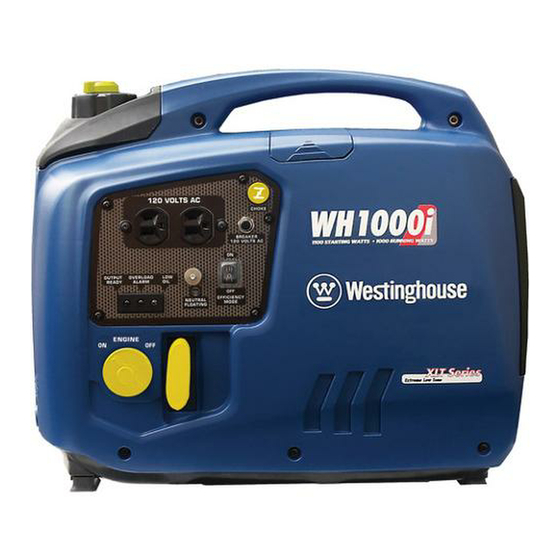
FEATURES GENERAL INVERTER FEATURES – WH1000i Figure 7 1 - Control Panel: Contains the reset breaker, 5 - Fuel Cap and Vent: Open the vent to run the outlets and warning lights. engine and close the vent when the engine is off. -
Page 18: Control Panel Features - Wh1000I
FEATURES CONTROL PANEL FEATURES – WH1000i Figure 8 – Control Panel Features 1 - 120-Volt, 20-Amp Duplex Outlet (NEMA 5 - Ground Terminal: The ground terminal is used 5-20R): The outlet is capable of carrying a to externally ground the inverter. -
Page 19: General Inverter Features - Wh2000I Series
FEATURES GENERAL INVERTER FEATURES – WH2000i SERIES Figure 9 1 - Control Panel: Contains the reset breaker, 6 - Engine Oil Fill/Drain Plug Service Panel: outlets and warning lights. Remove the panel to access the engine oil fill/ drain plug for maintenance. 2 - Choke Knob: Pull out to the ON position to start the engine, and push in to the OFF 7 - Air Cleaner Access Panel: Remove the panel... -
Page 20: Control Panel Features - Wh2000I Series
FEATURES CONTROL PANEL FEATURES – WH2000i SERIES Figure 10 – Control Panel Features 1 - 120-Volt, 20-Amp Duplex Outlet (NEMA 4 - Output Ready LED: The light will be green 5-20R): The outlet is capable of carrying a when the inverter is ready to be used. maximum of 20 amps. -
Page 21: General Inverter Features - Wh2000Ixlt
FEATURES GENERAL INVERTER FEATURES – WH2000iXLT Figure 11 1 - Control Panel: Contains the reset breaker, 6 - Engine Oil Fill/Drain Plug Service Panel: Remove the panel to access the engine oil fill/ outlets and warning lights. drain plug for maintenance. 2 - 12-Volt DC Power Socket: Provides 12-volt DC power up to 8 amps. -
Page 22: Control Panel Features - Wh2000Ixlt
FEATURES CONTROL PANEL FEATURES – WH2000iXLT Figure 12 – Control Panel Features 1 - 120-Volt, 20-Amp Duplex Outlet (NEMA 5 - Output Ready LED: The light will be green 5-20R): The outlet is capable of carrying a when the inverter is ready to be used. maximum of 20 amps. -
Page 23: Operation
OPERATION Weather – Never operate your inverter outdoors during BEFORE STARTING THE rain, snow or any combination of weather conditions INVERTER that could lead to moisture collecting on, in or around the inverter. Dry Surface – Always operate the inverter on a dry Before starting the inverter, review surface free of any moisture. -
Page 24: Inverter Paralleling Operation - Wh2000Ixlt Only
DANGER 1. Using only the Westinghouse paralleling cord (Part Never connect the paralleling cord to No. 260041) with both cord switches set to OFF (O), connect one male plug to one inverter and the inverters with the inverters running. -
Page 25: Initial Oil Fill
Figure 15 – Paralleling Cord Connected Figure 16 – WH1000i Engine Service Panel 6. To stop the inverters, unplug all connected loads, turn both cord switches to OFF (O) and unplug the 2. -
Page 26: Wh2000I Series
OPERATION 3. Using the supplied oil fill container and oil, fill the 6. Add the 100 ml of oil to the engine. The oil should container to the 2.0 mark on the container. Do not now be at the correct level (see Figure 20). - Page 27 OPERATION 2. Clean the area around the oil fill/drain plug and NOTICE remove plug (see Figure 22). Do not tilt the inverter to add oil. It must be filled on a flat, level surface. 4. Add the 200 ml of oil to the engine (see Figure 24).
-
Page 28: Adding / Checking Engine Fluids And Fuel
OPERATION Adding Gasoline to the Fuel Tank ADDING / CHECKING ENGINE FLUIDS AND FUEL WARNING Never refuel the inverter while the Before adding/checking engine engine is running. fluids and fuel, review Safety on page 7. Always turn the engine off and allow the inverter to cool before refueling. -
Page 29: Starting The Inverter
These key areas are highlighted in yellow. OTE: For the WH1000i, upon initial start-up or 1. Turn the fuel tank vent to the ON position (see when out of fuel, fill the inverter to the full Figure 27). -
Page 30: Using Efficiency Mode
1. To turn on the efficiency mode, press the switch to the ON position (see Figure 31). Figure 29 – Choke Knob (WH1000i Shown) 4. Firmly grasp and pull the recoil handle slowly until you feel increased resistance. At this point, apply a rapid pull while pulling out from the inverter (see Figure 30). -
Page 31: Stopping The Inverter
OPERATION STOPPING THE INVERTER Normal Operation During normal operation, use the following steps to stop your inverter: 1. Remove any connected loads from the control panel receptacles. 2. Allow the inverter to run at “no load” to reduce and stabilize engine and alternator temperatures. 3. -
Page 32: Maintenance
MAINTENANCE MAINTENANCE CAUTION Before performing maintenance Avoid skin contact with engine oil or on the inverter, review Safety on gasoline. Prolonged skin contact with page 7 and the following safety engine oil or gasoline can be harmful. messages. Frequent and prolonged contact with engine oil may cause skin cancer. -
Page 33: Engine Oil Maintenance
Figure 33 – Oil Fill/Drain Plug Figure 32 – Recommended Oil NOTICE Engine oil must always be checked and added when Checking Engine Oil – WH1000i the inverter is on a flat, level surface, or an inaccurate reading may result, causing serious engine damage. NOTICE 7. -
Page 34: Checking Engine Oil - Wh2000I Series
If oil level is low, add to the correct level using 9. Continue to add oil until the oil is at the correct the supplied oil fill bottle. Do not overfill the oil level. See Checking Engine Oil – WH1000i on page crankcase. -
Page 35: Adding Engine Oil - Wh2000I Series
Figure 39 – Draining Engine Oil 7. Allow oil to completely drain. 8. Fill crankcase with oil following the steps outlined in Adding Engine Oil – WH1000i on page 35. NOTICE Figure 38 – Adding Engine Oil Never dispose of used engine oil by dumping the 9. -
Page 36: Changing Engine Oil - Wh2000I Series
filter. 4. Place oil pan (or suitable container) under the oil fill/ drain plug. Cleaning the Air Filter – WH1000i 5. With a damp rag, thoroughly clean around the oil fill/drain plug. The air filter must be cleaned after every 50 hours of use or 3 months (frequency should be increased if 6. -
Page 37: Cleaning The Air Filter - Wh2000I Series
MAINTENANCE Cleaning the Air Filter – WH2000i Series The air filter must be cleaned after every 50 hours of use or 3 months (frequency should be increased if inverter is operated in a dusty environment). 1. Turn off the inverter and let it cool for several minutes if running. -
Page 38: Draining The Float Bowl
5. Wash the foam air filter element by submerging DRAINING THE FLOAT BOWL the element in a solution of household detergent soap and warm water. Slowly squeeze the foam to WH1000i thoroughly clean. 1. Remove the engine service panel to access the NOTICE carburetor. -
Page 39: Wh2000I Series
3. Loosen the float bowl drain screw until fuel is seen draining from the float bowl (see Figure 47). Figure 48 – Spark Plug Access Cover (WH1000i Shown) 4. Remove the spark plug boot by firmly pulling the plastic spark plug boot handle directly away from the engine (see Figure 49). - Page 40 Figure 49 – Removal of Spark Plug Boot (WH1000i Shown) Figure 51 – Spark Plug Gap Requirements 5. Clean area around the spark plug. 8. Install the spark plug by carefully following the steps 6.
-
Page 41: Cleaning The Spark Arrestor
MAINTENANCE 6. Pull the spark arrestor screen off the muffler CLEANING THE SPARK exhaust pipe. ARRESTOR 7. Using a wire brush, remove any dirt and debris that may have collected on the spark arrestor screen. Check and clean the spark arrestor after every 100 hours of use or 6 months. - Page 42 MAINTENANCE 5. Change the oil (see Changing Engine Oil – WH1000i on page 35) or Changing Engine Oil – WH2000i Series on page 36). 6. Remove the spark plug (see Spark Plug Maintenance on page 39) and place about 1 tablespoon of oil in the spark plug opening.
- Page 43 MAINTENANCE This Page Intentionally Left Blank...
-
Page 44: Service Parts
MAINTENANCE SERVICE PARTS WH1000i Service Parts 9 10 Figure 54... - Page 45 MAINTENANCE Item WPP# Description 260028 Fuel Strainer 260007 Fuel Tank Cap Assy. 260002 Spark Plug Cover 260003 A5RTC (Torch) Spark Plug 260006 Choke Cable 260005 Reset Breaker 260014 Efficiency Mode Switch 260004 Recoil Starter 260001 Maintenance Door 260000 Air Cleaner Element 260015 Oil Filler Plug 260012...
-
Page 46: Wh2000I Series Service Parts
MAINTENANCE WH2000i Series Service Parts 21 22 24 25 Figure 55... - Page 47 MAINTENANCE Item WPP# Description 260027 Indicator Lights 260005 Reset Breaker 260014 Efficiency Mode Switch 260021 Choke Cable 260039 12-volt DC Power Socket – WH2000iXLT Model 260020 Recoil Starter 260019 Spark Plug Cover 260003 A5RTC (Torch) Spark Plug 260017 Oil Filling Cover 260015 Oil Filler Plug 260018...
-
Page 48: Troubleshooting
Stale fuel Drain fuel and replace with fresh fuel. 10. Fuel system needs priming 10. Prime the fuel system (see page 29). (WH1000i) Inverter is out of fuel. Check fuel level (see page 28). Add fuel if necessary. Inverter suddenly stops... - Page 49 MANUAL DEL PROPIETARIO...
- Page 50 California California Proposition 65 Warning Proposition 65 Warning The engine exhaust from this product Certain components in this product and its contains chemicals known to the state of related accessories contain chemicals California to cause cancer, birth defects known to the state of California to cause or other reproductive harm.
-
Page 51: Felicitaciones Por Adquirir Un Inversor Westinghouse
Recibo de compra: (conserve el recibo de compra para asegurar la cobertura sin problemas de la garantía). Registro del producto: Para asegurar la cobertura sin problemas de la garantía es importante que registre el inversor Westinghouse. Puede registrarlo haciendo lo siguiente: 1. - Page 53 MANTENIMIENTO DEL ACEITE DEL MOTOR ....................33 Especificación del aceite del motor ......................33 Procedimiento para controlar el aceite del motor – WH1000i ..............33 Procedimiento para controlar el aceite del motor – Serie WH2000i ............34 Procedimiento para agregar el aceite del motor – WH1000i ..............34 Procedimiento para agregar el aceite del motor –...
- Page 54 ÍNDICE ALMACENAMIENTO ............................41 PIEZAS DE SERVICIO .............................42 Piezas de servicio del modelo WH1000i ....................42 Piezas de servicio de la serie WH2000i .....................44 SOLUCIÓN DE PROBLEMAS ..........................46 SOLUCIÓN DE PROBLEMAS .........................46...
-
Page 55: Seguridad
SEGURIDAD DEFINICIONES DE DEFINICIONES DE LOS SEGURIDAD SÍMBOLOS DE SEGURIDAD Las palabras PELIGRO, ADVERTENCIA, Símbolo Descripción PRECAUCIÓN y AVISO se usan a lo largo de este manual para destacar la información importante. Asegúrese de que todo aquel que trabaje con el equipo Símbolo de alerta de seguridad o cerca de él conozca el significado de estas alertas. -
Page 56: Normas Generales De Seguridad
SEGURIDAD NORMAS GENERALES DE ADVERTENCIA SEGURIDAD La gasolina y los vapores de la gasolina son extremadamente inflamables PELIGRO y explosivos en determinadas condiciones. Nunca use el inversor en lugares • Siempre debe hacer la recarga mojados o húmedos. Nunca exponga de combustible del inversor en el inversor a lluvia, nieve, rociado de exteriores, en una zona bien... - Page 57 SEGURIDAD ADVERTENCIA Nunca opere el inversor si se sobrecalientan los componentes eléctricos, si cae la salida de energía eléctrica, si salen chispas, llamas o humo del inversor, o si los receptáculos están dañados. Nunca use el inversor para alimentar equipos de asistencia médica. Siempre retire del inversor las herramientas u otros equipos de servicio que se utilicen durante el...
-
Page 58: Etiquetas Y Calcomanías De Seguridad - Wh1000I
SEGURIDAD ETIQUETAS Y CALCOMANÍAS DE SEGURIDAD – WH1000i BACK FRONT Figura 1... - Page 59 SEGURIDAD Figura 2...
-
Page 60: Etiquetas Y Calcomanías De Seguridad - Serie Wh2000I
SEGURIDAD ETIQUETAS Y CALCOMANÍAS DE SEGURIDAD – SERIE WH2000i BACK FRONT Figura 3... - Page 61 SEGURIDAD Figura 4...
-
Page 62: Etiquetas Y Calcomanías De Seguridad - Wh2000Ixlt
SEGURIDAD ETIQUETAS Y CALCOMANÍAS DE SEGURIDAD – WH2000iXLT BACK FRONT Figura 5... - Page 63 SEGURIDAD Figura 6...
-
Page 64: Desembalar
DESEMBALAR PROCEDIMIENTO PARA DESEMBALAR EL INVERSOR PRECAUCIÓN Siempre debe solicitar ayuda para levantar el inversor. El inversor es pesado, levantarlo puede causarle lesiones físicas. Evite cortar sobre o cerca de grapas para evitar lesiones personales. Herramientas requeridas: trincheta o dispositivo similar. -
Page 65: Características
CARACTERÍSTICAS CARACTERÍSTICAS GENERALES DEL INVERSOR – WH1000i Figura 7 1 - Tablero de control: Contiene el disyuntor 5 - Tapa y ventilación del combustible: Abra la de reinicio, los tomacorrientes y las luces de ventilación para hacer andar el motor y cierre la advertencia. -
Page 66: Características Del Tablero De Control - Wh1000I
CARACTERÍSTICAS CARACTERÍSTICAS DEL TABLERO DE CONTROL – WH1000i Figura 8 – Características del tablero de control 1 - Tomacorrientes de 120 Voltios, 20 5 - Terminal de tierra: El terminal de tierra se usa Amperios Dúplex (NEMA 5-20R): El para conectar el inversor a tierra externamente. -
Page 67: Características Generales Del Inversor - Serie Wh2000I
CARACTERÍSTICAS CARACTERÍSTICAS GENERALES DEL INVERSOR – SERIE WH2000i Figura 9 Tablero de control: Contiene el disyuntor de reinicio, los Tablero de servicio del tapón de llenado/drenaje de tomacorrientes y las luces de advertencia. aceite del motor: Extraiga el tablero para acceder al tapón de llenado/drenaje de aceite del motor para el Perilla de cebado: Jale hacia afuera hasta la posición mantenimiento. -
Page 68: Características Del Tablero De Control - Serie Wh2000I
CARACTERÍSTICAS CARACTERÍSTICAS DEL TABLERO DE CONTROL – SERIE WH2000i Figura 10 – Características del tablero de control 1 - Tomacorrientes de 120 Voltios, 20 4 - LED de salida lista: La luz será de color Amperios Duplex (NEMA 5-20R): El verde cuando el inversor esté... -
Page 69: Características Generales Del Inversor - Wh2000Ixlt
CARACTERÍSTICAS CARACTERÍSTICAS GENERALES DEL INVERSOR – WH2000iXLT Figura 11 Tablero de control: Contiene el disyuntor de reinicio, los Tablero de servicio del tapón de llenado/drenaje de tomacorrientes y las luces de advertencia. aceite del motor: Extraiga el tablero para acceder al tapón de llenado/drenaje de aceite del motor para el Tomacorriente de 12 voltios DC: Brinda energía mantenimiento. -
Page 70: Características Del Tablero De Control - Wh2000Ixlt
CARACTERÍSTICAS CARACTERÍSTICAS DEL TABLERO DE CONTROL – WH2000iXLT Figura 12 – Características del tablero de control 1 - Tomacorrientes de 120 Voltios, 20 5 - LED de salida lista: La luz será de color Amperios Duplex (NEMA 5-20R): El verde cuando el inversor esté listo para su tomacorrientes tiene capacidad de suministrar uso. -
Page 71: Funcionamiento
FUNCIONAMIENTO No debe haber cargas conectadas: Compruebe ANTES DE ARRANCAR EL que el inversor no tenga cargas conectadas antes INVERSOR de encenderlo. Para asegurar que no haya cargas conectadas, desenchufe los prolongadores eléctricos que estén enchufados en los receptáculos del tablero de control. -
Page 72: Operación Paralela Con Conversores - Wh2000Ixlt Sólo
PELIGRO 1. Usando únicamente el cable paralelo Westinghouse No conecte el cable paralelo a los (Parte No. 260041) y siempre que ambos conversores cuando los conversores interruptores del cable estén apagados (O), conecte están funcionando. -
Page 73: Llenado De Aceite Inicial
5. Cuando haya electricidad, se iluminará una luz en el enchufe de tres clavijas que está conectado al inversor. Figura 16 – Tablero de servicio del motor WH1000i Limpie la zona que rodea el tapón de llenado/drenaje de aceite y extraiga el tapón (Vea Figura 17). -
Page 74: Serie Wh2000I
FUNCIONAMIENTO OTA: La capacidad de aceite para el 1000i es de Llene el recipiente con aceite nuevamente sólo hasta 400 ml. la marca correspondiente a 1.0. Mediante el uso del recipiente de llenado de aceite 6. Agregue los 100 ml de aceite al motor. Ahora, el y el aceite suministrados, llene el recipiente hasta la aceite debe estar en el nivel correcto (Vea Figura... - Page 75 FUNCIONAMIENTO 2. Limpie la zona que rodea el tapón de llenado/ Agregue los 200 ml de aceite al motor (Vea Figura drenaje de aceite y extraiga el tapón (Vea Figura 24). 22). Figura 22 – Tapón de llenado/drenaje de aceite Figura 24 –...
-
Page 76: Procedimiento Para Agregar/Controlar El Combustible Y Los Líquidos Del Motor
FUNCIONAMIENTO Procedimiento para agregar gasolina al PROCEDIMIENTO PARA depósito de combustible AGREGAR/CONTROLAR EL COMBUSTIBLE Y LOS ADVERTENCIA LÍQUIDOS DEL MOTOR Nunca haga la recarga de combustible del inversor mientras el motor está en marcha. Antes de agregar/controlar el combustible y los líquidos del motor, revise Seguridad en la página 7. -
Page 77: Arranque Del Inversor
Gire la ventilación del depósito de combustible hasta OTA: Para el modelo WH1000i, al momento del la posición ON (encendido) (Vea Figura 27). arranque inicial o cuando se termina el combustible, cargue el inversor hasta el nivel máximo. -
Page 78: Uso Del Modo De Eficiencia
En ese punto, aplique un tirón rápido mientras tira alejándola del inversor (Vea Figura 30). Figura 31 – Interruptor de modo de eficiencia (se muestra el modelo WH1000i) 2. Si no hay ninguna carga, las RPM del inversor se reducen hasta una velocidad de ralentí. -
Page 79: Restablecimiento Del Disyuntor
FUNCIONAMIENTO Restablecimiento del disyuntor de reinicio El inversor activa el disyuntor y se desconecta automáticamente de la carga cuando los controles detectan una condición de sobrecarga predeterminada. El motor del inversor continúa en funcionamiento pero no habrá ninguna salida eléctrica. 1. -
Page 80: Mantenimiento
MANTENIMIENTO MANTENIMIENTO PRECAUCIÓN Antes de realizar tareas de Evite que la piel esté en contacto con el mantenimiento del inversor, analice aceite del motor o la gasolina. El contacto Seguridad en la página 7 y los prolongado de la piel con el aceite del siguientes mensajes de seguridad. -
Page 81: Mantenimiento Del Aceite Del Motor
Figura 32 – Aceite recomendado nivelada, o se puede obtener una lectura inadecuada, Procedimiento para controlar el aceite causando daños graves al motor. del motor – WH1000i Controle el nivel de aceite: Al controlar el aceite del motor, extraiga el tapón de AVISO llenado/drenaje de aceite. -
Page 82: Procedimiento Para Controlar El Aceite Del Motor - Serie Wh2000I
Procedimiento para agregar el aceite Deje que el motor quede inactivo y se enfríe durante varios minutos (deje que la presión del cárter se del motor – WH1000i equilibre). Siempre opere o mantenga el inversor sobre una Extraiga el tablero de servicio del motor para acceder superficie plana. -
Page 83: Procedimiento Para Agregar El Aceite Del Motor - Serie Wh2000I
Vea Procedimiento para controlar el aceite del que rodea al tapón de llenado/drenaje de aceite. motor – WH1000i en la página 33. Incline el inversor de manera que el aceite se drene por la canaleta al interior del recipiente (Vea Figura 39). -
Page 84: Mantenimiento Del Filtro De Aire
filtro de aire. Lave el elemento de espuma del filtro de aire sumergiéndolo en una solución de detergente para el Limpieza del filtro de aire – WH1000i hogar y agua caliente. Apriete lentamente la espuma hasta que quede completamente limpia. -
Page 85: Limpieza Del Filtro De Aire - Serie Wh2000I
MANTENIMIENTO Enjuáguela en agua limpia sumergiendo el elemento del filtro de aire en agua dulce y apretándolo lentamente. AVISO Nunca deseche la solución jabonosa usada para limpiar el filtro de aire arrojándola en un desagüe, en la tierra o en aguas subterráneas o vías fluviales. Siempre debe ser responsable con el medio ambiente. -
Page 86: Drenaje De La Cubeta De Flotación
DRENAJE DE LA CUBETA DE FLOTACIÓN Extraiga el tablero de servicio del motor para acceder al drenaje de la cubeta de flotación. WH1000i Extraiga el tablero de servicio del motor para acceder al carburador. Ubique la manguera plástica transparente de flotación que sale de la base del inversor y coloque un recipiente adecuado debajo para juntar el combustible drenado. -
Page 87: Mantenimiento De Bujía
(Vea Figura 48). Figura 49 – Procedimiento para retirar el capuchón de la bujía de encendido (se muestra el modelo WH1000i) 5. Limpie la zona que rodea a la bujía de encendido. 6. Mediante el uso de la llave de cubo de la bujía suministrada, extraiga la bujía de la tapa de cilindro... -
Page 88: Limpieza Del Amortiguador De Chispas
MANTENIMIENTO 8. Inspeccione la bujía de encendido para detectar: LIMPIEZA DEL Si el aislador está agrietado o astillado. AMORTIGUADOR DE CHISPAS Si está excesivamente desgastada Controle y limpie el amortiguador de chispas después de 100 La separación de la bujía es de 0,032 pulgada horas de uso o cada 6 meses. -
Page 89: Limpieza Del Inversor
5. Cambie el aceite (Vea Procedimiento para controlar Coloque la abrazadera de banda del el aceite del motor – WH1000i en la página 33 o amortiguador de chispas sobre la pantalla y Procedimiento para controlar el aceite del motor –... -
Page 90: Piezas De Servicio
MANTENIMIENTO PIEZAS DE SERVICIO Piezas de servicio del modelo WH1000i 9 10 Figura 54... - Page 91 MANTENIMIENTO Artículo WPP# Descripción Cantidad 260028 Filtro de combustible 260007 Conjunto de tapa de depósito de combustible 260002 Cubierta de bujía 260003 Bujía A5RTC (Torch) 260006 Cable de cebado 260005 Disyuntor de reinicio 260014 Interruptor de modo de eficiencia 260004 Arrancador de retroceso 260001 Puerta de mantenimiento...
-
Page 92: Piezas De Servicio De La Serie Wh2000I
MANTENIMIENTO Piezas de servicio de la serie WH2000i 21 22 24 25 Figura 55... - Page 93 MANTENIMIENTO Artículo WPP# Descripción Cantidad 260027 Luces indicadoras 260005 Disyuntor de reinicio 260014 Interruptor de modo de eficiencia 260021 Cable de cebado 260039 Tomacorriente de 12 voltios DC – WH2000iXLT 260020 Arrancador de retroceso 260019 Cubierta de bujía 260003 Bujía A5RTC (Torch) 260017 Cubierta de llenado de aceite 260015...
-
Page 94: Solución De Problemas
Drene combustible y sustituya con combustible fresco. 10. El sistema de combustible necesita 10. Cebe el sistema de combustible (Vea la página 29). cebado (WH1000i) El inversor se queda sin combustible. Verifique el nivel de combustible (Vea la página 28). Agregue combustible si es necesario.
Need help?
Do you have a question about the WH1000i and is the answer not in the manual?
Questions and answers