Planet GSD-802S User Manual
8-port gigabit websmart ethernet and poe
Hide thumbs
Also See for GSD-802S:
- User manual (87 pages) ,
- Quick installation manual (2 pages) ,
- User manual (20 pages)

Related Manuals for Planet GSD-802S


Summary of Contents for Planet GSD-802S
- Page 1 User's Manual GSD-802S 8-Port Gigabit Web Smart Ethernet Switch GSD-802PS 8-Port Gigabit Web Smart PoE Switch...
- Page 2 PLANET has made every effort to ensure that this User's Manual is accurate; PLANET disclaims liability for any inaccuracies or omissions that may have occurred.
-
Page 3: Table Of Contents
User’s Manual of GSD-802S / GSD-802PS TABLE OF CONTENTS 1. INTRODUCTION................................1 1.1 P ..............................1 ACKAGE ONTENTS 1.2 H ............................1 OW TO ANUAL 1.3 P ..............................1 RODUCT EATURES 1.4 PRODUCT SPECIFICATION............................. 1 2. INSTALLATION................................3 2.1 P .............................. - Page 4 User’s Manual of GSD-802S / GSD-802PS 4.9.1 IGMP Snooping Configuration..........................2 4.10 Q ..............................4 UALITY OF ERVICE 4.10.1 802.1p QoS Mode ............................. 5 4.10.2 DSCP QoS Mode .............................. 6 4.11 802.1X M ..............................8 ANAGEMENT 4.11.1 802.1X Configuration ............................9 4.11.2 802.1X Parameters ............................
- Page 5 User’s Manual of GSD-802S / GSD-802PS 7. TROUBLESHOOTING..............................5 APPENDIX A ..................................6 A.1 S ‘ RJ-45 P ..........................6 WITCH SSIGNMENTS A.2 10/100M , 10/100B -TX ............................ 6 A.3 RJ-45 ............................7 CABLE PIN ASSIGNMENT...
-
Page 6: Introduction
User’s Manual of GSD-802S / GSD-802PS 1. INTRODUCTION 1.1 Package Contents Check the contents of your package for following parts: Web Smart Gigabit Ethernet Switch x1 ● User's Manual CD x1 ● Quick Installation Guide x1 ● Power Cord x1 ●... -
Page 7: Product Features
User’s Manual of GSD-802S / GSD-802PS 1.3 Product Features Physical Port GSD-802S 8-Port 10/100/1000Base-T RJ-45 Copper with 2 Shared SFP / mini-GBIC slots GSD-802PS 8-Port 10/100/1000Base-T RJ-45 Copper with 2 Shared SFP / mini-GBIC slots Generic Features Comply with IEEE 802.3, 10Base-T, IEEE 802.3u, 100Base-TX, IEEE 802.3ab,1000Base-T, IEEE 802.3z,1000Base-SX/LX, Ethernet standard... -
Page 8: Product Specification
User’s Manual of GSD-802S / GSD-802PS Management Remote Web management interface Firmware upgrade through web interface Cable Diagnostics technology Support SNMPv1 with RFC-1213/1573-Interface group, Ethernet MIB SNMP Trap 1.4 PRODUCT SPECIFICATION Model GSD-802S GSD-802PS Hardware Specification 8-Port 10/100/1000Base-T Auto MDI/MDI-X... - Page 9 User’s Manual of GSD-802S / GSD-802PS IEEE 802.3 Ethernet IEEE 802.3u Fast Ethernet IEEE 802.3ab Gigabit Ethernet, 1000Base-T IEEE 802.3z Gigabit Ethernet, 1000Base-SX/LX IEEE 802.1Q Tagged VLAN Network Standards IEEE 802.1w Rapid Spanning Tree IEEE 802.1X Port-Based Authentication IEEE 802.3ad Link Aggregation Control Protocol IEEE 802.3x...
-
Page 10: Installation
Gigabit environment. 2.1.1 Product Overview PLANET Gigabit Ethernet Switch is a Web Smart Gigabit Ethernet Switch with 8 RJ-45 10/100/1000Mbps ports for high-speed network connectivity. The Gigabit Ethernet Switch can also automatically identify and determine the correct transmission speed and half/full duplex mode of the attached devices with its 8 ports. -
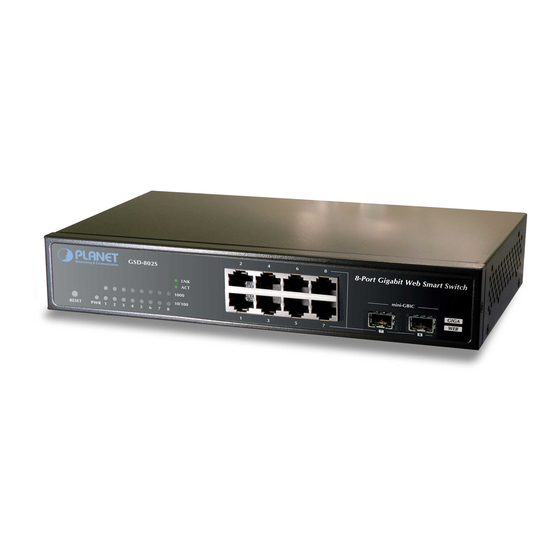
Page 11: Switch Front Panel
User’s Manual of GSD-802S / GSD-802PS 2.1.2 Switch Front Panel Figure 2-1 & Figure 2-2 shows a front panel of GSD-802S and GSD-802PS. Figure 2-1 PLANET GSD-802S Front Panel Figure 2-2 PLANET GSD-802PS Front Panel 2.1.3 LED Indicators LED of GSD-802S ■... -
Page 12: Switch Rear Panel
User’s Manual of GSD-802S / GSD-802PS Figure 2-4 PLANET GSD-802PS LED panel 2.1.4 Switch Rear Panel The rear panel of the Gigabit Ethernet Switch indicates an AC inlet power socket, which accepts input power from 100 to 240VAC, 50-60Hz. Figure 2-5 Rear Panel of GSD-802S... -
Page 13: Install The Switch
User’s Manual of GSD-802S / GSD-802PS 2.2 Install the Switch This section describes how to install your Gigabit Ethernet Switch and make connections to the Switch. Please read the following topics and perform the procedures in the order being presented. To install your Gigabit Ethernet Switch on a desktop or shelf, simply complete the following steps. -
Page 14: Rack Mounting
User’s Manual of GSD-802S / GSD-802PS 2.2.2 Rack Mounting To install the Gigabit Ethernet Switch in a 19-inch standard rack, please follows the instructions described below. Step1: Place the Gigabit Ethernet Switch on a hard flat surface, with the front panel positioned towards the front side. -
Page 15: Installing The Sfp Transceiver
Figure 2-9 Plug-in the SFP Transceiver Approved PLANET SFP Transceivers PLANET Gigabit Ethernet Switch supports both single mode and multi mode SFP transceiver. The following list of approved PLANET SFP transceivers is correct at the time of publication: ■MGB-SX SFP (1000Base-SX SFP transceiver ) ■MGB-LX SFP (1000Base-LX SFP transceiver ) - Page 16 User’s Manual of GSD-802S / GSD-802PS Check the Link mode of the SFP port if the link failed. Co works with some fiber-NICs or Media Converters, set the Link mode to “1000 Force” is needed. Remove the transceiver module Make sure there is no network activity by consult or check with the network administrator. Or through the management interface of the switch/converter (if available) to disable the port in advance.
-
Page 17: Switch Management
User’s Manual of GSD-802S / GSD-802PS 3. SWITCH MANAGEMENT This chapter describes how to manage the Gigabit Ethernet Switch. Topics include: - Overview - Management methods - Assigning an IP address to the Gigabit Ethernet Switch - Logging on to the Gigabit Ethernet Switch 3.1 Overview... -
Page 18: Management Methods
- Web Management via a network or dial-up connection. 3.2.1 Web Management The PLANET Gigabit Ethernet Switch provides a built-in browser interface. You can manage the Gigabit Ethernet Switch remotely by having a remote host with web browser, such as Microsoft Internet Explorer, Netscape Navigator or Mozilla Firefox. - Page 19 User’s Manual of GSD-802S / GSD-802PS Figure 3-1 Web Login Screen of Gigabit Ethernet Switch For security reason, please change and memorize the new password after this first setup. Only accept command in lowercase letter under web interface.
-
Page 20: Configuration
Gigabit Ethernet Switch from the local LAN. This section indicates how to configure the Gigabit Ethernet Switch to enable its smart function. The following section will base on the web screens of GSD-802PS, for GSD-802S the display will be the same to GSD-802PS. - Page 21 User’s Manual of GSD-802S / GSD-802PS Main Menu Using the onboard web agent, you can define system parameters, manage and control the Web Smart Switch, and all its ports, or monitor network conditions. Via the Web-Management, the administrator can setup the Web Smart Switch by select the functions those listed in the Main Function.
-
Page 22: System
User’s Manual of GSD-802S / GSD-802PS 4.2 System 4.2.1 System Info The System Info page provides information for the current device information. System Info page helps a switch administrator to identify the firmware / hardware version and IP subnet address / DHCP server IP address. The screen in Figure 4-2-1 appears. -
Page 23: Misc Configuration
User’s Manual of GSD-802S / GSD-802PS 4.2.2 Misc Configuration The Misc Configuration includes the System name, Location name, Login Timeout, IP Address, Subnet Mask and Gateway. Through the Web Smart Switch Utility, you can easily recognize the device by using the System Name and the Location Name. - Page 24 User’s Manual of GSD-802S / GSD-802PS of the switch. Defines the user-defined device name. System Name Defines the user-defined device description. System Description This function provides administrator to secure Web login. Password Specifies a time period for the user login. The web interface will be auto logout if Inactivity Timeout there’re no actions from the login user.
-
Page 25: Port Configuration
User’s Manual of GSD-802S / GSD-802PS 4.3 Port Configuration This function allows displaying each port’s status. The Link Status in the screen displays the current connection speed and duplex mode; else this function will show down when the port is disconnected. Press the “Refresh” button to renew the screen. - Page 26 User’s Manual of GSD-802S / GSD-802PS • 1000 full - Force sets 10000Mbps/Full-Duplex mode. • Disable - Shutdown the port manually. • Flow Control Allow Enable or Disable flow control for selected port. • Enable – 802.3x flow control is enabled on Full-Duplex mode or Backpressure is enabled on Half-Duplex mode.
-
Page 27: Port Mirroring
Configuring the port mirroring by assigning a source port from which to copy all packets and a destination port where those packets will be sent. With the Chipset specification – the GSD-802S/GSD-802PS port mirroring support RX (receive) mode only - this mode will duplicate the data that send to the source and forward to the destination... -
Page 28: Storm Control
User’s Manual of GSD-802S / GSD-802PS 4.5 Storm Control Storm control for the Gigabit Ethernet Switch is configured on this page. There three types of storm rate control: Unicast storm rate control Multicast storm rate control Broadcast storm rate control. -
Page 29: Vlans
User’s Manual of GSD-802S / GSD-802PS 4.6 VLANs A Virtual LAN (VLAN) is a logical network grouping that limits the broadcast domain. It allows you to isolate network traffic so only members of the VLAN receive traffic from the same VLAN members. Basically, creating a VLAN from a switch is logically equivalent of reconnecting a group of network devices to another Layer 2 switch. -
Page 30: Vlan Membership
User’s Manual of GSD-802S / GSD-802PS 4.6.1 VLAN Membership This function group individual ports into a small “Virtual” network of their own to be independent of the other ports. The screen in Figure 4-6-1 appears. Figure 4-6-1 Port Segmentation (VLAN) Configuration Screen... - Page 31 User’s Manual of GSD-802S / GSD-802PS As show in Figure 4-6-2 & Figure 4-6-3 Figure 4-6-2 Add a VLAN Screen Figure 4-6-3 VLAN Member Setup Screen 4.6.1.2 Modify the VLAN Group Member Once you want to modify the existence VLAN Group member or delete a existence VLAN Group. Refer to the following steps.
-
Page 32: Per Port Configuration
User’s Manual of GSD-802S / GSD-802PS As show in Figure 4-6-4 appears. Figure 4-6-4 VLAN Group – Member Modify And Delete VLAN Group Screen Once the VLAN Group be deleted, the Ports with the PVID set to this VLAN Group have to re-configure the PVID. - Page 33 User’s Manual of GSD-802S / GSD-802PS The page includes the following fields: Object Description • VLAN Type There’re two VLAN mode support – 802.1Q VLAN and Port-based VLAN • 802.1Q – Packets income will be tagged with VID as the PVID setting. All ports on the switch belong to default VLAN (VID 1).
-
Page 34: Vlan Setting Example
User’s Manual of GSD-802S / GSD-802PS 4.6.3 VLAN setting example: 4.6.3.1 Two separate 802.1Q VLAN The diagram shows how the switch handle Tagged and Untagged traffic flow for two VLANs. VLAN Group 2 and VLAN Group 3 are separated VLAN. Each VLAN isolate network traffic so only members of the VLAN receive traffic from the same VLAN members. - Page 35 User’s Manual of GSD-802S / GSD-802PS Untagged packet entering VLAN 3 While [PC-4] transmit an untagged packet enters Port-4, the switch will tag it with a VLAN Tag=3. [PC-5] and [PC-6] will received the packet through Port-5 and Port-6. While the packet leaves Port-5, it will be stripped away it tag becoming an untagged packet.
- Page 36 User’s Manual of GSD-802S / GSD-802PS Figure 4-6-8 Assign VLAN Members For VLAN 2 and VLAN 3 Remember to remove the Port 1 – Port 6 from VLAN 1 membership, since the Port 1 – Port 6 had been assigned to VLAN 2 and VLAN 3.
- Page 37 User’s Manual of GSD-802S / GSD-802PS It’s import to remove the VLAN members from VLAN 1 configuration. Or the ports would become overlap setting. ( About the overlapped VLAN configuration, see next VLAN configure sample) Assign PVID for each port:...
- Page 38 User’s Manual of GSD-802S / GSD-802PS 4.6.3.2 Two VLANs with overlap area Follow the example of 4.6.3.1. There’re two exist separate VLANs – VLAN 2 and VLAN 3, and the PCs of each VLANs are not able to access each other of different VLANs. But they all need to access with the same server. The screen in Figure 4-16 appear.
- Page 39 User’s Manual of GSD-802S / GSD-802PS Define a VLAN 1 as a “Public Area” that overlapping with both VLAN 2 members and VLAN 3 members. Figure 4-6-13 VLAN 1 – The Public Area Member Assign Setup Port-7 with “PVID=1” at VLAN per Port Configuration page. The screen in Figure 4-6-14 appears.
- Page 40 User’s Manual of GSD-802S / GSD-802PS That is, although the VLAN 2 members: Port-1 to Port-3 and VLAN 3 members: Port-4 to Port-6 also belong to VLAN 1. But with different PVID settings, packets form VLAN 2 or VLAN 3 is not able to access to the other VLAN.
- Page 41 User’s Manual of GSD-802S / GSD-802PS Assign the VLAN Trunk Port to be the member of each VLAN – which wants to be aggregated. At this sample, add Port-8 to be VLAN 2 and VLAN 3 member port. Figure 4-6-17 Add VLAN Trunk Port To Each VLAN Repeat Step 1 and 2, setup the VLAN Trunk port at the partner switch.
-
Page 42: Rapid Spanning Tree
User’s Manual of GSD-802S / GSD-802PS 4.7 Rapid Spanning Tree Spanning Tree Protocol (STP) provides tree topography for any arrangement of bridges. STP also provides one path between end stations on a network, eliminating loops. Rapid Spanning Tree Protocol (RSTP) - While Classic Spanning Tree guarantees preventing L2 forwarding loops in a general network topology, convergence can take up to 30-60 seconds. -
Page 43: Rstp System Configuration
User’s Manual of GSD-802S / GSD-802PS Figure 4-7-1 Rappid Spanning Tree System/Port Configuration 4.7.1 RSTP System Configuration The “RSTP System Configuration” table allows configuring the spanning tree parameters. Figure 4-7-2 RSTP System Configuration... - Page 44 User’s Manual of GSD-802S / GSD-802PS The page includes the following fields: Object Description • System Priority Specifies the bridge priority value. When switches or bridges are running STP, each is assigned a priority. After exchanging BPDUs, the switch with the lowest priority value becomes the Root Bridge.
-
Page 45: Rstp Port Configuration
User’s Manual of GSD-802S / GSD-802PS 4.7.2 RSTP Port Configuration The RSTP Port Configuration page contains fields for assigning RSTP properties to individual ports. The screen in Figure 4-7-3 appears. Figure 4-7-3 RSTP Port Configuration The page includes the following fields:... -
Page 46: Link Aggregation
User’s Manual of GSD-802S / GSD-802PS 4.8 Link Aggregation Port Aggregation optimizes port usage by linking a group of ports together to form a single Link Aggregated Groups (LAGs). Port Aggregation multiplies the bandwidth between the devices, increases port flexibility, and provides link redundancy. -
Page 47: Lacp
User’s Manual of GSD-802S / GSD-802PS The page includes the following fields: Object Description • Port Indicate port 1 to port 8. • Normal While a port is checked as “Normal”, the port is not joining to any Static Trunk Group. - Page 48 User’s Manual of GSD-802S / GSD-802PS The page includes the following fields: Object Description • Port Indicate port 1 to port 8. • Protocol Enable To Enable or disable the LCAP protocol on a selected port. Once the LACP protocol be enabled, the system will start transmit the LACP control packets and exchange with another LACP aware switch.
-
Page 49: Igmp Snooping
User’s Manual of GSD-802S / GSD-802PS 4.9 IGMP Snooping The Internet Group Management Protocol (IGMP) lets host and routers share information about multicast groups memberships. IGMP snooping is a switch feature that monitors the exchange of IGMP messages and copies them to the CPU for feature processing. - Page 50 User’s Manual of GSD-802S / GSD-802PS elected as the ‘queried’. This router then keeps track of the membership of the multicast groups that have active members. The information received from IGMP is then used to determine if multicast packets should be forwarded to a given sub network or not.
-
Page 51: Quality Of Service
802.1p Mode –The output queue assignment is determined by the IEEE802.1p VLAN priority tag. DSCP Mode - The output queue assignment is determined by the DSCP field. The current version of GSD-800S/GSD-802S/GSD-802PS support QoS Strict mode only. The strict mode is to specifies if traffic scheduling is based strictly on the queue priority. -
Page 52: 802.1P Qos Mode
User’s Manual of GSD-802S / GSD-802PS 4.10.1 802.1p QoS Mode QoS settings allow customization of packet priority in order to facilitate delivery of data traffic that might be affected by latency problems. The IEEE 802.1p Priority specification uses 8 priority levels to classify data packets. The screen in Figure 4-10-2 appears. -
Page 53: Dscp Qos Mode
User’s Manual of GSD-802S / GSD-802PS 4.10.2 DSCP QoS Mode DiffServ Code Point (DSCP) - is the traffic prioritization bits within an IP header that are encoded by certain applications and/or devices to indicate the level of service required by the packet across a network. - Page 54 User’s Manual of GSD-802S / GSD-802PS • Low = Queue 0 • Normal = Queue 1 • Medium = Queue 2 • High = Queue 3...
-
Page 55: 802.1X Management
User’s Manual of GSD-802S / GSD-802PS 4.11 802.1X Management The PLANET Gigabit Ethernet Switch supports IEEE 802.1X Port-base network access control and RADIUS server authentication to enhance the host link more security. An 802.1X Infrastructure is composed of three major components: Authenticator, Authentication server, and Supplicant. - Page 56 User’s Manual of GSD-802S / GSD-802PS The client and RADIUS server derive encryption keys. The RADIUS server sends Web-Smart Switch a RADIUS ACCEPT message. 10. Web-Smart Switch sends the client an EAP Success message along with the broadcast key and key length.
- Page 57 User’s Manual of GSD-802S / GSD-802PS • RADIUS Server IP The IP address of the RADIUS server being added. • RADIUS UDP Port The UDP port used by this server. The valid range is 0 - 65535. The default UDP Port No. is 1812 •...
-
Page 58: 802.1X Parameters
User’s Manual of GSD-802S / GSD-802PS Figure 4-11-2 RADIUS Server Configuration 4.11.2 802.1X Parameters At the bottom of this page, click “Parameter” button will redirect to the “802.1X parameter” configure page. The screen Figure 4-11-3 appears. Figure 4-11-3 802.1X Parameter Configuration Screen The 802.1X Parameters table includes the following fields:... -
Page 59: Poe Configuration (Gsd-802Ps Only)
User’s Manual of GSD-802S / GSD-802PS • EAP Timeout This input field allows the user to enter the EAP timeout for the selected port. The EAP timeout is the value, in seconds, of the timer used by the authenticator state [1-255 seconds] machine on this port to timeout the supplicant. -
Page 60: Poe (Power Over Ethernet) Configuration
User’s Manual of GSD-802S / GSD-802PS 4.12.2 PoE (Power over Ethernet) Configuration This section allows the user to inspect and configure the current PoE port settings ; screen in Figure 4-12-1 appears. Figure 4-12-1 PoE (Power over Ethernet) Configuration Screen The 802.1X Parameters table includes the following fields:... -
Page 61: Mac Addresses
User’s Manual of GSD-802S / GSD-802PS 4.13 MAC Addresses 4.13.1 Dynamic Address Table Use this page to set the Address Ageing Timeout for the MAC Address database, and to display information about entries in the MAC Address database. These entries are used by the transparent bridging function to determine how to forward a received frame. -
Page 62: Static Mac Address
User’s Manual of GSD-802S / GSD-802PS will be forward to the specify port. • Specifies the MAC address for which the table is queried. MAC-Address 4.13.2 Static MAC Address The Static MAC Address page contains a list of static MAC addresses. Static Address can be added and removed from the page. -
Page 63: Tools
User’s Manual of GSD-802S / GSD-802PS 4.14 Tools 4.14.1 Factory Reset The Factory Reset button can reset the Gigabit Ethernet Switch back to the factory default mode. Be aware that the entire configuration will be reset; expect the IP address of the Gigabit Ethernet Switch. Once the Factory Reset item is pressed,... - Page 64 User’s Manual of GSD-802S / GSD-802PS Figure 4-14-2 Firmware Upgrade Screen Once the software be loaded to the system successfully. The following screen appears. Click the “Yes” button to activate the new software immediately. The system will load the new software after reboot.
-
Page 65: Configuration Upload
User’s Manual of GSD-802S / GSD-802PS 4.14.3 Configuration Upload This function allows backup and reload the current configuration of Switch to the local management station. The screen in Figure 4-14-4 appears. Configuration Upload: Upload the existed configuration file to the Switch. The configuration file had been saved at the local machine already. - Page 66 User’s Manual of GSD-802S / GSD-802PS Configuration Download Press the “Download” button to save the current configuration in manager workstation. The following screens in Figure 4-14-6 & Figure 4-14-7 appear Figure 4-14-6 File Download Screen Chose the file save path in management workstation.
-
Page 67: Ping
User’s Manual of GSD-802S / GSD-802PS 4.14.4 Ping Use this screen to tell the Gigabit Ethernet Switch to send a Ping request to a specified IP address. You can use this to check whether the Gigabit Ethernet Switch can communicate with a particular IP station. Once you click the Apply button, the Gigabit Ethernet Switch will send n pings and the results will be displayed below the configurable data. -
Page 68: Cable Diagnostics
• Cable Length Anomalous coupling between cable pairs can be caused by shorted wires, improper termination, or high crosstalk resulting from an incorrect wire map. These conditions can all prevent the PLANET switch from establishing a link. The screen in Figure 4-14-9 appears. -
Page 69: Reboot
User’s Manual of GSD-802S / GSD-802PS The Cable status includes the following items: Object Description • Pair The twist pair of the UTP cable. The pair groups as follow: A (Pin 1,2) B (Pin 3,6) C (Pin 4,5) D (Pin 7,8) •... -
Page 70: Status
User’s Manual of GSD-802S / GSD-802PS 4.15 Status Click on the “Status” to present the Switch status on this screen, it displays the following status: Port Statistics LACP Status RSTP Status IGMP Snooping Status Multicast Group Table 4.15.1 Port Statistics The Port Statistic Overview page displays the status of packet count from each port. -
Page 71: Lacp Status
User’s Manual of GSD-802S / GSD-802PS 4.15.2 LACP Status The LACP Status page display the current LACP aggregation Groups and LACP Port status. The “LACP Aggregation Overview” and “LACP Port Status” screen is displayed as in Figure 4-15-2. Figure 4-15-2 LACP Status LACP Aggregation Overview Table The LACP Aggregation Overview Table lists the active LACP ports and mapped Group. - Page 72 User’s Manual of GSD-802S / GSD-802PS The Color and ID legend Down Port link down. Port Blocked by RSTP. Number is Partner port number if other switch has LACP Blocked enabled. Learning Port Learning by RSTP. Forwarding Port link up and forwarding frames.
-
Page 73: Rstp Status
User’s Manual of GSD-802S / GSD-802PS 4.15.3 RSTP Status The RSTP Status page display the current STP bridge , roor bridge and per port stp status. The “RSTP VLAN Bridge Overview” and “RSTP Port Status” screen is displayed as in Figure 4-15-3. - Page 74 User’s Manual of GSD-802S / GSD-802PS RSTP VLAN Bridge Overview The information of the RSTP Root shows in the Bridge overview table. The page includes the following fields: Object Description • VLAN Id Identifies VLANs associated with the Rapid Spanning Tree.
-
Page 75: Igmp Snooping Status
User’s Manual of GSD-802S / GSD-802PS traffic nor can it learn MAC addresses. • Learning -- The port is currently in the learning mode. The port cannot forward traffic however it can learn new MAC addresses. • Forwarding -- The port is currently in the forwarding mode. The port can forward traffic and learn new MAC addresses. -
Page 76: Multicast Group Status
User’s Manual of GSD-802S / GSD-802PS • V1 Reports Statistics of IGMP V1 report packets received at the VLAN. (Packets with content type = 0x12 ; The Membership Report (version 1)) • V2 Reports Statistics of IGMP V2 report packets received at the VLAN. -
Page 77: Logout
User’s Manual of GSD-802S / GSD-802PS 4.15.6 Logout Press this function; the web interface will go back to login screen. The screen in Figure 4-15-6 & Figure 4-15-7 appears. Figure 4-15-6 Logout Screen Figure 4-15-7 Login Screen... -
Page 78: Switch Operation
User’s Manual of GSD-802S / GSD-802PS 5. SWITCH OPERATION 5.1 Address Table The Switch is implemented with an address table. This address table composed of many entries. Each entry is used to store the address information of some node in network, including MAC address, port no, etc. This information comes from the learning process of Ethernet Switch. -
Page 79: Auto-Negotiation
User’s Manual of GSD-802S / GSD-802PS 5.5 Auto-Negotiation The STP ports on the Switch have built-in “Auto-negotiation”. This technology automatically sets the best possible bandwidth when a connection is established with another network device (usually at Power On or Reset). This is done by detect the modes and speeds at the second of both device is connected and capable of, both 10Base-T and 100Base-TX devices can connect with the port in either Half- or Full-Duplex mode. - Page 80 User’s Manual of GSD-802S / GSD-802PS A host will never send a report when it wants to leave a group (for version 1). A host will send a “leave” report when it wants to leave a group (for version 2).
-
Page 81: Power Over Ethernet Overview
User’s Manual of GSD-802S / GSD-802PS 6. POWER OVER ETHERNET OVERVIEW What is PoE? Based on the global standard IEEE 802.3af, PoE is a technology for wired Ethernet, the most widely installed local area network technology adopted today. PoE allows the electrical power necessary for the operation of each end-device to be carried by data cables rather than by separate power cords. - Page 82 User’s Manual of GSD-802S / GSD-802PS The data pairs are used. Since Ethernet pairs are transformer coupled at each end, it is possible to apply DC power to the center tap of the isolation transformer without upsetting the data transfer. In this mode of operation the pair on pins 3 and 6 and the pair on pins 1 and 2 can be of either polarity.
-
Page 83: The Poe Provision Process
User’s Manual of GSD-802S / GSD-802PS The PoE Provision Process While adding PoE support to networked devices is relatively painless, it should be realized that power cannot simply be transferred over existing CAT-5 cables. Without proper preparation, doing so may result in damage to devices that are not designed to support provision of power over their network interfaces. -
Page 84: Start-Up
User’s Manual of GSD-802S / GSD-802PS Start-up Once line detection and optional classification stages are completed, the PSE must switch from low voltage to its full voltage capacity (44-57 Volts) over a minimal amount of time (above 15 microseconds). A gradual startup is required, as a sudden rise in voltage (reaching high frequencies) would introduce noise on the data lines. -
Page 85: Troubleshooting
Make sure the cable is the right type Turn off the power. After a while, turn on power again. How to deal forgotten password situation of switch? Solution: Please contact Planet switch support team and the mail address is support_switch@planet.com.tw... -
Page 86: Appendix A
User’s Manual of GSD-802S / GSD-802PS APPENDIX A A.1 Switch‘s RJ-45 Pin Assignments 1000Mbps, 1000Base T Contact MDI-X BI_DA+ BI_DB+ BI_DA- BI_DB- BI_DB+ BI_DA+ BI_DC+ BI_DD+ BI_DC- BI_DD- BI_DB- BI_DA- BI_DD+ BI_DC+ BI_DD- BI_DC- Implicit implementation of the crossover function within a twisted-pair cable, or at a wiring panel, while not expressly forbidden, is beyond the scope of this standard. -
Page 87: A.3 Rj-45 Cable Pin Assignment
User’s Manual of GSD-802S / GSD-802PS A.3 RJ-45 cable pin assignment There are 8 wires on a standard UTP/STP cable and each wire is color-coded. The following shows the pin allocation and color of straight cable and crossover cable connection:... -
Page 88: Ec Declaration Of Conformity
*Type of Product: 8-Port 10/100/1000Mbps with 2 shared SFP Web Smart Gigabit Switch *Model Number: GSD-802S * Produced by: Manufacturer‘s Name : Planet Technology Corp. Manufacturer‘s Address : 10F., No.96, Minquan Rd., Xindian Dist., New Taipei City 231, Taiwan (R.O.C.) - Page 89 *Type of Product: 8-Port 10/100/1000Mbps with 2 shared SFP Web Smart PoE Switch *Model Number: GSD-802PS * Produced by: Manufacturer‘s Name : Planet Technology Corp. Manufacturer‘s Address : 10F., No.96, Minquan Rd., Xindian Dist., New Taipei City 231, Taiwan (R.O.C.)
Need help?
Do you have a question about the GSD-802S and is the answer not in the manual?
Questions and answers