Planet GSD-503 User Manual
10/100/1000mbps gigabit ethernet switch
Hide thumbs
Also See for GSD-503:
- User manual (6 pages) ,
- User manual (20 pages) ,
- User manual (12 pages)

Related Manuals for Planet GSD-503


Summary of Contents for Planet GSD-503
- Page 1 10/100/1000Mbps Gigabit Ethernet Switch GSD-503/GSD-504 GSD-803/GSD-804 User's Manual...
- Page 2 Trademarks Copyright © PLANET Technology Corp. 2005. Content subjects to revision without prior notice. PLANET is a registered trademark of PLANET Technology Corp. All other trademarks belong to their respective owners. Disclaimer PLANET Technology does not warrant that the hardware will...
-
Page 3: Fcc Warning
This is a Class A product. In a domestic environment, this product may cause radio interference, in which case the user may be required to take adequate measures. Revision PLANET Gigabit Ethernet Switch User's Manual FOR MODELS: GSD-503/GSD-504/GSD-803/GSD-804 Rev: 1.0(May.2005) Part No.: 2010-A33110-000... -
Page 4: Package Contents
1. INTRODUCTION 1.1 Package Contents Check the contents of your package for following parts: Gigabit Ethernet Switch x1 User's manual x1 Power adapter x1 If any of these are missing or damaged, please contact your dealer immediately, if possible, retain the carton including the original packing material, and use them against to repack the product in case there is a need to return it to us for repair. -
Page 5: Product Features
IEE802.3x, full-duplex flow control compliant; back-pressure, half-duplex flow control 10/100/1000Mbps 5/8-port Gigabit Switch (RJ-45) 8K MAC address table auto-ageing, 112K(GSD-503/GSD-504) / 144K(GSD-803/GSD-804) bytes packet buffer 9.6K Jumbo packet size support Per port Auto-MDI, MDI-X detection Non-blocking, Store and Forward switching architecture... -
Page 6: Product Specifications
1.4 Product Specifications Model GSD-503/GSD-504 GSD-803/GSD-804 Hardware Specification Network Ports 5 10/100/1000Base-T 8 10/100/1000Base-T RJ-45 MDI/MDI-X ports RJ-45 MDI/MDI-X ports Dimensions (W x D x H) 155 x 86 x 26 mm (503) 155 x 86 x 26 mm (803) -
Page 8: Installation
Basic knowledge of networking is assumed. Please read this chapter completely before continuing. 2.1 Product Description The PLANET GSD-503/GSD-504 and GSD-803/GSD-804 are 5/8 ports 10/100/1000Mbps Ethernet switches in a compact housing for easily desktop placement. The GSD-503/GSD-504 and GSD-803/GSD-804 provide 10/16Gbps non-blocking switch fabric, 8K MAC Address table, all support 802.3x... - Page 9 4K different MAC address and enables filtering and forwarding at full wire speed. 2.1.2 Switch Front Panel Figure 2-1 & 2-2 show the front panel and rear panel of GSD-503 Figure 2-1 GSD-503 front panel Figure 2-2 GSD-503 rear panel Figure 2-3 &...
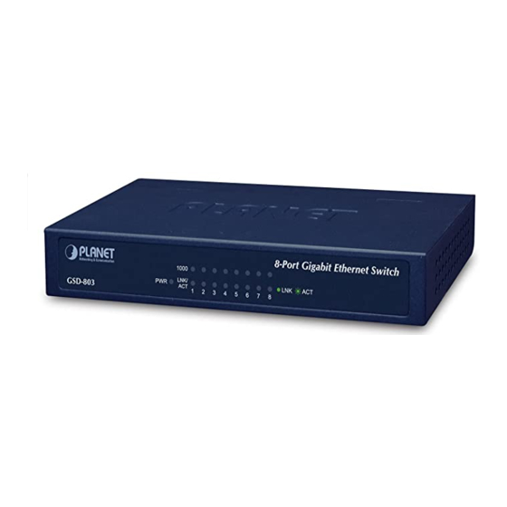
- Page 10 Figure 2-5 & 2-6 show the front panel and rear panel of GSD-803 Figure 2-5 GSD-803 front panel Figure 2-6 GSD-803 rear panel Figure 2-7 & 2-8 show the front panel and rear panel of GSD-804 Figure 2-7 GSD-804 front panel Figure 2-8 GSD-804 rear panel 2.1.3 LED Indicators Color...
-
Page 11: Installing The Switch
receiving data over that port. Lit: indicate that the port is ope rating at 10Mbps. Green Blink: indicate that the switch is actively sending o receiving data over that port. ower Notice: 1. The device is a power-required device, it means, it will not work till it is powered. - Page 12 Note: When choosing a location, please keep in mind the environmental restrictions discussed in Chapter 1, Section 1.4 Product Specification. Step4: Connect your switch to network devices. A. Connect one end of a standard network cable to the 10/100/1000 RJ-45 ports on the Back of the switch. B.
-
Page 13: Switch Operation
3. SWITCH OPERATION 3.1 Address Table The Switch is implemented with an address table. This address table composed of many entries. Each entry is used to store the address information of some node in network, including MAC address, port no, etc. -
Page 14: Store-And-Forward
3.4 Store-and-Forward Store-and-Forward is one type of packet-forwarding techniques. A Store-and-Forward Ethernet Switching stores the incoming frame in an internal buffer, do the complete error checking before transmission. Therefore, no error packets occurrence, it is the best choice when a network needs efficiency and stability. - Page 15 connection is established with another network device (usually at Power On or Reset). This is done by detect the modes and speeds at the second of both device is connected and capable of, both 10Base-T and 100Base-TX devices can connect with the port in either Half- or Full-Duplex mode.
-
Page 16: Troubleshooting
4. TROUBLESHOOTING This chapter contains information to help you solve problems. If Giga Switch is not functioning properly, make sure the Ethernet Switch was set up according to instructions in this manual. Some stations cannot talk to other stations located on the other port Solution: The address table may contain older information than of the... - Page 17 This page intentionally left blank!
-
Page 18: Switch's Rj-45 Pin Assignments
Appendix A A.1 Switch's RJ-45 Pin Assignments 1000Mbps, 1000Base T Contact MDI-X BI_DA+ BI_DB+ BI_DA- BI_DB- BI_DB+ BI_DA+ BI_DC+ BI_DD+ BI_DC- BI_DD- BI_DB- BI_DA- BI_DD+ BI_DC+ BI_DD- BI_DC- Implicit implementation of the crossover function within a twisted-pair cable, or at a wiring panel, while not expressly forbidden, is beyond the scope of this standard. - Page 19 RJ-45 Connector pin assignment Contact MDI-X Media Dependant Media Dependant Interface Interface - Cross Tx + (transmit) RX + (receive) Tx - (transmit) RX - (receive) Rx + (receive) TX + (transmit) 4, 5 Not used RX – (receive) TX – (transmit) 7, 8 Not used The standard cable, RJ-45 pin assignment...
- Page 20 2010-A33110-000...
Need help?
Do you have a question about the GSD-503 and is the answer not in the manual?
Questions and answers