
Related Manuals for GRASS VALLEY T2


Summary of Contents for GRASS VALLEY T2
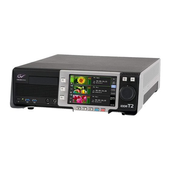
- Page 1 INTELLIGENT DIGITAL DISK RECORDER User Manual — Remote Control — 15 October, 2009...
-
Page 2: About This Manual
If there are any variations between the explanation in this manual and the actual application method, priority is given to the actual application method. • This manual is written for people who have a basic knowledge of how to use a computer. If there are no special instructions, perform the same operation as a normal computer operation. • In this manual, the system of the T2 is called "Workstation". T2 ― User Manual ― Remote Control ―... - Page 3 It is believed that even individuals whom have never experienced such symptoms may be susceptible. If you or close relatives have experienced any of these symptoms, consult a doctor before using this product. User Manual – Remote Control – October 15, 2009 Copyright © 2009 Thomson All rights reserved. T2 ― User Manual ― Remote Control ―...
- Page 4 T2 ― User Manual ― Remote Control ―...
-
Page 5: Remote Control
T2 supports AMP protocol partially (Ethernet only). • According to the GPI input, the corresponding actions are performed. • According to the Playlist > Event settings, the corresponding GPI triggers are output. Functions 1 R1 - VTR mode • As a controller (master), T2 controls the external device (VTR). • When "In-Out Rec" is executed, T2 controls the VTR so as to capture the range between the specified timecodes. 2 P1/P2 – Remote mode As a device (slave), T2 receives the commands sent by external controllers. T2 ― User Manual ― Remote Control ―... - Page 6 COMMAND SPEED DATA TIMER MODE SENSE TIMER MODE DATA The symbols in the table indicate the following: 1) Commands marked with are available for execution when the T2 is performing a relevant operation. If a value is listed in the RETURN column, "RETURN + DATA" is returned. If the column is empty, "10 01 ACK" is returned. 2) Commands marked with return "ACK" or "STATUS" as "RETURN", but do not execute the actual operation. 3) Start Delay value = 0F T2 ― User Manual ― Remote Control ―...
- Page 7 Get Thumbnail A2.0E Set Working Folder A0.0F Get Working Folder A2.14 List First ID A1.15 List Next ID A2.17 ID Duration Request A2.25 ID Start Time Request A0.2A List First Folder A0.2B List Next Folder T2 ― User Manual ― Remote Control ―...
- Page 8 Section 1 ― Remote Control Using AMP commands Before using the AMP commands, make sure that the network settings have been established as below. * The procedures in the Workstation mode are explained here. Click the Config button on the T2, choose General > Network1/2 to open the setting dialog, and set the IP address of the T2. Click the Config button on the T2, choose R1 > Timecode & Remote to open the setting dialog, and set the IP address of the connected device. T2 ― User Manual ― Remote Control ―...
-
Page 9: Gpi Input
• Via the GPI input port (6 pins), T2 can be controlled. Input settings can be specified on the setting dialog, displayed by pressing the Config button and choosing GPI. * The procedures in the Workstation mode are explained here. Available options on GPI Input settings * See the "T2 User Manual – Workstation mode –" for details. • Trigger channel (R1, P1, P2) : M ultiple channels can be simultaneously chosen • Trigger Action • ... -
Page 10: Gpi Output
* I f the operation corresponding to the input trigger cannot be executed, nothing happens. * R egardless of the operation mode or lock status of the GUI, GPI inputs can be received. 4 GPI output • Via the GPI output port (6 pins), triggers are output according to the T2 operation. Output Pin settings can be specified on the setting dialog, displayed by pressing the Config button and choosing GPI, while output Trigger settings can be specified on the setting dialog, displayed by right- clicking on an event list, and choosing Properties > GPI. * The procedures in the Workstation mode are explained here. * G PI output can be output only when issued from content loaded on the P1 channel. T2 ― User Manual ― Remote Control ―... - Page 11 Functions Available options on GPI Output settings * See the "T2 User Manual – Workstation mode –" for details. • Name • Active • High • GPI tab T2 ― User Manual ― Remote Control ―...
-
Page 12: Gpi I/O Connector Pinouts
Input 5 Output 6 Input 6 Common Ground SHELL Common Ground Note T2 iDDR software supports outputs 1-6 and inputs 1-6 only. Pin 7 and Pin 15 are not used. RS422 I/O connector pinouts P1/P2 D-Sub 9pin D-Sub 9pin Signal...
Need help?
Do you have a question about the T2 and is the answer not in the manual?
Questions and answers