GRASS VALLEY KAYENNE User Manual
Video production center
Hide thumbs
Also See for KAYENNE:
- User manual (424 pages) ,
- Installation & service manual (389 pages) ,
- Datasheet (8 pages)

Subscribe to Our Youtube Channel
Related Manuals for GRASS VALLEY KAYENNE


Summary of Contents for GRASS VALLEY KAYENNE
- Page 1 KAYENNE/KARRERA/ GV KORONA GV K-FRAME XP Video Production Center User Manual VERSION 16.0 076159301-AC 2021-10-15...
-
Page 2: Patent Information
Valley USA, LLC, or one of its affiliates or subsidiaries. All other intellectual property rights are owned by GVBB Holdings SARL, Grass Valley USA, LLC, or one of its affiliates or subsidiaries. All third party intellectual property rights (including logos or icons) remain the property of their respective owners. -
Page 3: Table Of Contents
Flat or Curved Control Panel Orientation................24 Control Panel Stripes ........................24 Touch Screen Menu Panel ......................24 Basic Single Suite Kayenne Panel System ................24 Multiple Suite Kayenne Panel System Example ..............24 Karrera Control Surface ....................... 26 Basic Single Suite Karrera Panel System ................27 GV Korona Control Surfaces ...................... - Page 4 Notices 4 Suite Preferences ..............41 Suite Preference Settings ........................41 About Suite Resources ........................41 Aux Bus Transitions ........................41 About Suite Signal Type—HDR Mode ................... 41 About Re-Entry ............................43 About Source Patching ........................43 Engineering Names, Eng IDs, and Logical IDs ..............45 Alternative Source Names ......................
- Page 5 Enable DPMs from the Menu ....................93 iDPMs ..............................94 2D DPMs ............................95 Kayenne (only) Parameter and Soft Knob Controls ..............95 DPM Source and Target Space Explained ..................96 Tally and DPMs ..........................96 DPM Transform Menu ......................... 96 Enable DPM Transforms in the Menu ..................
- Page 6 Notices Defocus Pane ..........................107 NAM Matte Pane ......................... 108 DPM Lighting Menu ........................... 108 Shadow Control Pane ........................ 108 Light Type Pane ........................... 108 Light Type ............................109 Light Control Pane ........................109 Lighting Path Controls ......................110 Lighting with Page Turn/Roll Effects ................... 110 Lighting and Post Transform Space ..................
- Page 7 Macro Attachments ........................139 “Disabled” is the Default for the Macro Attachable Control Panel Preference ..140 Macro Attachments and Importing Show Files ............... 140 Kayenne Macro Operations ..................... 140 Record a Macro ..........................141 Insert a Macro Delay ........................141 Insert a Macro User Pause ......................
- Page 8 Delegate a Switcher Mode to a Source Select Button Row ......... 163 Source Select Button Row to Aux Mode Delegation ............. 163 Panel Memory and P-MEM Registers ................... 164 Learn a Kayenne P-MEM Register ..................164 Recall a Kayenne P-MEM Register ..................165 Learn a Karrera/GV Korona P-MEM Register ..............165 Recall a Karrera/GV Korona P-MEM Register ..............
- Page 9 7 Switching Basics ..............178 Basic Switcher Control Surfaces ..................... 178 Kayenne Control Panel Overview ....................178 Setting Panel Saver Mode ......................179 Module Overview ........................180 Transition Module ........................180 Local E-MEM Module ......................... 184 Master E-MEM Module ......................185 Multi-Function Module ......................
- Page 10 Take XPression IDs from an External Device ..............236 Using Extended GFX XPression Controls ................237 Fire XPression GPI Sets ......................238 Kayenne Device Control from the Control Panel ..............238 System Bar ............................. 239 Local Aux Module ........................239 About Multi-Function Module Device Control ..............
- Page 11 About E-MEM Control of R-MEM ................... 260 R-MEM Disk Storage ........................260 R-MEM Enable Control and Auto Recall ................260 E-MEM Prefs Assignment ......................260 Learn R-MEMs from the Control Panel ................261 Change R-MEM on an Existing E-MEM Register ............... 262 Loading R-MEM Registers ......................
- Page 12 Notices Build Background E-MEM Transitions ................. 282 Building Keyer E-MEM Transitions ..................283 Changing the Length of an E-MEM Transition ..............284 Preventing Elements from Transitioning in E-MEMs ............. 285 Return to Normal Technique ....................285 About Source Holds in Effects ......................285 Set a Source Hold in a New Effect ..................
- Page 13 Adjust a 2D DPM Image with Edge Pinning Pan and Scan .......... 334 Set Edge Pinning with the Kayenne Multi-Function Module ........335 Pan and Scan a 2D DPM Image with the Kayenne Multi-Function Module ..336 About Copy/Swap ..........................337 Copy Swap Menus ........................
- Page 14 Still Playback from the Menu ....................354 Modify a Still ..........................355 Set Freeze Mode .......................... 355 Kayenne Image Store Device Control .................. 355 Kayenne System Bar Control....................356 Image Store Movies Option ....................357 GV K-Frame XP Image Store Movie Lengths ..............357 Image Store Movie Storage Capacity ..................
- Page 15 Schedule a Backup ........................378 Restore Cache from the Local Drive ..................378 About Image ReStore ........................ 379 Image ReStore Button Functions ..................379 Enable Image ReStore ....................... 379 Editing Files in Image ReStore ....................380 Configure a Networked PC for Image Store File Sharing Windows ......380 Create an Images Directory and Configure it for Sharing ..........
- Page 16 Table of Contents...
-
Page 17: Documentation & Media
Tally state of the switcher. The Ethernet Tally Software Development Kit (SDK) is available to approved vendors who need to interface with the Ethernet Tally system. Contact Grass Valley Product Management for more information on this SDK. -
Page 18: Video Tutorials & Training
Documentation & Media Video Tutorials & Training Video Tutorials & Training Grass Valley Video Production Center switcher video tutorials and training can be found in Support | Documentation Libraries at www.grassvalley.com and on YouTube. -
Page 19: Introduction
Introduction Overview The Grass Valley K-Frame family of multi-format digital production switchers provides powerful, ground-breaking features designed to meet the widest range of requirements for live studio, mobile, and post-production applications. The following Video Processors are the heart of the system, providing extensive video switching and signal processing capabilities: •... - Page 20 M/E outputs. • Aux bus transitions for dissolves and wipes on aux bus outputs. • Interfaces with Grass Valley routers supporting Native Protocol. • Optional Integrated Image Store capable of delivering up to 32 GB, 64GB or 128GB storage of Stills (3,000/6,000/12,000 images) or “Movies”...
- Page 21 Kayenne/Karrera/GV Korona User Manual • Up to 16 iDPMs (Integrated Digital Picture Manipulators), assigned as either floating iDPMs on any keyer or within an eDPM at user’s discretion. K-Frame XP Compact Frame • Up to 80 inputs and 48 outputs.
-
Page 22: K-Frame Control Surfaces
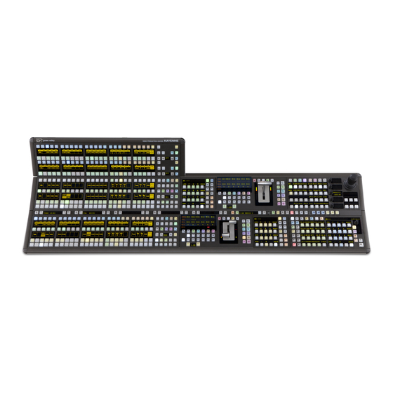
K-Frame Control Surfaces Kayenne Control Surface A Kayenne control surface typically consists of a Control Panel, a Menu Panel with an included articulated support arm, a Panel Control Unit (PCU) frame, and optional Satellite Panels. • This control surface has an innovative modular design. Representative Kayenne control surfaces are shown in the following illustrations. -
Page 23: Flat Or Curved Control Panel Orientation
Flat Control Panel Assembly Control Panel Stripes The main Kayenne Control Panel is organized into from one to five Stripes. Each Stripe consists of a tray and its complement of drop-in modules. An M/E Stripe has a module for Source Selection, Transition, and individual E-MEM control. Additional Master E-MEM, Machine Control, Multi-Function, and Local Aux modules are populated to complete the control surface functionality. -
Page 24: Basic Single Suite Kayenne Panel System
Menu Panel, and a Video Processor Frame. The Control Panel and Menu application make up a control surface associated with that frame. The Kayenne Control Panel and Menu Panel have associated active electronics housed in the Panel Control Unit (PCU). - Page 25 Kayenne/Karrera/GV Korona User Manual Hardware resources in the Video Processor Frame can be assigned to an individual suite during configuration, essentially creating up to four separate switchers sharing one frame. Suite 1 KSP 1-ME (Customer Supplied PC) Suite 2 K-Frame...
-
Page 26: Karrera Control Surface
Introduction Multiple Suite Kayenne Panel System Example Karrera Control Surface A Karrera control surface typically consists of a Control Panel and a Menu application. Representative Karrera control surfaces are shown in the following illustrations. Bus/Row Delegation Local E-MEM Modifier Section &... -
Page 27: Basic Single Suite Karrera Panel System
Kayenne/Karrera/GV Korona User Manual The Menu Panel has a standard VESA-75 hole pattern and M4 threads, compatible with this and many other mounting devices. The Menu Panel also has four USB ports, two on the right side edge of the panel and two on the back for keyboard and mouse (wired or wireless are supported). -
Page 28: Gv Korona Control Surfaces
K-Frame V-series 3-RU Multiple Suites and Control Surfaces Example Any K-Frame Kayenne, Karrera, or GV Korona Control Panel can be configured with any K-Frame Video Processor. The K-Frame system can be subdivided into four suites and each suite can have up to two control surfaces. Hardware resources in the Video Processor Frame can be assigned to an individual suite during configuration, essentially creating four separate switchers sharing the one Frame. -
Page 29: Supported Control Protocols
• AMP (advanced media protocol) for Profile PVS, Profile XP Media Platform, K2, M-Series, Turbo iDDR, and T2 iDDR systems over Ethernet • Grass Valley Native Protocol for routers/routing control systems (Trinix/Trinix NXT, Venus™, Triton™, and third-party routers; Jupiter NV9000 and NV920, and Encore router control systems) •... - Page 30 • K-Frame Ethernet Tally protocol • Ethernet CPL to control Grass Valley external remote AUX Panels • Grass Valley Editor protocol • SNMP system monitoring • Serial and Ethernet VDCP • Control of Ross Xpression using RossTalk • Control of RossTalk GPI devices.
-
Page 31: Panel Preferences
Default mapping includes one-to-one logical input mappings, for example inputs labeled 1-28 to Source Select buttons 1-28 (on a 35 button panel) or Aux 1- Aux 96 with a Local Aux panel (Kayenne/Karrera). There are four default M/E outputs delegated for reentry (as inputs) per shifted row (1st row M1 A - M4 A, 2nd row M1 C - M4 C, etc.), 2nd and 3rd Shift Levels, and Delegation buttons. - Page 32 Control Panel. For example if the menu has not been associated with a Control Panel or if using a 15 or 25 button Control Panel with a 35 button Aux Panel (Kayenne/Karrera), the button count can be selected manually (this selection is automatic if a panel has been associated in the Associated Panel data pad, in the Eng Setup, Node Settings, Frame Suite Nodes &...
-
Page 33: Map Control Panel Source Select Buttons
Kayenne/Karrera/GV Korona User Manual The Logical/Fixed Sources area: • Sources scrolling list—used to locate assignable sources. You can choose from Logical or Fixed Sources • Source Number data pad—displays a data entry pop-up when selected and is used to assign a Logical source number to a source select button •... -
Page 34: Assign Control Panel Source Colors
Panel Preferences Assign Control Panel Source Colors Set all system colors: 1 Select User Setups, Panel Prefs, Panel Color Scheme. 2 From the Color Scheme button list, left, select the Rainbow, Tinted, or Opal buttons. 3 Save the Panel Color Scheme settings in the File Ops, User Setups menu. Set delegation button colors: 1 Select delegation buttons in the center pane. - Page 35 Kayenne/Karrera/GV Korona User Manual 1 Select User Setups, Panel Prefs, Source Colors. 2 Select the Logical ID of the desired source. 3 Select the desired color in the System Colors or User Colors pane (see Define User Colors). Note: Use the Default Bus Color button in the System Colors pane to return to the Panel Color Scheme default.
-
Page 36: Map Remote Aux Panel Sources To The Control Panel
Map Remote Aux Panel Sources to the Control Panel The Remote Aux Panel Server Ethernet IP is set to the Video Processor Frame of the GV Switcher system, see the Kayenne/Karrera/GV Korona Installation & Service Manual for more information. 1 Select Eng Setup, Node Settings, Remote Aux Button Map. -
Page 37: Map Remote Aux Panel Delegation Buttons (Logical Mapping)
Kayenne/Karrera/GV Korona User Manual Map Remote Aux Panel Delegation Buttons (Logical Mapping) You can map Remote Aux buses to Panel Delegation buttons to make them available as sources to the Control Panel. When multiple Remote Aux Panels are selected, changing one button’s mapping changes the button mapping for all selected Remote Aux Panels. -
Page 39: Suite Preferences
Suite Preferences Suite Preference Settings Suite Preferences define the Video Frame settings for the switcher system. You can customize the Suite Preferences for each suite. Some Suite Preference settings are described in the Advanced section (Advanced Operations, on page 271), along with operations, including E-MEM, Re-Entry, GPI Inputs, Image Store, and Transition Chaining. - Page 40 Suite Preferences About Suite Signal Type—HDR Mode HDR Payload ID Specifications Suite Signal Type Specifications Transmission Recommendation Description HDR: Rec BT2100 ITU-R BT.2100-2 (07/2018) Image parameter values for high dynamic range television for use in production and international (HLG, PQ) program exchange Colorimetry: Rec BT2020 ITU-R BT.2020-2 (10/2015) Parameter values for ultra-high definition television systems for production and...
-
Page 41: About Re-Entry
ME. (Secondary into the Primary or Primary into the Secondary). A Grass Valley switcher system supports M/E re-entry in any order. For example, an output of ME-2 can be sent to ME-1, and an output of ME-1 can be sent to ME-3. Infinite looping re-... - Page 42 Suite Preferences About Source Patching By default, engineering source IDs are mapped one-to-one with logical IDs but Source Patching can be used to quickly set up production elements for use in a different facility. For example, a show’s effects, DDR clips, and other recorded material may have been built in one production truck with one set of devices, but the next show is scheduled for a different truck.
-
Page 43: Engineering Names, Eng Ids, And Logical Ids
Eng ID number will appear on all the GV Switcher system displays. If an engineering name has been entered (see the Kayenne/Karrera/GV Korona Installation & Service Manual) then the engineering name will be displayed on all the system displays, including menus. -
Page 44: Source Patching And Effects Portability
Suite Preferences Source Patching and Effects Portability example, if an alternative name is entered in the OLED Name column for a source and the other two columns remain blank, the Menu Name takes the OLED Name (OLED Name being first to the left of the Menu Name) but the Panel Name takes the Eng. Source column’s name (first name to its left). -
Page 45: Patch Engineering And Fixed Sources To Logical Ids
Kayenne/Karrera/GV Korona User Manual Once the Suite Prefs and effects are loaded at the new facility, go to the Source Patch menu and map the appropriate Engineering sources of the new facility to the original list of Logical sources. Your effects should now run as previously designed without having to edit or rebuild them. -
Page 46: Patch A Key Input From Another Source
Suite Preferences Patch a Key Input from Another Source • Menu Name (Menu Name column)—Source will appear with this name in the menus only. To change the source patching, select an Engineering/Fixed source to be associated with the currently selected Logical source with the Engineering Source data pad or by scrolling the Engineering Source IDs Button pane. -
Page 47: About Default Keyframe
Kayenne/Karrera/GV Korona User Manual About Default Keyframe Default Keyframe settings are applied when an empty register is recalled and when the CWB (Clear Working Buffer) button is pressed in the Master E-MEM ( EMEM Edit , CWB button) of the Control Panel. -
Page 48: About The Preview Prefs Menu
Suite Preferences About the Preview Prefs Menu 4 Save your learned Default Keyframe settings in the File Ops, E-MEM menu. • Pressing the Factory Default button overwrites the Default Keyframe with factory defaults. About the Preview Prefs Menu Preview displays on the Preview Prefs menu can be adjusted by the user, including Safe Area borders, Crosshairs, and the selection of optional multi-image M/E Viewer layouts. -
Page 49: About The Multiviewer Prefs Menu
Kayenne/Karrera/GV Korona User Manual About the Multiviewer Prefs Menu The K-Frame Multiviewer Prefs menu provides five layout configurations (six on the K- Frame XP), tally preference settings, assignable Fixed and Logical inputs, Switched Preview or Aux Buses to each video window. Multiviewer menu preferences are saved as part of Suite Prefs and can be loaded or excluded as part of the Load Granularity in the File Ops, Eng Setup menu. -
Page 50: Set Multiviewer Layout Preferences
Suite Preferences Set Multiviewer Layout Preferences Set Multiviewer Layout Preferences Choose from one of five Multiviewer layouts: 1 Select User Setups, Suite Prefs, Multiviewer Prefs. 2 If there is more than one Multiviewer acquired, press the Identify button to display the available Multiviewers in the top, middle of the monitor so the correct Multiviewer will be selected for adjustment. -
Page 51: About Mv Green Relay Tally Calculations For Multiviewer On-Air And Green
Kayenne/Karrera/GV Korona User Manual c Locate the noted source by either scrolling through the Source list (Logical ID column) or clicking on the Engineering Source ID data pad and entering the Source Number noted from the Multiviewer Prefs menu. d Select the Menu column data pad for the source and enter the new name in the pop-up keyboard, and select Enter. -
Page 52: About File Operations
Suite Preferences About File Operations 6 Turn on the calculation by selecting the Cal cO n button (highlights green when on). 7 Select the M V Taly tab. 8 Select the LAP configured tally calculation; for example Cal c1 LAP 1 . About File Operations The Switcher menu file browser allows you browse through folders on the local Menu Panel hard disk, the GV Switcher Video Processor Frame, and the entire network file hierarchy of... -
Page 53: About The File Ops Menus
Kayenne/Karrera/GV Korona User Manual Experienced users may want to create their own sets of preference files and save only critical ones in the Frame User directory. Other files can be loaded using the browser from any directory or be placed on a personal USB Memory Stick. -
Page 54: Gv Switcher File Type Extensions
Suite Preferences GV Switcher File Type Extensions functions apply to the left-hand pane only, and are inactive during a Copy/Paste operation. 4 Navigate the right-hand pane to the desired directory, using its navigation buttons. 5 Select the Paste button. A message indicating the file is being copied will be displayed, and when finished the right-hand pane will close. -
Page 55: About Show Files
Kayenne/Karrera/GV Korona User Manual GV Switcher System File Extensions Icon Example File Type Extension Panel Prefs .GVC .GVF .GVJ Suite Prefs .GVS .GVZ Eng Setup .GVE .GVH. .GVN E-MEM Register .GVR R-MEM Register .GVY Panel Memory .PMEM Register Cues Register .GVB... - Page 56 Suite Preferences About Show Files be affected, other aspects of system operation (source mapping, source name displays, available effects, etc.) will change depending on what files are being loaded. Note: Verify that the Show includes/excludes the desired preferences and settings before loading, especially if the system is currently on-air. •...
- Page 57 Kayenne/Karrera/GV Korona User Manual Create a Show File 1 Select File Ops , Show Files . CAUTION: : The Eng Setup button (lower right of menu) is off by default because ports and server IPs are unique. Transferring Show files from one location to another (including suites) requires careful planning to prevent interruption.
- Page 58 Suite Preferences About Show Files Note: A best practice is to set register ranges all each time there is an update (e.g. E-MEM 0-999, Macro 1-999, etc.), this will ensure that new registers are included. 5 Select the Create button in the Create Show pane. Result: The Show file is created with the selected file types and appears in the directory.
- Page 59 Kayenne/Karrera/GV Korona User Manual The selected show file is automatically displayed in the left-hand directory pane. 3 Select the Load Show button. Note: A pink highlighted load list item means a full show, otherwise it is a partial show.
- Page 60 Suite Preferences About Show Files Update a Show File 1 Select File Ops , Show Files . CAUTION: : The Eng Setup button (lower right of menu) is off by default because ports and server IPs are unique. Transferring Show files from one location to another (including suites) requires careful planning to prevent interruption.
-
Page 61: About The File Ops, All Files Menu
Kayenne/Karrera/GV Korona User Manual About the File Ops, All Files Menu The File Ops, All Files menu is used to quickly sort and locate files by using the Sort By Type , Sort By Name , and Reverse Order (reorders the current sort to ascending or descending) buttons and manage all files types in the System and Remote Storage menu tab directories. -
Page 62: Save User Setups
Suite Preferences Save User Setups Save User Setups Selecting a User Setup file in the System or Remote Storage menu tab and selecting Save overwrites the file. 1 Select File Ops , User Setups . 2 Select Panel Prefs or Suite Prefs button. 3 In the System or Remote Storage menu tab (left side of menu), navigate to the folder you want the User Setup to be saved. -
Page 63: Load User Setups
Kayenne/Karrera/GV Korona User Manual Load User Setups 1 Select File Ops , User Setups . 2 Select Panel Prefs or Suite Prefs button. 3 In the System or Remote Storage menu tab (left side of menu), select a Panel Prefs or Suite Prefs file. -
Page 64: Save Source Tables Or Source Rules
Suite Preferences Save Source Tables or Source Rules Save Source Tables or Source Rules Save operations for the Source Tables and Source Rules menus are identical. Saving Source Tables will be described in this example. Note: Selecting a Source Rules or Source Tables file in the System or Remote Storage menu tab and selecting Save overwrites the file. -
Page 65: Load Source Tables Or Source Rules
Kayenne/Karrera/GV Korona User Manual Load Source Tables or Source Rules Load operations for the Source Tables and Source Rules menus are identical. Loading Source Tables will be described in this example. 1 Select, File Ops , Source Tables . 2 In the System or Remote Storage menu tab (left side of menu), navigate to the Source Tables file you want to load. - Page 66 Suite Preferences About Register-Based File Ops Menus saved locally to the Frame C: drive cannot be renamed. If you try to rename an E-MEM file on the Frame C: drive an error message will appear in the message area. If for some reason an E-MEM file needs to be renamed, copy it to a local drive and rename it.
- Page 67 Kayenne/Karrera/GV Korona User Manual 1 Select, File Ops , E-MEM . 2 In the System or Remote Storage menu tab (left side of menu), navigate to the folder you want the registers to be saved. 3 Select All or enter specific registers or a range of registers and/or a start register.
- Page 68 Suite Preferences About Register-Based File Ops Menus Load E-MEM Registers Load operations for the Panel MEM, E-MEM, Macros, Cues, and Router MEM menus are identical. Loading E-MEM registers will be described in this example. 1 Select, File Ops , E-MEM . 2 In the System or Remote Storage menu tab (left side of menu), navigate to the folder containing the registers to be loaded.
-
Page 69: Save Eng Setups
Kayenne/Karrera/GV Korona User Manual Save Eng Setups Note: Selecting an Eng Setup file in the System or Remote Storage menu tab and selecting Save overwrites the file. 1 Select File Ops , Eng Setups . 2 In the System or Remote Storage menu tab (left side of menu), navigate to the folder you want the Engineering Setup to be saved. - Page 70 Suite Preferences Load User Setups 2 Select Panel Prefs or Suite Prefs button. 3 In the System or Remote Storage menu tab (left side of menu), select a Panel Prefs or Suite Prefs file. 4 Optionally, select either the Panel Prefs or Suite Prefs button in the center menu pane and in the Load Granularity pane, enable or disable preferences and settings that will be loaded as part of the user setups.
-
Page 71: Video Mix/Effects
Video Mix/Effects M/Es and Keyers A GV K-Frame XP M/E is a subsystem of a video production switcher that can create a composite of two or more pictures. An M/E includes multiple source selection buses and provides transition (mix and wipe) and keying capabilities on the selected signals. Six Keyer System Example Keyers are used to insert part of one picture into another to create a composite picture. -
Page 72: Chroma Key
Video Mix/Effects Chroma Key The GV Switcher system also supports self keys and split keys. Chroma Key The GV Switcher system features the chroma keyers option with powerful controls. These controls offer subtle adjustments to allow successful keying of difficult subject matter (fine hair, smoke, translucent objects, etc.), and to overcome some problems resulting from imperfect chroma key set coloring or lighting. -
Page 73: Primary Suppression
Kayenne/Karrera/GV Korona User Manual individual scene. You may need to go back to earlier steps and readjust previous settings to optimize the key. Understanding what the chroma key controls do will help you decide what adjustments are required for your individual situation. -
Page 74: Extra Chroma Key Controls
Video Mix/Effects Extra Chroma Key Controls chroma suppression is the correct setting for all chroma keys. At this point, you will probably see a line through the center of the vector scope. With increased selectivity, this line will become an arc. •... -
Page 75: Configure Auto Setup
Kayenne/Karrera/GV Korona User Manual Fringe is used to restore color to the gray portions of the foreground color resulting from secondary suppression adjustments. This control is only active when secondary suppression is on. Shdw provides controls of shadows that fall on the backing. Shadow Clip and Shadow Gain allow selecting the range of the luminance portion of the foreground that produces a shadow. -
Page 76: Reshape A Chroma Key Using Auto Setup
Video Mix/Effects Reshape a Chroma Key Using Auto Setup 8 Press the button on top of the joystick. The chroma key will be set up automatically using the average of the colors selected by the cursor box. Because Reshape was off, fine edges of the key will be preserved. -
Page 77: Apply Chroma Key Secondary Color Suppression
Kayenne/Karrera/GV Korona User Manual 2 Select Show Key in the Keyer menu and look at the M/E preview output on a picture and waveform monitor. 3 Adjust Clip Hi so that all areas of the foreground objects are white. If Clip Hi is set too... - Page 78 Video Mix/Effects Apply Chroma Key Secondary Color Suppression Note: If Reshape has been applied, it is unlikely enough edge detail will remain to use secondary color suppression. 1 Select the stage 3 Sec Suppress data pad and then select the Secondary Suppress button to activate this feature.
-
Page 79: Generate Background Mattes
Kayenne/Karrera/GV Korona User Manual Generate Background Mattes Background matte generators create colors and washes. These can be used, for example, as the backgrounds for keys. Background mattes cannot use the wipe pattern generators available to keyer and wipe mattes, and cannot use Utility video as a wipe source. Instead background mattes employ a simple dedicated wipe generator that creates a single, straight line. -
Page 80: Split A Key
• Configure a source in the Eng Setup/Source Destination menu that uses different video for cut than for fill. That split key will initially be used whenever that engineering source is selected. See the Kayenne/Karrera/GV Korona Installation and Service Manual for more information. -
Page 81: Set Keyer Priority
Kayenne/Karrera/GV Korona User Manual The ME Status display in the Transition area shows the source names of any key cut signals. Note: Split Key will be shown in the Modifier area Control Panel Display. Set Keyer Priority The GV Switcher system has four or six keyers per M/E so complex stacking is possible. Keys can be placed between other keys, using key priority. -
Page 82: About Key Store
Video Mix/Effects About Key Store 1 Press the Key Prior Transition Element button on the Control Panel. 2 If not already set up, turn on the desired keys and arrange them so they overlap, observing the Program monitor. This will make the changes in key priority visible. For demonstration purposes, you can use four preset pattern keys. - Page 83 Kayenne/Karrera/GV Korona User Manual Each Key Store can save the use of other switcher resources. For example instead of using an Image Store channel or another keyer, you could store a station ID or a replay graphic (still) for a sports show in a Key Store and switch the image within the keyer.
-
Page 84: Set A Pattern Mix
Video Mix/Effects Set a Pattern Mix You can ‘Grab’ both a video and key frame simultaneously by selecting either the Grab V&K 1 or Grab V&K 2 button, located below each Frame Store page, or you can select a Grab button for any of the four Video/Cutout Frame Stores. Once you grab fill and key images in Key Store, they are available for the selected key source. -
Page 85: Source Memory
Kayenne/Karrera/GV Korona User Manual 2 Select the P1 pattern to be used by selecting the Wipe Pattern button between the Pattern Mix and Generator/Border data pads, and then selecting one of the displayed patterns in the Pattern tab on the right. - Page 86 Video Mix/Effects Source Memory Source Memory settings for a keyer source are only applied when that source is selected on that keyer bus. Selecting on that keyer bus a different source that does not have learned Source Memory will restore the previous keyer settings. Source Memory keying settings include: •...
- Page 87 Kayenne/Karrera/GV Korona User Manual 4 Select the Learn button. The settings are saved for that keyer source on that M/E’s keyer bus, and will be applied whenever that source is selected on that M/E’s keyer bus. When a keyer source with settings saved to Source Memory is selected on a keyer bus, the Source Memory button is highlighted when that keyer is selected in the Keyer Mode menu.
-
Page 88: About Acquiring Dpms
Logical Resources of the Eng Setup, Acquire Resources menu, in the DPM Chns data pad. eDPM resources must be allocated. Note: 2D DPMs are available on all M/Es including the eDPM. To move resources between suites, refer to the Kayenne/Karrera/GV Korona Installation & Service Manual. -
Page 89: Acquire An M/E Resource For Edpm
Kayenne/Karrera/GV Korona User Manual Acquire an M/E Resource for eDPM A full M/E is used as an eDPM logical resource so that M/E will be unavailable until released. 1 Select Eng Setup , Acquire Resource . 2 Select the eDPM button in the Logical Resources pane. -
Page 90: Enable/Delegate Dpm Channels
(for DPM suite acquisition, see Kayenne/Karrera/GV Korona Installation & Service Manual). Enable DPMs on the Kayenne Control Panel 1 From the Kayenne Control Panel, in the MFM (Multi-Function Module) Home menu, press an ME button. 2 Press a Key button 1-6 or hold and press for multiple channel control. -
Page 91: Enable Idpms On A Karrera Control Panel
2 Press a channel button or hold and press for multiple channel control. Enable a 2D DPM on a Keyer 1 From the Kayenne Control Panel, in the MFM (Multi-Function Module) Home menu, press an ME button. 2 Press a Key button 1-6 or hold and press for multiple channel control. -
Page 92: Idpms
Share iDPMs/eDPMs from a pool of up to 16 physical DPMs (four DPMs per dual M/E board). DPMs are licensed in pairs. Kayenne provides two DPM options: • iDPM—Full DPM including transform engine for complex effect manipulation, up to 16 iDPMs can be licensed in pairs, •... -
Page 93: 2D Dpms
There are six 2D DPMs per M/E, including the eDPM. Each can be sized, scaled, and moved along X and Y axis. 2D DPMs match the iDPM positioning of Post Transform control. Kayenne (only) Parameter and Soft Knob Controls When any of the MFM positioning parameter buttons are pressed, the soft knobs and joystick buttons are delegated for control of that parameter. -
Page 94: Dpm Source And Target Space Explained
Video Mix/Effects DPM Source and Target Space Explained For the CROP, SHAD, FILM, and FRZ buttons, DELG must be pressed below each to delegate the MFM to those functions (not available for 2D DPMs). DPM Source and Target Space Explained Source space refers to a key moving along the X, Y, and Z axes of the i m a ge pl a n e of th e channel while Target space refers to the key moving along the X, Y, and Z axes of the monitor (refer to the Switcher Concepts Manual on grassvalley.com for a complete... - Page 95 Kayenne/Karrera/GV Korona User Manual Some functions (Crop, Reverse, Skew, Aspect, and Post Transform) are inactive for these Global Channels so they are grayed out. Global Channel assignment information will appear in the ME/Keyer data pad (PRI Glb /SEC Glb). Any transform type is applied across all keyers when they are assigned as global, i.e. Locate, Rotate, Spin, and Perspective.
-
Page 96: Key Off Control
Video Mix/Effects Key Off Control for that M/E, select those keyers, and apply a Spin transform. All three keyers would spin around the global axis. Independant Axis Rotation Global Channel Axis Rotation Spin Transform Key Off Control The Key Off button in the iDPM, Transform menu is used to turn off the key signal processing for the delegated keyer, resulting in a full raster image. -
Page 97: Easy Cube Control
Kayenne/Karrera/GV Korona User Manual you want to fly a graphic that is normally accompanied by a key signal. Turning the key off forces the graphic to full raster, ignoring the key. The Key Off button is inactive for Global channels. -
Page 98: Clear Transforms
Video Mix/Effects Clear Transforms turn off transform interpolation and hold each keyframe’s values with the Path Hold select button. Note: Use the Path controls in the E-MEM & Timeline menu to affect all DPM transform and effect modifiers. Path controls in the DPM menus are only used to adjust path parameters of individual values of a transform or effect modifiers. -
Page 99: Shadow Controls
Kayenne/Karrera/GV Korona User Manual Note: The Borderline menu is also available in the Keyer, Borderline menu which you would use if you did not have iDPM licenses. Shadow Controls The Shadow feature is turned on with the Shadow On button in the lower left pane. When turned on, soft knob controls become available on the right. -
Page 100: Glow Color
Video Mix/Effects Glow Color Glow adds a soft edged variable opacity border around keys, leaving the original keyed image unmodified, and is a standard feature available on all GV Switcher systems. Off—The Glow effect is deactivated. Glow—The Glow effect is applied around the keyed image which remains visible. Full raster video must be resized or cropped for glow to be visible. -
Page 101: Idpm/2D Dpm Film Look Menus
Kayenne/Karrera/GV Korona User Manual iDPM/2D DPM Film Look Menus With Film Look, you can create a flicker or strobe effect (similar to an old film run through a movie projector). The affect can be adjusted to the desired look by setting the interpolation (Frame, Field, or Adaptive for Video and Key), turning on Input Freeze and/or Strobe and adjusting those parameters with the soft knobs. -
Page 102: Mod Type Pane
Video Mix/Effects Mod Type Pane • H/V Angle—defines the angle of the Position Modulation with respect to the source X and Y axes. Mod Type Pane With an axis selected, you select the type of modulation to be applied to that axis (Position Mod or Size Mod), or no modulation at all with the Mod Off button in the Modulation Mode pane. -
Page 103: Page Turn Pane
Kayenne/Karrera/GV Korona User Manual Select the Page Turn/Roll Kurl Mode button to access the Page Turn and Roll controls. Page Turn Pane The page mode (Page Turn or Page Roll), and orientation of the fold (Fold Over or Fold Under the original plane) are selected in the Page Turn pane, bottom right of menu. -
Page 104: Slits Mode
Video Mix/Effects Slits Mode • Aspect—stretches the ripple horizontally or vertically. • H/V Angle—adjusts the angle of the ripple, horizontally and vertically. Slits Mode Slits is an effect in which the source video is split into a number of parallel slits. The width of the slits may be uniform or random, and an angle may be specified. -
Page 105: Dpm Splits Mirrors Menu
Kayenne/Karrera/GV Korona User Manual DPM Splits Mirrors Menu Located in the DPM, Splits & Mirrors menu, the Splits and Mirrors effect allows you to divide a picture horizontally and/or vertically, and create mirror images of the image along these axes. -
Page 106: Nam Matte Pane
Video Mix/Effects NAM Matte Pane • Defocus—The Defocus effect is applied to the original keyed image. • Defocus NAM + —The defocused image is compared to the original image on a pixel by pixel basis, and the lighter (higher luminance) pixel of the two is used in the final image. Defocus NAM + can be used to simulate a fog filter type effect. -
Page 107: Light Type
Kayenne/Karrera/GV Korona User Manual source. The Light Type pane is used to turn on or off the delegated light source and provides various other controls of that light source. Soft knobs are activated when appropriate to control the various lighting parameters. -
Page 108: Lighting Path Controls
Video Mix/Effects Lighting Path Controls Lighting Path Controls Path controls are available for Lighting parameters and provide soft knob control for Light Tension, Continuity, and Bias when the Curve button and Curved data pad are selected. A Path Hold button is also provided. Lighting with Page Turn/Roll Effects To use Lighting with Page Turn/Roll, you need to use one keyer for the Front side of the Page Turn and another keyer for the Back side. -
Page 109: Motion Decay Mode
Kayenne/Karrera/GV Korona User Manual Motion Decay Mode Causes motion in the image to leave a blurred remnant in the area from which it was removed. Appearance button—displays the “Pic” or Picture Decay value from the soft knob data pad. Wind button—displays the Direction and Velocity (speed) values from the soft knob data pads. -
Page 110: Montage Mode
Video Mix/Effects Montage Mode • Keyframe Reset button—is used to control a frozen image. It is only available when the Keyframe mode button is selected as the Strobe Type. • ON—A keyframe triggers a reset, followed by a new single strobe. It resets that loop by creating a new frozen image at each keyframe that has the Keyframe Reset button on. -
Page 111: Trails Mode
Kayenne/Karrera/GV Korona User Manual • ON—accumulates a field/frame of video within the Output Recursive loop. • OFF—No action is taken. Mode buttons: • Over—places the image over the remnant or “montage”. • Under—places the image under the remnant. • Erase—erases the image and remnant. -
Page 112: Dpm Global Channel Control Over Multiple M/Es
Video Mix/Effects DPM Global Channel Control Over Multiple M/Es Keyframe button—freezes a new image at each keyframe. Loop button: • ON—starts the recursive effect. • OFF—stops the recursive effect and returns to live video. Keyframe Reset button — is used to control when images are frozen. It is only available when the Keyframe mode button is selected as the Strobe Type. -
Page 113: Set Up A Dpm Secondary Global Channel
Kayenne/Karrera/GV Korona User Manual Set Up a DPM Secondary Global Channel By splitting the M/E into Primary and Secondary partitions, you can assign keyers in the Secondary Partition to global control just as with the Primary Partition. This allows you to create very complex effects on both outputs, including making keys on the Primary Partition visible on the Secondary Partition and vice versa. -
Page 114: Adjust Idpm/2D Dpm Border Edges
Video Mix/Effects Adjust iDPM/2D DPM Border Edges Note: Color is applied to the entire border, there is no independent control. Adjust iDPM/2D DPM Border Edges The width and softness of DPM Borders can be adjusted for each edge independently, using the soft knobs or pop-up keypads. 1 Select DPM , Borders . -
Page 115: Edpm Partitioning
Kayenne/Karrera/GV Korona User Manual an external DPM. Also, you can have multiple E-MEM registers recalling the same eDPM effect. The switcher timeline and the eDPM timeline can be different registers and have different lengths. If you run the timeline from the eDPM Timeline, it will run the effect as created in the eDPM or if you run it from the Master E-MEM timeline (Switcher mode), it will run until the Master E-MEM timeline is complete. -
Page 116: Edpm Definable Sub-Levels
Video Mix/Effects eDPM Definable Sub-levels Note: Unlike Master E-MEM Part level, the PART in eDPM is a sub-level of eDPM Primary and cannot be enabled unless eDPM Primary is also enabled. In the Control Panel, the eDPM Primary and Secondary partitions are available via the eDPM Pri/eDPM Sec buttons in the Master E-MEM area. -
Page 117: Assign Sources
Kayenne/Karrera/GV Korona User Manual The example shows the two defined eDPM sub-levels in the Master E-MEM Timeline for M/E-3. eDPM Definable Sub-levels Using definable sub-Levels allows for the recall of eDPM effects from Local E-MEM. For example, effects created for M/E 1 can have the eDPM definable sub-levels and will then run eDPM effects. -
Page 118: Button Mapping Edpms To An M/E
Video Mix/Effects Button Mapping eDPMs to an M/E Button Mapping eDPMs to an M/E Map the eDPM outputs to the source select buttons on the M/Es in the User Setups, Panel Prefs, Button Mapping menu (see Map Control Panel Source Select Buttons, on page 35). -
Page 119: File Ops Menu
Kayenne/Karrera/GV Korona User Manual File Ops Menu The eDPM File Ops menu allows you to create folders and save, load, and manage the 1000 eDPM register files and all files. To access the eDPM File Ops menu, select File Ops , and either the eDPM or All Files menu button. -
Page 120: Source Ops Menu
Video Mix/Effects Source Ops Menu To access the eDPM Timeline Edit menu, select E-MEM & Timeline , Timeline Edit . eDPM output channels have their own timelines, independent of the Switcher Mode. Note: Editing (insert, modify keyframes, etc.) can only be performed in the eDPM Mode menus. - Page 121 Kayenne/Karrera/GV Korona User Manual Combiner Menu For eDPM, the Combiner assigns which channels will be controlled by the eDPM Secondary E-MEM system. eDPM channels can be made visible on both Primary and Secondary partitions. The Primary Partition is made up of output eDA and eDC for the Secondary Partition. Also,...
-
Page 123: Switcher Control
Switcher Control Basic E-MEM Operations The E-MEM (Effects Memory) system provides a way of storing effects for later use. An effect defines parameter settings that determine how the selected video sources are processed. An E-MEM effect is learned into an effect register, and can then be recalled at a later time with a single button press. -
Page 124: Learning E-Mem Registers From The Control Panel
Switcher Control Learning E-MEM Registers from the Control Panel You can actually enter any combination of seconds, frames and fields. The GV Switcher system will do the conversion and display the result in seconds, frame, field format. Decimal values for other non-time parameters are also input in the Master E-MEM area with the numeric keys, the •... -
Page 125: Recalling E-Mem Registers From The Control Panel
Kayenne/Karrera/GV Korona User Manual 3 Enter the target register number for the E-MEM you wish to put the current register’s E-MEM Timeline information, and press ENT / Enter . Note: Pressing the Put button then the Dot “.” button will put the current register into the next available register. -
Page 126: Clearing E-Mem Registers
Switcher Control Clearing E-MEM Registers Local E-MEM is the default (L-Run is displayed in the OLED below the button). E-MEM Run GV Korona E-MEM Run Button Pressing and holding the E-MEM delegation button changes the delegation to Master E-MEM (button colors change and M-Run is displayed in the OLED below the right-most button). -
Page 127: Running An E-Mem Effect With Auto Run
Kayenne/Karrera/GV Korona User Manual Clear the currently selected register: 1 Select the Clear Current Reg button, bottom left of the keypad (lower right of menu). Clear a different register: 1 Select the Clear button (left side of menu). 2 Using the keypad, enter the register number to be cleared and select Enter . -
Page 128: E-Mem Numeric Recall
Switcher Control Clearing E-MEM Registers E-MEM Numeric Recall The Page, Bank, Register method of recalling E-MEM Registers from the Control Panel has been the quick and easy way to recall E-MEMs on the control panel for decades. But, there are some workflows that are better served with a direct numeric method of register recall that is available from the control panel. - Page 129 Kayenne/Karrera/GV Korona User Manual Figure: Local E-MEM, ME3, Register 732 recalled in Standard Mode (Page, Bank, Register) In the above, the panel is configured with the E-MEM Numeric Operations Enable off. This means that it will use the normal Page, Bank, Register method to recall an E-MEM register as described here. The above the user has recalled or learned E-MEM register 732 and so the numeric buttons: 1.
- Page 130 Switcher Control Clearing E-MEM Registers Use of Number pads For E-MEM Direct Numeric Recall Number pad - as used in MFM When a number pad is required as above the right-hand column and button to the right of zero change functions to allow: 1.
-
Page 131: Recall Of E-Mem Registers
Kayenne/Karrera/GV Korona User Manual Number pad and associated functions in E-MEM The absence of the BANK button at bottom left will be the clear indication that the user has chosen Numeric E- MEM operations mode. All E-MEM control areas on the panel will enter this mode. -
Page 132: Learning Of E-Mem Registers
Switcher Control Clearing E-MEM Registers Learning of E-MEM registers A full set of levels and sub-levels are achieved by the following steps: 1. Press and release the LRN button which will be either WHITE to indicate there are not included definable sublevels or missing sub-levels or CYAN to show that such sublevels are present/missing 2. -
Page 133: Advanced E-Mem Operations: Partial Keyframe/Define E-Mem Settings
Kayenne/Karrera/GV Korona User Manual Advanced E-MEM Operations: Partial Keyframe/Define E-MEM Settings When using Partial Keyframing and/or Define E-MEM, learning registers will restore advanced settings back to default unless one of the following procedures are followed. Before selecting an E-MEM register, to retain Partial Keyframing/Define E-MEM settings,... -
Page 134: About Multiple Macros And Player Groups
Switcher Control Advanced E-MEM Operations: Partial Keyframe/Define E-MEM Settings About Multiple Macros and Player Groups GV K-Frame XP systems support multiple macros that allows you to run up to five macros at once, in each of four macro groups, per suite. The four macro player groups are: •... -
Page 135: Macro Control Menu
Kayenne/Karrera/GV Korona User Manual Macro Control Menu The Macro Control Menu and Control Panel are part of the Control Surface. There are four macro player control surface groups displayed in the Control Menu: GPI, E-MEM, CS B and CS A with five macro players each, for a total of 20 macros displayed. The Macro Control menu displays the status of the five players in each group. -
Page 136: Macro Recording
Switcher Control Macro Control Menu Macro Control Menu Buttons and Data Pads Menu Pane Button/Label Description Suite Macro Control Stop All Stop all macro players Unload All Unloads all macros from players (clears macro number) Player Groups • Status labels: Stopped (white), Playing (orange), Paused (purple) E-MEM •... -
Page 137: Macro Playback
Kayenne/Karrera/GV Korona User Manual back, regardless of what keyer the Control Panel happens to be delegated to when the macro is played. Macros record triggers, not the result of a trigger. For example, a macro containing a Key Mix transition, when run, will trigger the key transition from its current state to the other state. -
Page 138: Disabled" Is The Default For The Macro Attachable Control Panel Preference
The Macro Control Button group on the System Bar has six buttons. These controls are located above the PGM PST stripe, at the far right of the System Bar. Optional Module Macro Control Group On System Bar (One Per Source Select Module) Show Repl Insrt Macro Kayenne Control Panel Macro Buttons... -
Page 139: Record A Macro
Kayenne/Karrera/GV Korona User Manual Macro Button Function Summary The Macro button on the Control Panel (one per Source Select Module), delegates keyer source select button Rows 1 and 2 for macro operations and reports that macro mode is active (MCR appears in the bus display). To delegate one bus row for macro operations, press and hold down the Macro button, then press a bus delegation button for the row to be delegated. -
Page 140: Insert A Macro User Pause
Switcher Control Record a Macro Insert a Macro User Pause The Macro User Pause is part of the Insert Delay feature. A press of the USER button in the Source Select Module inserts the User Pause during the macro recording process. When the macro is run, it will pause and must be manually resumed (the macro is considered running when paused, not stopped). -
Page 141: Playback A Macro Register
Kayenne/Karrera/GV Korona User Manual Playback a Macro Register 1 Turn on Macro mode with the Macro button. If not already on, you may also want to press the Show Attach button to display the macro names on the source name displays. -
Page 142: Delete A Macro Attachment
GV Korona—Tap MAC then tap and hold the Delete button in the TFT Status Display. b Kayenne and Karrera—Press and hold the Delete button on the System Bar; Macro buttons high tally. 2 While holding the Delete button, press and hold a Control Panel button with macro attachments —continue to hold Delete and press and hold additional Control Panel... -
Page 143: Macro Button Function Summary
Kayenne/Karrera/GV Korona User Manual Karrera Control Panel Macro Buttons Macro Button Function Summary The Macro button on the Control Panel, (one per Source Select area) delegates keyer source select button Rows 1 and 2 for macro operations and reports that macro mode is active (MCR appears in the bus display). -
Page 144: Insert A Macro User Pause
Switcher Control Macro Button Function Summary function) splits the time interval selection between fields (upper key row) and seconds (lower key row). Multiple selections can be made to insert longer delays in both fields and seconds. Insert a Macro User Pause The Macro User Pause is part of the Insert Delay feature. -
Page 145: Recall A Macro Register From The Master E-Mem
Kayenne/Karrera/GV Korona User Manual Note: Stopped macros tally the macro color, running macros tally orange. Pressing a button with a running macro delegated or attached, stops the macro (pressing it again starts the macro from the beginning). Recall a Macro Register from the Master E-MEM... -
Page 146: Append To A Macro
Switcher Control Recall a Macro Register from the Master E-MEM 2 Press the Show button so that panel buttons with macros attached blink low tally. 3 Without selecting a macro register, press the blinking button that has the attachment you wish to remove. The blinking button will turn off. 4 Press Show to turn off the mode. -
Page 147: Record A Macro
Kayenne/Karrera/GV Korona User Manual The Record button activates or terminates macro Record mode ( Stop Record ). In this mode, you select the macro register into which you wish to record, using the delegated keyer row, perform the desired actions, and then finish the recording by either pressing the Stop Record or pressing the newly recorded macro register button. -
Page 148: Run A Macro
Switcher Control Record a Macro 5 Perform any actions to be recorded as part of the macro before inserting the User Pause. 6 Touch Insert Delay in the status display. Result: USER is displayed in the source select button OLED, third button from the right. Control Panel Macro USER Button in Macro Delegation 7 Press the USER button, and if desired, perform any additional actions to be recorded. -
Page 149: Pre-Attach A Macro
Kayenne/Karrera/GV Korona User Manual Run a Macro from the Master E-MEM Area: 1 Press Menu , Macro ( Lrn/CWB ). 2 Use the Page and Bank buttons to navigate to the macro register. 3 Press the macro register button. Run a Macro from the Menu: •... -
Page 150: Append To A Macro
Switcher Control Pre-Attach a Macro Append to a Macro 1 Touch the MAC button in the Status Display and select the Append button. 2 Select a macro: a Press a Macro delegated row button, or, b Press Page , Macro , navigate to a macro register in the Master E-MEM area with an existing macro, and press the register button. -
Page 151: Enter A Macro Panel Name
Kayenne/Karrera/GV Korona User Manual 4 Perform the steps you wish recorded into the macro, in the order they are to be performed, using the Control Panel and/or the menus. 5 Select the Stop button to end the macro recording. You can name the macro either before you record it, or after by selecting the name data pad for that macro register to bring up a keypad. -
Page 152: Insert A Macro User Pause From The Catalog Menu
Switcher Control Enter a Macro Panel Name Insert a Macro User Pause from the Catalog Menu 1 Select the Macros , Catalog menu. 2 Enable the Record button and press the Right Arrow button to begin recording. 3 Select the User Pause button in the Insert Delay button group. -
Page 153: Insert A Macro User Pause From The Macro Editor
Insert a Macro User Pause from the Macro Editor A macro User Pause can be inserted and edited with Macro Editor. See the Kayenne/Karrera/GV Korona User Manual for Macro Editor operations. 1 Select Macros , Catalog . 2 In the Macro Edit/Build pane, select Edit . -
Page 154: Learn A Run From Pause E-Mem Command
Switcher Control Insert a Macro User Pause from the Macro Editor Learn a Run From Pause E-MEM Command The Run From Pause command resumes a paused macro from E-MEM. Note: Without a Run From Pause command learned, running an E-MEM with a paused macro associated will start the macro from the beginning. -
Page 155: Learn A Select E-Mem Command
Kayenne/Karrera/GV Korona User Manual Learn a Select E-MEM Command The Select command stops a running macro and starts it at the beginning using E-MEM. 1 Select Macro , Catalog , Macro No. in the Macro in E-MEM button pane. 2 Select the macro then Select . -
Page 156: Attaching A Macro
Switcher Control Learn a Select E-MEM Command Attaching a Macro 1 Select Macros , Attach . 2 Select the button you wish to attach a macro to. You can either select the physical panel button while Show Attach mode is active, which will scroll to and blink that button on the Macros Attach menu, or you can use the menu to select the panel section and then scroll the Macro Attachments list to display the desired button. -
Page 157: Appending A Macro To Another Macro In The Menu
Kayenne/Karrera/GV Korona User Manual 3 Select the Append button. 4 Perform the additional steps, using the Control Panel and/or the menus. 5 Select the Stop button to end the macro append. Appending a Macro to Another Macro in the Menu 1 Go to the Macro Catalog menu (press Macro , Catalog ). -
Page 158: Macros And E-Mems
Switcher Control Appending a Macro to Another Macro in the Menu For example, to copy M/E 1 to M/E 2 and then copy M/E 1 to M/E 3 with a macro, include a short delay after the M/E 1 to M/E 2 copy. Macros and E-MEMs Macros and E-MEMs can interact in two fundamentally different ways. -
Page 159: Learn A Run From Pause E-Mem Command
Kayenne/Karrera/GV Korona User Manual Learn a Run From Pause E-MEM Command The Run From Pause command resumes a paused macro from E-MEM. Note: Without a Run From Pause command learned, running an E-MEM with a paused macro associated will start the macro from the beginning. -
Page 160: Learn A Select E-Mem Command
Source Select Button Row Mode Delegation Keyer, Background, E-MEM and Macro registers, and Utility buses can be delegated for control to a Source Select button row. On the Kayenne Control Panel, Aux bus and Router modes can also be delegated. -
Page 161: Delegate A Switcher Mode To A Source Select Button Row
Source Select button rows can be delegated to Aux outputs on the GV switcher Control Panels that can for example be assigned to monitors, ImageStore, ClipStore, etc. Delegate a Kayenne Source Select Button Row to Aux Mode 1 Press and hold the Aux mode button and press a fixed Delegation button. -
Page 162: Panel Memory And P-Mem Registers
3 Press a Source Select button with the desired source mapped. Panel Memory and P-MEM Registers P-MEMs (Panel Memory Registers) store operational states or levels (also sub-levels for Kayenne) for Control Surface Stripes. You could for example, quickly change Source Select button row delegation (Source Select Button Row Mode Delegation, on page 157) from Aux outputs to Macro registers with a P-MEM recall. -
Page 163: Recall A Kayenne P-Mem Register
Bank 0 / 4 , 1 / 5 , 2 / 6 , 3 / 7 or Bank then 8 or 9 , then 0 - 9 . Panel Memory Default Setting Recalling P-MEM register 0 (zero) on the Local E-MEM keypad returns selected stripes to their default configuration. • Kayenne—Keyer 1, Keyer 2, Background A, Background B • Karrera/GV Korona—Keyer 1, Background A, Background B... -
Page 164: Gv Korona M/E Background Button Row Delegation
Switcher Control Recall a Kayenne P-MEM Register GV Korona M/E Background Button Row Delegation There are four background buses available on GV Korona system M/Es, buses A, B, C, and D. You can switch between buses A and C for the Primary Source Select button row or between B and D for the Secondary Source Select button row. -
Page 165: Change Background Buses With Panel Mems
Kayenne/Karrera/GV Korona User Manual 2 Assign the Delegate button from the menu. a Select Panel Prefs, Button Mapping in the menu. b Select a button to assign the Delegate. c Select the Delegate button. Change Background Buses with Panel Mems Delegate buttons do not have to be assigned to the Source Select Module in order to change the Background bus row delegations (A/C, B/D). -
Page 166: Create A Source Rules Pattern
Switcher Control Change Background Buses with Panel Mems Source Buttons Store Rules ME Delegation with Status Patterns Create a Source Rules Pattern 1 Select the ME delegation buttons you wish to apply source rules to in the left-most menu pane. Note: Multiple M/E selection is supported and a Select All M/Es button is provided at the bottom of the M/E selection menu pane. -
Page 167: Apply A Source Rules Pattern To Other Sources
Kayenne/Karrera/GV Korona User Manual Apply a Source Rules Pattern to other Sources Using the Apply buttons, Source Rules Patterns can be applied to any other source or set of sources. 1 Select the source buttons to which you want to apply the Source Rules Pattern. -
Page 168: Bus Linking Menu
Switcher Control Apply a Source Rules Pattern to other Sources additional extended selection. A third alternative is to map all sources on M/E 3 A to select M/E 3 A on PGM-PST A. Bus Linking Menu One-to-one (Single), one-to-many (Parallel), and one-to-one-to-one (Cascading) bus links can exist simultaneously in the Bus Links, Links Setup menu. -
Page 169: Bus Linking Source Substitution Tables
Kayenne/Karrera/GV Korona User Manual Give a source table a descriptive Source Table Name or rename a source table by selecting the Rename button. Bus Linking Source Substitution Tables There are 15 configurable Source Tables. Each can be assigned to one, many, or all bus links once configured in the Source Tables menu. -
Page 170: Configuring A Source Table With Source Substitutions
Switcher Control Bus Linking Source Substitution Tables Configuring a Source Table with Source Substitutions The default is one-to-one, i.e. Source 1, Linked Source 1, Source 2, Linked Source 2, etc. You can substitute the current Linked Source (Linked Source column) with any source from the scrolling Source List. -
Page 171: Changing Source Tables For A Bus Link
Kayenne/Karrera/GV Korona User Manual 1 Select the source table from the Source Tables scrolling list you wish to store (copy) from, to another source table. 2 Select the Store button. 3 Select the source table you wish to store the configuration to (destination). -
Page 172: Creating Parallel Bus Links
Switcher Control Changing Source Tables for a Bus Link The Link Setup menu displays the newly linked buses in the Current Link pane. The link is enabled and the Standard Source Table is selected as the default (Source Tables are grayed out). -
Page 173: Creating Cascading Bus Links
Kayenne/Karrera/GV Korona User Manual 6 If desired, assign different source tables to the bus links: a Select a Linked Bus data pad in the Current Link pane. b Select a source table in the Table Setup pane. Creating Cascading Bus Links In Cascading Links, a controlling bus (A) has a linked bus (B) which in turn acts as the controlling bus for another linked bus (C), and so on. -
Page 174: Bus Linking Rules And Restrictions
Switcher Control Creating Cascading Bus Links 2 Select the M/E Buses , Aux Buses , or eDPM Inputs tab and select the desired bus. The menu closes and returns to the Bus Links menu. The selected bus is displayed in the Controlling Bus data pad (in the menu example above, the selected bus is PGM A). -
Page 175: Bus Linking Management
Kayenne/Karrera/GV Korona User Manual • If the Linked bus is in video-video mode, a B side source change from the Controlling bus will change the Linked bus's B side. Note: A video-only bus behaves as if it is the A side of a bus pair. -
Page 176: Switching Basics
PC computer keyboard. The Control Panel is used during live operation for fast, real time control. The Menu Panel, for Kayenne and Karrera and the built in touch screen for GV Korona are generally used in conjunction with the panel controls to set up effects and for system configuration. -
Page 177: Setting Panel Saver Mode
Other Control Panel configurations are available for the Kayenne system, including 1-M/E, 2M/E, and 3-M/E. Setting Panel Saver Mode The Kayenne Control Panel will go into Panel Saver or “Sleep” mode, if no Control Panel buttons are pressed. The Control Panel goes into Panel Saver mode after 10 minutes of inactivity. -
Page 178: Module Overview
Switching Basics Setting Panel Saver Mode Module Overview An M/E Stripe has a module for source selection, transition, and individual E-MEM control. Additional Master E-MEM, Device Control (optional), Multi-Function, and Local Aux modules are populated to complete the control surface functionality. System operation information and procedures will be covered more thoroughly later in this chapter. - Page 179 Kayenne/Karrera/GV Korona User Manual 17 ME1 Bkgd Rate Wipe Wipe User 1.00 Transition Module Overview Lever Arm and Bar Graphs The Lever Arm is used to perform manual transitions, giving the same result as an Auto Transition and is generally used for manual control of the next selected transition. However, when the E-MEM Run button is enabled, the lever arm is delegated to controlling Local or Master E-MEMs.
- Page 180 Switching Basics Transition Module Transition Module Status Display The Transition Module Status Display has seven columns with four character rows plus one row with both BKGD bus text (column 1) and two rows of status indicators for keyers 1-6 or 1-4 (S-series).
- Page 181 Kayenne/Karrera/GV Korona User Manual Trans Rate —Allows Auto and Key Mix 1-6 buttons having an associated transition rate to be altered, set, or queried. Once the Trans Rate button is selected, the associated buttons flash and the Local E-MEM Module changes to Trans Rate Mode for input. Pressing one of the flashing buttons indicates that its transition rate is to be set.
-
Page 182: Local E-Mem Module
Switching Basics Local E-MEM Module Local E-MEM Module The Local E-MEM Module is part of an ME Stripe and is organized into two sections, the mode area (left), with supporting buttons and status display, and two rows of function buttons (right) for mode selection and effects control. For more information about using E-MEMs, see Basic E-MEM Operations, on page 125. -
Page 183: Master E-Mem Module
Control Panel and Local Aux Module. The Master E-MEM Module can control the entire Kayenne effects system, including e-DPM. The 19 Enable/Delegate buttons (MISC 1-8, PART, AUX, GPI, PBUS, IS 1-6, and EXT) are used to both enable and delegate, which is determined by the mode selection (Run control verses Edit). -
Page 184: Multi-Function Module
Switching Basics Source Select Module Auto Auto 10 102 KF04 E102 Ø2:ØØ: Select EMEM Edit MSC1 MSC5 PART IS-1 IS-2 BNK3 MSC2 MSC6 AUX IS-3 IS-4 BNK2 BNK1 MSC3 MSC7 GPI IS-5 IS-6 MSC4 MSC8 PBUS EXT PAGE BNK0 Master E-MEM Module Example The following describes the Master E-MEM Module organization: •... - Page 185 Kayenne/Karrera/GV Korona User Manual • Source Selection. Wipe Adel Last Keys Mask Matt iDPM eDPM Wipe Panl Multi-Function Module Example The following describes the Multi-Function Module organization: • Function button row (top left), with four or six Keyer (Key 1, 2, etc.) buttons and Wipe 1 and Wipe 2 buttons for delegating to a keyer for the selected M/E.
-
Page 186: Source Select Module
Switching Basics Source Select Module Panl, Cali and follow the instructions displayed on the MFM. • Multi-Function Module, (bottom-right) below the joystick, supports various delegated functions, for example Copy/Swap and Devices. • The XFER button, displayed in the Multi-Function Module when the Wipe menu is displayed, assigns control of values and status display for the five other buttons in the group to the five soft knobs. - Page 187 Kayenne/Karrera/GV Korona User Manual Source Selection Modifier Symbols Source Select Motion Control Symbols Motion Control Device Input Modifier Symbols Symbol Name Description > Right bracket Play < Left Bracket Reverse Play Dot (period) Stop (also indicates a loaded Image Store still or recording)
- Page 188 Switching Basics Source Select Module the SND is split into two rows of smaller text. SNDs show source names, macro names, router source and router destination names, Aux bus numbers, etc. • Shift buttons—Shifts can be mapped anywhere on the Source Select Module (or nowhere) using the User Prefs, Button Mapping menu (default is 2nd and 3rd on the second and third source select buttons from the right).
- Page 189 Kayenne/Karrera/GV Korona User Manual • M/E delegation indicator—Located between the Sec and Rules Hold buttons, displays the current delegation of the panel row to the logical M/E (M/E-1, M/E-2, PGM, etc.). Split OLED Source Select Display States Control Panel Source Select OLED displays split under the following conditions: •...
-
Page 190: Local Aux Module
Switching Basics Source Select Module Uncalibrated source Split OLED Source Select Display Local Aux Module The Local Aux Module is located at the top of the Control Panel, above the Stripes. Holld Macro Wipe 3Ø Tran Lock Holld Macro 3Ø Wipe Tran Lock... -
Page 191: System Bar
Kayenne/Karrera/GV Korona User Manual Local Aux Panel Function Buttons Function Button Local Aux module Source Select module Hold X (2) X (4) Macro Key Split Gang Wipe Trans Lock Key1-Key 6 Rules Hold EMEM A (Bus) B (Bus) C (Bus) - Page 192 Switching Basics Soft Knobs Play ØØ:Ø1:59:1Ø Prev Play Omni_525 Prev Attch Show Repl Insrt Preview Enble System Bar Example Switched Preview Button Group The Switched Preview button group is the second button group from the right on the System Bar. Switched Preview is a special output of the switcher that permits previewing any source.
-
Page 193: Device Control Module
Kayenne/Karrera/GV Korona User Manual Device Control Groups There are six Device Control groups for 25 and 35 button Source Select Modules and two Device Control groups for 15 button Source Select Modules. Each Device Control group provides a: Cue/Load button—Pressing this button after the Prev or Next buttons have been pressed, sends a load command if the clip is different from the clip currently loaded or a cue command if the clips are the same. - Page 194 Switching Basics Soft Knobs The Device Control Module supports the following functionality: • Run control: • Play, • Cue, • Stop/Pause, • Jog +/-, • Fast Forward, Rewind, • Variable speed play, • Mark in/out, • Loops, • Library of cues (Q-MEM), •...
-
Page 195: Kayenne Delegation
Module, on page 175) allows you to delegate M/Es that are not assigned to a Stripe. For example on a 4.5-M/E Kayenne system with four Stripes, the fifth M/E can be ‘exchanged’ with a currently delegated M/E on that Stripe by pressing the Exchange ME button. -
Page 196: Automatic Delegation
Switching Basics Soft Knobs The Exchange ME button displays the color of the unassigned M/E. For the example above with PGM PST and M/E-4, when PGM PST is red and M/E-4 is purple, after M/E-4 is exchanged with PGM PST the Exchange ME button changes from purple to red (for each Exchange ME button on all Stripes in that suite). -
Page 197: Menu Panel And Touch Screen Overview
Kayenne/Karrera/GV Korona User Manual DPOP Button Module Menu Key 1,2,3,4,5,6 Source Select/Multi-Function Keyer, Mode (selected keyer delegated) Macro Source Select/Local Aux Macro, Catalog Aux Delegation Router Assign Source Select ME, Mode ME, Mode Row 1,2,3,4 Defined in: User Setups, Panel Prefs, Bus... -
Page 198: Touch Screen
Switching Basics Soft Knobs The GV Korona has a built-in multi-touch screen with additional joystick control functionality. Touch Screen CAUTION: Do not apply any sharp or rigid object (no pens or pencils) to the touch screen display surface. The Menu Panel touch screen allows direct interaction with menu controls displayed on the screen. -
Page 199: Gv Korona Menu And Joystick Control
Kayenne/Karrera/GV Korona User Manual GV Korona Menu and Joystick Control GV Korona Transform Engine Menus indicate joystick control of menu parameter values, with colored text and dots on the soft knob data pads. • Blue text indicates the parameter is under joystick control and moving the joystick will change the values for that parameter. - Page 200 Switching Basics Menu Screen Organization and Components For clarity, the menu screen examples are divided into two areas: • Navigation and • Content and Messaging Quick-Link Tabs Scrolling History and Menu Category Favorites list Buttons Menu Buttons...
- Page 201 Kayenne/Karrera/GV Korona User Manual Operations Mode Selection Delegation Group Notification Soft Knobs Status Button Group 6x5 (Six Keyer) Data Pads Area Label and Data Pads Selected Delegation Selected Mode Additional Function Selected Parameter Pattern Data Pad Touch Buttons Touch Buttons...
-
Page 202: History Mode
Switching Basics History Mode History Mode When the History mode touch button is selected, up to 45 previously visited menus can be quickly accessed by clicking on the representative menu Icon. The scrolling menu icon window can be cleared by selecting the Clear History touch button (left side of menu). -
Page 203: Favorites Mode
Kayenne/Karrera/GV Korona User Manual Favorites Mode When the Favorites mode touch button is selected, up to 10 pages of 12 menu icons each can be stored to quickly access often visited menus, or sets of menus for repetitive tasks (left). -
Page 204: Creating A Last Menu Assignment In Favorites Mode
Switching Basics Creating a Last Menu Assignment in Favorites Mode Creating a Last Menu Assignment in Favorites Mode In Favorites mode, you can create a Last Menu icon button so you can return to the last menu of your choosing. 1Touch the Favorites button. -
Page 205: Delegation Group
Kayenne/Karrera/GV Korona User Manual Click on the tab, upper left of the menu, to open the Quick Tab, the tab moves to the bottom. Click in another menu, where the tab was, or on the tab a second time to close it. -
Page 206: Parameter Control Area
Switching Basics Parameter Control Area Parameter Control Area A Parameter Control area contains function selection buttons and soft knob pads for the selected operating mode. Function selection buttons either toggle on and off or are part of an interlocked group.The soft knob pads on the right allow individual parameter adjustments, as described earlier. -
Page 207: Alphanumeric Keypad
Kayenne/Karrera/GV Korona User Manual Alphanumeric Keypad Touching the pad for a text parameter brings up an alphanumeric keypad. You can also use a standard computer keyboard to enter information while this display is active. Scrolling Lists When multiple items are available for selection, scrolling lists are used. -
Page 208: Menu And Panel Interactions
Switching Basics Menu and Panel Interactions Lock On Menu and Panel Interactions The Control Panel and Menu Panel operate as a single control surface, and so these components interact with one another. Many controls on the Control Panel are duplicated on the Menu Panel screens. -
Page 209: Transitions
Kayenne/Karrera/GV Korona User Manual Transitions A transition is a change from one image to another. The GV Switcher system supports three types of transitions: • Cut • Mix • Wipe A transition can be applied to the entire picture, or to only the background or keyed elements of the picture, and can include multiple elements. -
Page 210: Kayenne Transition Module
Most wipe patterns available in the HD modes are available in 4K mode. Note: Unsupported wipe pattern buttons are not grayed out in the GV switcher menu in 4K Mode. Kayenne Transition Module Kayenne Manual Transitions Manual transitions are preset with the next transition element buttons. Any elements that are active when a transition is performed will change state. - Page 211 Kayenne/Karrera/GV Korona User Manual Transition Module Perform a Lever Arm Transition 1 Select the next transition button(s) for the element(s) involved ( Bkgd , Key 1 , 2 ,etc., Key Prior ). Selecting one element button disables any others selected. Holding down one button while pressing another selects both elements, allowing all the transition elements to be activated if desired.
-
Page 212: Perform A Mix Through Video Transition
Switching Basics Perform a Mix Through Video Transition Perform a Mix Through Video Transition One common application of a Mix Through Video transition is to add a white flash to simulate a photographer’s flashbulb. To set up a simple white flash effect do the following: 1 In the ME, Mattes menu, select the ME for the transition (left pane). -
Page 213: Aux Bus Transitions
Kayenne/Karrera/GV Korona User Manual 7 On the Control Panel, select a video source on the corresponding ME A bus and a different video source on the B bus to transition to. 8 Select the User Transition button you assigned earlier in the Transition Module. For a simple white flash between sources, select a Bkgd transition only (no key). -
Page 214: Trans Lock Button
Switching Basics Perform Aux Bus Transitions Trans Lock Button The Trans Lock button in the Source Ops, Aux Buses menu allows you to lock the selected mix or wipe as the transition type for the selected aux bus (repeats when a source is taken on that aux bus). -
Page 215: Setting Wipe Transition Parameters
Kayenne/Karrera/GV Korona User Manual Setting Wipe Transition Parameters 1 Go to the Wipes menu in the GV Switcher menu or press the Wipe button in the Multi- Function Module and set the wipe parameters for the M/E(s) you will use for the aux bus. -
Page 216: Perform Aux Bus Transitions
Switching Basics Perform Aux Bus Transitions Perform Aux Bus Transitions 1 Go to the User Setups, Suite Prefs, Resource Allocation menu. 2 Select the button(s) of the M/E partition you wish to allocate as the transition resource for the aux bus. 3 Press the Aux Trans button in the Application column. -
Page 217: Device Control
Switcher device control only supports devices that have been associated with GV Switcher sources. About Menu Application Device Control External Devices can be controlled by the menu or the Control Panel (see Kayenne Device Control from the Control Panel, on page 236, Karrera Device... -
Page 218: Enables Menu
Device Control Enables Menu Enables Menu Generally, properly configured external devices are connected by default (green status bar). Enabling and Disabling Devices (Troubleshooting) If devices lose communication (red status bar), you can try enabling the device(s) (Enable Selected/Enable ALL buttons) to reestablish communication or if devices are purposely off- line, they can be disabled to prevent the menu from displaying error messages. - Page 219 Kayenne/Karrera/GV Korona User Manual ClipStore/DDR External Device Types When a ClipStore or DDR type device is selected, those controls are displayed in the Devices, Timeline Events menu. Devices Timeline Events Menu Buttons—ClipStore/DDR Button Description Device Summary • Select to enable •...
-
Page 220: Chyronhego® Click Effects Prime® And Lyricx
Device Control About ChyronHego® Click Effects and Lyric Workflow and Layering Devices Timeline Events Menu Buttons—ClipStore/DDR Button Description Stop Stop clip Gang Enable Gang enable, select data pad to choose device from Gang Device Picker Gang Disable Disable Ganging Loop Enable Enable Loops Loop Disable Disable Loops... -
Page 221: About Chyronhego® Click Effects And Lyric Workflow And Layering
Kayenne/Karrera/GV Korona User Manual Button Description Device Summary • Select to enable • Engineering name (or “Current Device” label if point of use loaded on the Control Panel System Bar) • Device name • Device Type (Amp Ethernet) Status: • Device icon (when provided from manufacturer) •... -
Page 222: Control Menu
Device Control About ChyronHego® Click Effects and Lyric Workflow and Layering Control Menu Control up to five devices in the Main menu tab and up to eight each in the Dev 1 and Dev 2 menu tabs. The main control channel (left), provides ganging and multiple transport controls while a subset of those controls are provided for the four channels on the right. -
Page 223: Event List Menu
Kayenne/Karrera/GV Korona User Manual Devices Control Menu, Main Control Buttons—ClipStore/DDR Button Description Gang Enable Enable ganging Off Air Advance Automatically loads next event list clip to Preset Clip Auto Start Sets clip to play when loaded to Program Clip Loop... - Page 224 Device Control Event List Menu About the Devices Event List Menu The Devices, Event List menu provides list editing and transport controls for devices. Clip/Scene Browser Menu Pane Buttons Button Description Current Folder Select to open Current Folder operations menu (graphic devices supported in an upcoming release) View - List - Select to choose thumbnail size or list view (graphic devices...
- Page 225 Kayenne/Karrera/GV Korona User Manual List Edit/Event List Menu Pane Buttons Button Description Device Summary • Select to choose a device • Engineering name point of use • Device name • Connection status bar Replace Select to enable, replaces selected event with Browser selection;...
-
Page 226: Clip Loading
Device Control Build an Event List Transport Control Pane Buttons Button Description Play Play clip Graphics Device Take scene off-air Take scene on-air Clip Loading External devices are controlled using various protocols (BVW, Odetics, AMP). These protocols have different capabilities, and specific models of external devices may support only specific protocols. -
Page 227: Timeline Event Information And Work Buffer Values
Kayenne/Karrera/GV Korona User Manual Timeline Event Information and Work Buffer Values The Device Summaries and Current Device data pads update to show the current state of the work buffer by displaying what events exist on each keyframe as it is encountered during effect run or time cursor navigation and showing what events will be added to the timeline if a new keyframe is inserted or one is modified. -
Page 228: Control An External Device (Example)
Device Control Build an Event List Control an External Device (Example) 1 Go to the Timeline Events menu, select the Clear All Events button. This ensures only that device’s events will be specified in the keyframe. 2 Go to the Timeline Events menu and select the button of the desired device to delegate the menu to that device. -
Page 229: Control An External Device Using Timeline Events And E-Mem
Kayenne/Karrera/GV Korona User Manual 3 Select the Load button on the right. 4 Select the Cue button to enter the timecode: • If you want to play the clip from its starting point, it will automatically cue to this location when loaded. -
Page 230: Play A Video And Key Pair Of Sources In Sync From An External Device
Device Control Build an Event List 10 Select the Stop button. 11 Set up your control panel to the desired state, including selecting an alternate source on the PGM-PST A bus. 12 Press <Insert or >Insert to add the keyframe information to the E-MEM register. 13 Select the Clear Event button in the Events pane to deselect the commands. -
Page 231: Build An Event List
(creating a new one if desired), enter a name for the list, and then select Save. Notes: • Image Store channels do not support the Gang function. • External Devices are configured for control in the Ports & Devices, External Devices menu. See the Kayenne/Karrera/GV Korona Installation & Service Manual for more information. -
Page 232: About E-Mem Control Of External Devices
(like rolling a news story and taking it directly to air.) For Kayenne systems, E-MEM Device Control operates independently from the manual controls on the Multi-Function or Device Control Module, but both mechanisms can be used together. -
Page 233: Rosstalk Xpression Device Control
Kayenne/Karrera/GV Korona User Manual • Specifying what Device Control events will be added to a keyframe in the effect, using the Devices, Timeline Events menu, • Adding the Device Control keyframe to the effect (Insert Before/After, Modify KF in the Timeline Edit menu, or Learn in the Recall Run menu), •... -
Page 234: Configure An External Device For Xpression Control
Device Control Local Aux Module Configure an External Device for XPression Control You can configure up to four XPression devices; GFX 1-GFX 4, allowing you to send commands from the Control Panel or menu to your external device. You can take IDs, fire up to four GPI sets, clear buffers, and override or fine tune the controls. -
Page 235: Using Extended Gfx Xpression Controls
Kayenne/Karrera/GV Korona User Manual 2 Select an ID by either scrolling with the soft knob or selecting the ID data pad and entering an ID and selecting Enter . 3 Select Take ID . 4 Optionally, select Next to take the next ID in the list; repeat to take the next ID and so 5 To clear the buffers, either select the Clear Active Buffer or Clear All Buffers . -
Page 236: Fire Xpression Gpi Sets
Note: Only one GPI preset can be fired at a time. You can also create a macro to select and fire the GPI preset ID, from the Control Panel or Macros menu. Kayenne Device Control from the Control Panel The following provides device control operations from the Kayenne system:... -
Page 237: System Bar
Device control from the System Bar is performed in the Device Control Groups (Two for a 1- M/E Kayenne system and six for a 2-M/E (2-M/E Stripes) and larger), which consists of a 16 character Status Display (displays the current clip) and Play, Cue/Load, Next Clip, and Previous Clip buttons. - Page 238 Local Aux Module and backup tapes, for example). Note: The Kayenne Gang function does not synchronize multiple devices and there is a possibility devices may not respond to a Play or Stop command at precisely the same time. This may cause a slight offset in playback of multiple clips.
-
Page 239: About Multi-Function Module Device Control
User Manual About Multi-Function Module Device Control The Kayenne Multi-Function Module supports Single and Multiple Device Control. In Single Device Control mode, you have full VTR control of an Event List right on the Control Panel. In Multiple Device Control mode, you can select and control up to eight devices at a time from the Control Panel, with Stop, Cue, and Play for each (including gangs). - Page 240 Device Control About Multi-Function Module Device Control Single Device Control, Selection Mode DEVICE Wipe K2-3-3 01:0 0:20 :00 GOTO Adel Last Cur Clip Sprt-Fill APLY Clip+1 Sprt-Fill - - - BEGN REW JOG-STOP PLAY JOG+ FF Clip+2 - - - HOME MULT Clip+3...
- Page 241 Kayenne/Karrera/GV Korona User Manual 3 The MOD button can be used to replace the current clip name with the new clip name in the Event List. To modify a clip name with the MOD button, perform the following: a Turn the soft knob (Clip +1, Clip +2, or Clip +3) and scroll through the current folder on the selected device and select a clip (editing buttons appear in the main function area).
- Page 242 Device Control About Multi-Function Module Device Control The motion control buttons in the main function area provide the following: BEGN—Places the clip at the beginning, END— Places the clip at the end, REW—Rewinds the clip, JOG+/JOG-—Jog forward, jog backward through the clip, PLAY—Play the clip from current position, STOP—Stop the clip, FF—Fast Forward through the clip,...
-
Page 243: Device Control Module
Pressing the HOME button returns the Multi-Function Module to the Device Control mode. Device Control Module The Kayenne Device Control Module provides essential Device Control which can replace auxiliary devices such as DNF and Lance controllers, PDR Panels for Profile and EVS, and Hard controllers for EVS/Omega/FFW. - Page 244 Device Control Karrera Device Control Supported machine control functionality: • Run Control: • Play, • Cue, • Stop/Pause, • Jog +/-, • FF, REW, • Next clip/Previous clip, • Set mark in/out: • Cue marks, • Loop marks, • Cue library (Q-MEM with 1000 Q-MEM Registers) •...
-
Page 245: About Gangs
Kayenne/Karrera/GV Korona User Manual low tallies blue. About Gangs When devices are ganged, motion control commands are applied to all the devices in the gang. Play, Stop, Cue to Mark-In, etc. are performed simultaneously for all devices in the gang. Loading clips, which is not motion control, is not included in a gang. To load more... -
Page 246: Learn A Q-Mem Register With A Single Device
Device Control Karrera Device Control For each device, the following device state data is learned into the cue: • Clip name, • Mark-In point for clip, • Mark-out point (may be empty), • Loop flag, • Gang flag, and • A list of ganged devices. Recalling a cue register can be used to: •... -
Page 247: Learning Additional Devices
Kayenne/Karrera/GV Korona User Manual Lettered button (A - F) links can be learned as part of a Cue register for later recall. 1 Press and hold down the letter buttons for the devices to be linked (for example A, B, and D). -
Page 248: Learn Device Associations (Only) Into A Register
Device Control Karrera Device Control Learn Device Associations (only) into a Register Cues can be used to associate devices to lettered buttons only, without learning clip and mark information. So on recall, the devices are assigned to the lettered buttons but nothing is done to the current status of the devices. -
Page 249: Karrera Device Control
Kayenne/Karrera/GV Korona User Manual • Clip folder and clip name (folder only displayed if supported by the device, e.g. ClipStore supports folder display but K2 does not). (Last Recalled (Preset) Register) E-MEM Duration Mark In Device Page/Bank Page/Bank/Reg Level CS-1... -
Page 250: Device Control With Gv Korona
Device Control Features Device Control Group buttons: • Play —Causes the associated device to play (pressing again causes device to pause). • Cue/Load —Pressing after a PREV or NEXT button press causes a load and cue command to be sent to the device, subsequent presses causes a command to be sent to the device to ‘cue’... -
Page 251: Select The Device To Control
Kayenne/Karrera/GV Korona User Manual Select the Device to Control 1 Enable the DEV button on the Source Display. 2 Press the Source Select button for the device you want to control. 3 Use the transport control buttons to play video. -
Page 252: Features
If the router connection exists, but no source has yet been selected for that destination (which can occur during bootup), No Src appears. • Interfaces to the Grass Valley SMS 7000 routing system. • GV Switcher system configuration of routed sources. -
Page 253: Change The Router Source Of A Switcher Source
Source ID number, Destination, and Source. The currently selected switcher source on the list is colored light blue. Refer to the Kayenne/Karrera/GV Korona Installation & Service Manual about configuring the Router Ethernet connection. The Router Sources pane on the right is a scrolling list of all the available router sources. -
Page 254: Router Indexing
Device Control About R-MEM (Router Memory Registers) to send commands to the external router to protect or un-protect the router destination associated with the selected switcher source. The button for the current setting of the selected switcher source will be highlighted. The following protections are available: •... -
Page 255: Control Aux Bus Source Selections From A Router
Kayenne/Karrera/GV Korona User Manual Router Control Panel. Note: Prelude Control Systems are limited to selecting the first 128 switcher sources. Control Aux Bus Source Selections from a Router Aux buses are enabled for control in the Eng Setup, Outputs menu. -
Page 256: About R-Mem (Router Memory Registers)
Device Control About R-MEM (Router Memory Registers) About R-MEM (Router Memory Registers) With R-MEMs, you can use the GV Switcher system to store groups of external router source selections for use later. One or all switcher sources can be selected for control, and the router source selections for all the selected switcher sources can be recalled and enacted quickly. -
Page 257: R-Mem Menu
Kayenne/Karrera/GV Korona User Manual R-MEM Menu The R-MEM menu has a Router Destinations pane on the left showing the switcher sources, router sources and destinations, and protection status. Switcher sources configured as routed sources also appear in the left pane. There is a Mode pane in the center and an R-MEM pane on the right listing the R-MEM registers available (the full register number is displayed on each register button). -
Page 258: About E-Mem Control Of R-Mem
Device Control Camera Operations b If the Auto Recall button is off, the sources currently selected in the Switcher source pane will be updated with the R-MEM values of that register. Note: A switcher source that is currently on-air with an On Air protection status cannot be changed by an R-MEM recall. -
Page 259: Learn R-Mems From The Control Panel
Kayenne/Karrera/GV Korona User Manual Module will recall that same number R-MEM register. Learning an E-MEM register in the Master E-MEM Module will also learn the same R-MEM register. CAUTION: : Make sure the R-MEM enable group you choose is only enabled when you actually need to use it during effect recalls. -
Page 260: Change R-Mem On An Existing E-Mem Register
GV Switcher Camera Integration provides the ability to place cameras into a usable but not fully shaded setup/rehearsal mode. The GV Switcher can connect to up to 99 cameras via the Grass Valley LDK Connect Gateway. Cameras can be acquired by multiple suites. Note: For configuration information, refer to the Kayenne/Karrera/GV Korona Installation &... -
Page 261: Camera Operations
Kayenne/Karrera/GV Korona User Manual Note: The Camera sub-level is assigned to an E-MEM level in the Menu Panel. Ethernet Camera Tally allows you to: • Tally camera associated sources using Tally Calcs and, • Tally the Red, Yellow, or Green indicator on the camera from the switcher Menu Panel/Control Panel. -
Page 262: About Scene Files
Device Control Camera Operations When installed and configured, the GV Switcher sends tally over Ethernet to cameras. This is described in the Installation & Service Manual for your switcher model. In addition, the Red , Yellow , and Green buttons in the Source Ops, Cameras menu allow you to test the camera tally colors and/or send a call to the camera operator. -
Page 263: About Newton Modular Control
About Newton Modular Control The Newton modular control system provides comprehensive and consolidated real-time control of Grass Valley modular products. Some Newton functionality has been incorporated into the GV Switcher menu application. This makes it possible to control Grass Valley Gecko and Kameleon frame modular products from a GV Switcher menu. The modular frames must reside on the same subnet as the GV Switcher system. -
Page 264: External Device Newton Menu Description
Refer to the separate Newton Instruction Manual and NetConfig Instruction Manual for specific information about how to configure the Newton controls. These manuals are available for download from the Grass Valley website. External Device Newton Menu Description Once configured, module parameters can be adjusted in the Devices, Newton menu. -
Page 265: About The Delegation Pvw Bus
Kayenne/Karrera/GV Korona User Manual Selection of a module parameter to control is mediated though the GV Switcher source selection mechanism. By selecting a source on the currently delegated Preview bus of the GV Switcher’s Control Panel, the source’s physical input, and that input’s associated Newton channel controls are activated on the GV Switcher’s Device menu. - Page 266 Device Control External Device Newton Menu Description About Newton Controls On the right side of the menu the active control functions are identified. Direct knob control and data pad numeric entry are available. The menu displays asterisks for unconfigured controls. The status of the function for each control is also reported, with green indicating a connection exists and the data is valid, and red indicating no connection.
-
Page 267: Advanced Operations
Kayenne/Karrera/GV Korona User Manual Advanced Operations About Effect Editing with E-MEM & Timeline Effect editing involves changing work buffer values using panel and/or menu controls, then applying these values to the effect. This discussion concerns effect editing using the Master Timeline for the examples. -
Page 268: Insert On A Keyframe With Insert Before
Advanced Operations Insert on a Keyframe With Insert Before New Keyframe Inserted After Insert on a Keyframe With Insert Before When the edit cursor is on a keyframe, pressing Insert Before inserts a new keyframe at that time line location. The old keyframe, and all the keyframes that follow, are moved to the right the length of the new keyframe’s duration. -
Page 269: Insert After Or Insert Before On A Keyframe
Kayenne/Karrera/GV Korona User Manual Insert After or Insert Before on a Keyframe In an existing effect, an Insert After at the keyframe 2 location would seem to be the same as an Insert Before at the keyframe 3 location, but this is usually not true. The work buffer material inserted into an effect is typically based on an existing keyframe, with some modifications. -
Page 270: Deleting A Keyframe
Advanced Operations Deleting a Keyframe 2 Bring up an empty register ( LRN , • ), set up the look for the first keyframe and then press either <Ins (Insert Before), >Ins (Insert After) or Mod to add that keyframe to start the effect. -
Page 271: Change Duration For A New Keyframe
Kayenne/Karrera/GV Korona User Manual Pressing the KF Duration button in the E-MEM & Timeline menu assigns the keyframe duration value to the keypad. Once assigned, keyframe durations will be displayed on the Master E-MEM status display. When the cursor is moved from keyframe to keyframe, the value will change to reflect the duration of the keyframe where the cursor is located. -
Page 272: Modify An Existing Keyframe Duration
Advanced Operations Building Keyer E-MEM Transitions Modify an Existing Keyframe Duration The duration of an existing keyframe can also be modified. 1 Move the cursor to the keyframe whose duration you wish to modify. You cannot modify a keyframe duration when the cursor is on the path. In this case, the keyframe duration is 15 frames. -
Page 273: Edit Effect Durations From The Menu
Kayenne/Karrera/GV Korona User Manual Field value specifies odd field. For example, 1.0.1 indicates 1 second, 0 frames, 1 field. Note: Entering only a • (dot) restores the natural duration of the effect. Edit Effect Durations from the Menu 1 Select the effect whose duration you wish to change. -
Page 274: About E-Mem Modify All Operations
Advanced Operations Building Keyer E-MEM Transitions About E-MEM Modify All Operations The Modify All function can be used to modify selected values of all the keyframes in an effect that are on levels delegated for editing. Keyframes on levels not delegated for editing are unaffected. -
Page 275: Perform A Modify All Operation
Kayenne/Karrera/GV Korona User Manual Perform a Modify All Operation 1 Delegate for editing the levels in the effect you wish to be affected by the modifications. 2 Move the time cursor to the location in the effect you wish to use as a baseline for the operation. -
Page 276: Set The Effect Dissolve Rate For Auto Recall In An E-Mem Register
Advanced Operations Building Keyer E-MEM Transitions Recall. 3 Press LRN , Auto Recall . Set the Effect Dissolve Rate for Auto Recall in an E-MEM Register Set the dissolve rate to seconds, frames, or fields; for example entering 1.0 results in a one second dissolve rate where entering 10 results in a 10 frame dissolve rate, and entering .01 results in a one frame dissolve rate. -
Page 277: General Curve Tips
Kayenne/Karrera/GV Korona User Manual the running of an effect. 5 Run the effect to see your changes. General Curve Tips Although adjusting the Curve path type Tension, Continuity, and Bias controls can feel like a guessing game, here are some general tips to help you build desired effects in a timely manner: •... -
Page 278: Build Background E-Mem Transitions
Advanced Operations Building Keyer E-MEM Transitions effects with transitions, keep the E-MEM transition rules in mind, which are different from the rules used for manual transitions. The beginning and ending states of the buses and transition elements must be set properly. Though background and keyer transitions are described here as separate procedures, effects can easily be built that include both background and key transitions in the same keyframe by selecting the appropriate next transition element buttons. -
Page 279: Building Keyer E-Mem Transitions
Kayenne/Karrera/GV Korona User Manual Note: Performing the transition is not required (pressing Cut accomplishes the same goal, which is to put the switcher into the next desired state). The transition type button selection and the keyframe duration determines how the transition will be performed when the effect runs. -
Page 280: Changing The Length Of An E-Mem Transition
Advanced Operations Building Keyer E-MEM Transitions Changing the Length of an E-MEM Transition In the menu, change the keyframe duration of the first keyframe involved in that transition. 1 Go to the first keyframe for that transition. 2 Press KF Duration and then enter a value in <seconds • <frames> • <fields> format on the keypad. -
Page 281: Preventing Elements From Transitioning In E-Mems
Kayenne/Karrera/GV Korona User Manual Preventing Elements from Transitioning in E-MEMs To ensure a transition for an element does not occur, simply make sure the next transition button for that element is off in the keyframe by selecting another element’s button. -
Page 282: Set A Source Hold In An Existing Effect
Advanced Operations Set a Source Hold in an Existing Effect 3 Press Lrn on the GV Switcher Control Panel (Master or Local E-MEM Module), then press a bank and register number to create a new effect with a Source Hold in its one keyframe. -
Page 283: About Reusing Effects
Kayenne/Karrera/GV Korona User Manual About Reusing Effects E-MEM effects can be built and saved for use later. It is important to realize that the GV Switcher system operating environment affects how an effect will load and run. Just recalling a particular effect without considering the environment within which it runs does not guarantee that effect will look the same as when built. -
Page 284: About E-Mem And Macro Interaction
Advanced Operations Enable Definable Sub-levels About E-MEM and Macro Interaction Macros and E-MEMs can interact in two fundamentally different ways. An E-MEM can be programmed to execute one or more macros, or a macro can be created that recalls one or more E-MEMs. - Page 285 Kayenne/Karrera/GV Korona User Manual 1 Select Macros , Catalog in the menu. 2 Select the Macro No. data pad in the Macro in E-MEM pane to open the Macro selection menu. 3 Select the desired macro in the menu, then the Select button to confirm your choice.
-
Page 286: Partial Keyframing
Advanced Operations Enable Definable Sub-levels 5 Navigate to the desired location in the current effect. 6 Insert or Modify a keyframe to associate that macro and its enabled state to that location in the effect. Partial Keyframing Partial Keyframing is the ability to create and control independent sub-level timelines on a keyframe by keyframe basis in an effect. -
Page 287: Rules And Options For Excluding Sub-Levels
Kayenne/Karrera/GV Korona User Manual 4 For additional levels, Repeat Steps 1-3. 5 Learn the Partial Keyframe enabled effect to a register by pressing and holding down the Lrn button on the Local/Master E-MEM Module and selecting a register. The delegate buttons (left of enable buttons) can be turned on/off to delegate/release sub- levels when inserting or modifying keyframes. -
Page 288: Make E-Mem Sub-Levels Definable To Other Levels
Advanced Operations Enable Definable Sub-levels • Assigned to a E-MEM MISC Level—Under typical E-MEM control. • Definable—Define which level will own a sub-level on an effect by effect basis. With GV Switcher, sub-levels which are set to be defined can be ‘enabled’ in any level. The the sub-levels for the E-MEM Preference levels can be made as ‘definable’... - Page 289 Kayenne/Karrera/GV Korona User Manual a For a new register, press and hold the cyan (light blue) Lrn button in the Local or Master E-M/EM Module, and press a register button. b To edit an existing register, select the Update Sub Levels button.
-
Page 290: About Moving Currently Defined Sub-Levels
Advanced Operations Insert External Device Control Commands in Macros About Moving Currently Defined Sub-levels CAUTION: : Moving a defined sub-level to another level while On-Air will result in a loss of that resource. Defined sub-levels can be taken by other levels. To prevent the accidental taking of sub- levels, the GV Switcher menu will display a defined and delegated sub-level with ‘yellow’... -
Page 291: About Assignable Sub-Levels
Kayenne/Karrera/GV Korona User Manual Note: The menu interface is designed for maximum data so mouse control is recommended, however levels and sub-levels can be controlled using select. Secondary levels and their sub-levels are green when selected for easy identification. About Assignable Sub-levels Up to six assignable sub-levels including primary and secondary can be displayed for each M/E. -
Page 292: About Effects Editing In The E-Mem Enables Tab
Advanced Operations Insert External Device Control Commands in Macros About Effects Editing in the E-MEM Enables Tab Effects can be edited in the E-MEM Enables tab for all M/Es by enabling or disabling levels and sub-levels from the switcher state. An M/E level (i.e. M/E 4 Pri) can be disabled (turned off ), then one sub-level at a time can be enabled;... -
Page 293: Enable An Additive Keyer In The Menu
Kayenne/Karrera/GV Korona User Manual However, there are instances when manual control is useful: • A source’s key is not properly defined and you wish to correct the shape by overriding the key type, or • You wish to key an artistic effect by changing the video to the “incorrect” video shaping. -
Page 294: About Super Additive
Advanced Operations Insert External Device Control Commands in Macros Note: Selecting or re-selecting any Keyer Mode button (Fixed Linear, Adj Linear, or Luma Key) will reset the shape type to “Auto”, as defined in the Source Definition menu. 2 Select the desired Key. 3 In the Keyer Mode pane, select the Fixed Linear , Adj Linear , or Luma Key buttons if not already selected. -
Page 295: About Additive Keyer And The Control Panel
Kayenne/Karrera/GV Korona User Manual About Additive Keyer and the Control Panel In the Multi-Function Module of the Control Panel, the Add button is provided in the Keyer (Keys) menu (press Keys, Add). For Super Add, DPOP the Add button (Add button changes from high tally white to high tally orange). -
Page 296: About Macro Line Editing
Advanced Operations Insert External Device Control Commands in Macros OLED Name Panel Name Comment Macro Builder A macro line is made up of the following columns: • Line—Order of execution in the macro • Module—Switcher area affected • Component—Switcher component involved •... -
Page 297: Build A New Macro With Macro Builder
Kayenne/Karrera/GV Korona User Manual Using the Macro Edit buttons, you can edit or reorganize the macro lines: • Delete Line—Deletes the selected line • Move Up/Down—Moves the selected line up/down • Duplicate Line—Duplicates the selected line • Insert Delay—Inserts a Delay (line) after the selected line. - Page 298 Advanced Operations Insert External Device Control Commands in Macros 1 Select Macros , Catalog then select the Edit button in the Macro Edit/Build pane (lower right). 2 Select the Macro Builder Insert New Line button on the far right of the menu.
-
Page 299: Edit Macro Builder Created Macros
Kayenne/Karrera/GV Korona User Manual 3 Select an area of the switcher system— ME 1 . 4 Make the next selection— Transition . 5 Make the next selection— Primary . 6 Make the next selection— Transition Type . 7 Make the next (and in this case the last) selection— Wipe 1 . -
Page 300: Insert A Macro Delay
Advanced Operations Insert External Device Control Commands in Macros Insert a Macro Delay 1 Select the Insert Delay button. 2 Select the Enter Delay data pad and enter the value in the pop-up numeric keypad, for Fields or Frames or Seconds. 3 Select Enter . -
Page 301: About Copying And Editing Complex Macros
Kayenne/Karrera/GV Korona User Manual Repeat the above steps for each line of the macro. About Copying and Editing Complex Macros With Macro Editor, you do not have to re-create complex macros that you want to use for other parts of the switcher. You can copy a macro from one register to another and then edit the macro lines to fit your needs. -
Page 302: Edit Values
Advanced Operations Insert External Device Control Commands in Macros If you wanted to use a macro built for ME 1 on ME 2, you could copy the macro register and go through each line and simply change ME 1, Primary to ME 2, Primary. The macro will now perform identically but for ME 2. - Page 303 Kayenne/Karrera/GV Korona User Manual 1 Select the Edit Value button, the Enter Value dialog is displayed. 2 Select the Value data pad, enter the new value in the pop-up numeric keypad, and select Enter. TIP: Some components allow you to choose from a list of values.
-
Page 304: About The Frame Simulator And Macro Editing/Building
To configure, operate, and understand more about the Frame Simulator, open and follow the instructions in the Readme.txt file in the Frame Simulator directory (default). The GV Switcher Frame Simulator will be installed automatically in the Grass Valley directory, during the software installation (see the Release Notes for your switcher model) for a standalone PC. -
Page 305: About Offline Macro Editing With The Frame Simulator
The line rate will affect all transition, timeline, and macro pause durations. Configure the Frame Simulator Configure the Frame Simulator line rate using a Windows shortcut: 1 Navigate to C:\Program Files (x86)\Grass Valley\GV Switcher\GVSwitcherSystem_Vx.x.x \Frame Simulator. 2 Right-click select Create Shortcut. -
Page 306: About Transition Chaining
Advanced Operations About Offline Macro Editing with the Frame Simulator Note: The Node Name “LocalHost” with the IP 127.0.0.1 for Suite1 Surface A has been auto-entered into the Eng Setup, Node Settings, Control Surfaces menu. 4 At this time, you may want to load a real Show file if the macros you will be editing/creating affect sources or other variables. -
Page 307: About Key Chaining
Kayenne/Karrera/GV Korona User Manual About Key Chaining Key Chaining allows you to chain keys to coordinate their keyer states (on and off ) on a single M/E or from one M/E to another. There are 15 Key Chains available in a GV Switcher System. -
Page 308: Key Chaining On A Single M/E
Advanced Operations About Key Chaining The Chain parameter data pads display each M/E and either dashes (if empty) or Keys 1-4/6 if keys are enabled for that M/E in the chain. Result: Once a keyer is enabled as part of a chain, the button is grayed out as each key can only be part of one chain. -
Page 309: Key Chaining Across M/Es
Kayenne/Karrera/GV Korona User Manual • Chain 3—Keys 5 and 6. Selecting keyers in the Next-Transition section of the Control Panel will make those keyers initiators for the transition. Key Chaining causes the chained (controlled) keyers to be selected as well. These chained keyers will flash to indicate they are in the chain. The keys which do not flash are the initiators. - Page 310 Advanced Operations Key Chaining Across M/Es • ME-1, Key1 Selecting a keyer in the Next-Transition section of the Control Panel will make that keyer the initiator. On the M/Es with keyers in the chain, their next-transition selections will be erased and the keyers in the chain selected.
-
Page 311: Background Transition Chaining
Kayenne/Karrera/GV Korona User Manual Background Transition Chaining There are two chains available for Background Chaining in the menu. You could for example chain backgrounds for ME-1, ME-2, and ME-3 in Chain 1 and for ME-4 and ME-5 in Chain 2. -
Page 312: About M/E Split Mode
Advanced Operations Background Transition Chaining About M/E Split Mode Split Mode allows the operator to divide a GV Switcher system M/E into two partitions (Primary and Secondary) by enabling Split Mode on that M/E. Each Split Mode M/E partition can be assigned resources (keyers and wipe generators) of that M/E. Each partition can be setup and controlled from the Control Panel using the Pri and Sec delegation buttons, and each partition has its own E-MEM sub-level, permitting precise independent control of M/E partition effects. -
Page 313: Partition (Split) An M/E
Kayenne/Karrera/GV Korona User Manual The Secondary Assign pane is used to assign Keyers to the Secondary partition. Assignments made here affect what elements are learned and recalled by the E-MEM levels (see Split M/Es and E-MEM Control on page 363). Selecting an item so its indicator illuminates green, assigns it to the Secondary partition. -
Page 314: M/E Split Mode From The Control Panel
Advanced Operations Partition (Split) an M/E The keyers will be visible in the Primary Partition but are controlled only by the Secondary. M/E Split Mode from the Control Panel When an M/E has been split, the Pri and Sec delegation buttons on that M/E are activated. All M/E stripe resources (E-MEM, Transition, etc.) are delegated to the selected partition. -
Page 315: Local E-Mem In Split Mode (Kayenne/Karrera)
Lever Arm will need to be re-synced (by moving the lever arm to a limit) before it can be used to finish the transition or start a new one. Local E-MEM in Split Mode (Kayenne/Karrera) When the M/E bank of a split M/E is delegated to one partition, that M/E’s Local E-MEM will control only that partition’s E-MEM registers. -
Page 316: E-Mem Level Assignments In Split Mode
Advanced Operations Local E-MEM in Split Mode (Kayenne/Karrera) isolation between Primary and Secondary partitions. See Partition Boundary Control, on page 321. On a GV Switcher system, the default settings assigns the partition boundary to the partition level (PART) accessed in the User Setups, Suite Prefs, E-MEM Prefs, ME Partitions menu. -
Page 317: Split Layered Mode
Kayenne/Karrera/GV Korona User Manual Master E-MEM Module (ME 1 Sec, ME 2 Sec, etc.) which are enabled when the M/E is in Split Mode. • If a Secondary partition is unassigned (none), E-MEM control is only available on that M/E’s individual Local E-MEM when it has been delegated to a Secondary partition. The Master E-MEM will have no control of that M/Es Secondary partition. -
Page 318: Partition Sync Mode
Advanced Operations Split Layered Mode Partition Sync Mode Partition Sync mode (Sync Pri/Sec buttons) synchronizes or “locks” the chained background transitions together and puts the Lever Arm in a primary transition-only state, with the secondary transition attached. If you perform a Primary and Secondary transition without Partition Sync on for a split M/E, the two outputs may be slightly offset. -
Page 319: Create Primary And Secondary M/Es (Dual Feed)
Kayenne/Karrera/GV Korona User Manual With the introduction of GV Switcher DoubleTake, you could Split an M/E and it’s keyers between two feeds, for example one feed in English using the Primary Partition and one in French using the Secondary or you could use one partition with keyers for Left-Eye and one for Right-Eye for use with 3D. -
Page 320: Multiple Feeds
Advanced Operations Create Primary and Secondary M/Es (Dual Feed) Multiple Feeds Starting with the example in Create Primary and Secondary M/Es (Dual Feed), on page 324, you could chain additional M/Es for multiple feeds. This should be planned carefully but once configured, the entire show can be switched from the Primary ME thus simplifying a very complex set of operations. -
Page 321: Corner Adjust Limits
Kayenne/Karrera/GV Korona User Manual Corner Adjust Limits Corner Pinning works for convex quadrilaterals but not for concave quadrilaterals. A convex quadrilateral is defined as a four-sided shape with all angles less than 180 degrees, all vertices point outwards and all diagonals lie entirely inside the quadrilateral. -
Page 322: Corner Pinning Menus
Advanced Operations Corner Adjust Limits crops to keep the person centered between the edges of the crops. This will result in the person being centered in the video and the effect can be flown around the screen. Corner Pinned Cropped Object Note: Toggling Corner Pinning on and off will reset the corners to the current crop values and change the pinned corners. -
Page 323: Create A Corner Pinning Effect (Example)
Kayenne/Karrera/GV Korona User Manual Select the eDPM mode button (lower left), eDPM, Corner Pinning . Corner Pinning example: during a sporting event, a camera points at a shot clock. The DPM uses Corner Pinning to build a box to contain the clock and crop adjustments place the clock exactly in the box but the camera is accidentally moved and the content of the box no longer shows the entire shot clock. - Page 324 Advanced Operations Corner Pinning from the Kayenne Control Panel 6 Select DPM , Corner Pinning . 7 Select the Corner Pinning On button to turn it on (highlights green). Result: The image will fill the screen—each corner of the key is now pinned to the corners of the monitor.
-
Page 325: Corner Pinning From The Kayenne Control Panel
Note: Panning scanning beyond (+ 16:9 for example) can have unexpected results, i.e. the picture may begin to stretch. Corner Pinning from the Kayenne Control Panel Corner Pinning can be performed from the MFM (Multi-Function Module), in the iDPM (and... - Page 326 Advanced Operations Corner Pinning from the Kayenne Control Panel The CPin (Corner Pinning) button is in the iDPM menu of the MFM. iDPM Menu—Multi-Function Module Corner Pinning and Crop controls are located in the CPin MFM Module menu. Press the CPin button to enable/disable Corner Pinning, press the Dlg button directly below to turn on Corner pinning and adjust the Corner Pinning parameters using the soft knobs.
-
Page 327: 2D Dpm Edge Pinning
Kayenne/Karrera/GV Korona User Manual The All and Corner buttons: • T/L—Top Left, • T/R—Top Right, • B/L—Bottom Left, and • B/R—Bottom Right, The All and Corner buttons are the same as in the Corner Pinning menu (see Corner Pinning Menus, on page 327). The MFM soft knobs are used for adjusting the corners when selected. -
Page 328: Create An Edge Pinning Effect (Example)
Advanced Operations 2D DPM Edge Pinning it to select the exact portion of the source video to display or, conversely, you can crop the image and then pin the edges by stretching the image to the target location. For example, your source video could contain two people, but you may want to fly the image of only one person. - Page 329 Kayenne/Karrera/GV Korona User Manual effect without moving the box. This effect is very useful if the camera is bumped or moved so the switcher operator can reposition the video from the switcher. 1 Select a background source. 2 Select DPM , Transform , 2DPM in the menu and select a keyer with the source for the box;...
-
Page 330: Adjust A 2D Dpm Image With Edge Pinning Pan And Scan
Advanced Operations Create an Edge Pinning Effect (Example) 8 Enable the Edge data pad in the Edge Adjust/Crop Adjust pane (lower right; highlights blue). 9 Use the Edge All , Top , Right , Left , and Bottom soft knobs to pin the edges to the box; this allows very precise edge adjustment. -
Page 331: Set Edge Pinning With The Kayenne Multi-Function Module
User Manual Set Edge Pinning with the Kayenne Multi-Function Module Edge Pinning can be performed from the MFM (Multi-Function Module) of the Kayenne Control Panel, in the 2DPM (and identically the eDPM), EPin menu. In this example of a shot clock box effect, used in a sporting event, a 2D DPM cropped box effect will be created and the edges of the box’s video source pinned to the cropped edges. -
Page 332: Pan And Scan A 2D Dpm Image With The Kayenne Multi-Function Module
10 Use the Pan and Scan features to reposition the shot clock if the camera is moved. Pan and Scan a 2D DPM Image with the Kayenne Multi-Function Module To ‘Pan’ a cropped image means to move the crop sideways which simultaneously trims the value of the Left Crop and Right Crop. -
Page 333: About Copy/Swap
Kayenne/Karrera/GV Korona User Manual Note: Panning or scanning beyond (+ 16:9 for example) can have unexpected results, i.e. the picture may begin to stretch. CR T Wipe 9.000 2DPM eDPM Adel Last Size PGLB Scan Scan EPin CROP Scal CR Y Scan... -
Page 334: Copy Swap M/E Menu
Advanced Operations Copying Between Transition and Key Wipes Copy Swap M/E Menu The Copy Swap, ME menu is used to copy an entire setup from one M/E to another. -
Page 335: Copy Swap Wipes Menu
Kayenne/Karrera/GV Korona User Manual Copy Swap Wipes Menu Wipe parameters can be copied from one wipe to another. This can be done on the same M/E (or eDPM) or from one M/E (or eDPM) to another. Transition or complex wipes can be copied to Transition Wipes and Keyer Wipes can be copied to keyer wipes directly. -
Page 336: Copy A Key Wipe To A Key Wipe
Advanced Operations Copying Between Transition and Key Wipes Copy a Key wipe to a Key wipe 1 Select the ME and Key Wipe ( Key 1 - Key 4 ) button in the From panel. 2 Turn on or off the Mattes button: On highlights green. 3 Select an ME and Key Wipe button in the To pane, and if desired, choose a Preset Patt , Inhibit Mask , or Force Mask button to copy parameters from/to. -
Page 337: Copy Swap Mattes Menu
Kayenne/Karrera/GV Korona User Manual Copy Swap Mattes Menu Select Copy Swap , Mattes to access the Copy Swap Matte menu. Some combinations of ME level, Key level, and matte generator level do not exist. For example, the destination matte is ME 1’s Trans Wipe. Pst Ptn Border, and Fill are grayed out because they only apply to keyer mattes. -
Page 338: Copy Swap Keyer Menu
Advanced Operations Copy Swap Keyer Menu Copy Swap Keyer Menu Select Copy Swap , Keyer to access the Copy Swap Keyer menu. The menu enables the copying and swapping of entire keyers, including the mapping of key cutter and key fill sources. It is a direct copy of what is currently in the chosen From keyer, including key type, key split condition, and all parameters describing the key’s behavior. - Page 339 Kayenne/Karrera/GV Korona User Manual Macro register information can be moved from one register to another with this menu by selecting the registers in the From and To scrolling panes, then selecting the Copy or Swap buttons in the Macro Operations pane. The soft knobs and data pads on the upper right can...
-
Page 340: Copy Swap Timeline Menu
Advanced Operations Copy Swap Timeline Menu Copy Swap Timeline Menu The Copy Swap Timeline menu is accessed by selecting Copy Swap , Timeline . Complete E-MEM timelines containing multiple keyframes can be copied from one M/E to another M/E or the eDPM and vice versa. All sub-level information can be included using the Include All Sublevels button or with this button off, sub-levels can be excluded from being copied by selecting the sub-level’s enable button. -
Page 341: Copy A Timeline With Copy/Swap
Kayenne/Karrera/GV Korona User Manual For example, ME2 Pri, Effect Register 1, has two keyers with iDPM parameter settings you want as part of an effect but you want to use those sub-levels with the parameter settings in Effect Register 0, on ME1 Pri. One way to accomplish this is to copy the Keyer/iDPM sub- level information of Effect ME2 Pri, Effect Register 1, to Register 0, on ME1 Pri. -
Page 342: Copy/Swap With The Multi-Function Module
Advanced Operations Copy/Swap with the Multi-Function Module Copy/Swap with the Multi-Function Module Use the Copy and Swap mode buttons in the Multi-Function Module to enter those modes and copy or swap ME, Keyer, and e-DPM settings between M/Es. The Wipe, Matt, and DPM buttons can be turned on and off (default is on) in the MFM. With an ME and Keyer selected in either Copy or Swap menu delegations, the buttons will be available therefore you can include/exclude those parameters from the copy/swap operations. -
Page 343: Copy A Keyer
Kayenne/Karrera/GV Korona User Manual Copy a Keyer 1 From the Home mode in the Multi-Function Module, press the Copy button. 2 Select the Source ME. 3 Select a Source Keyer ( K1 - K6 ) (Keyers can also be copied to e-DPM Channels and vice versa). -
Page 344: About Image Store Options
Advanced Operations About Image Store Options About the Undo Button The Undo button (below the joystick) reverses a copy or swap operation that has been performed. Only one level of undo is supported. For example, pressing Undo a second times does not return the M/Es to their previous states before the first Undo was performed. -
Page 345: Image Store Quick Tabs
Kayenne/Karrera/GV Korona User Manual • The buttons on the right represent the Image Store channels. Channels acquired by the current suite are active. The selected channel has a blue box when selected, which turns red when that channel is on-air. -
Page 346: Configure Image Store Resources
Advanced Operations Create an Image Store Still with another Video (Not Key) Imported Still File Formats Supported Image Formats, on page 350. Operating the Menu Panel From the Image Store menu, you can perform the following with still images: • Still capture and playback, •... -
Page 347: Map Image Store Input Delegates
Kayenne/Karrera/GV Korona User Manual Kayenne/Karrera/Korona Installation & Service Manual). 4 Returning to the Acquire Resources menu, acquire available memory using the Left Arrow button. Map Image Store Input Delegates Delegate Image Store inputs to the aux bus delegates on the Local Aux Module: Note: Alternatively, you can select Image Store input sources from the Image Store menu. -
Page 348: Create A Split Key For A Still Store Still
Advanced Operations Create an Image Store Still with another Video (Not Key) a Select the Capture Still button to turn it on. b Select the Input Source data pad. c Select the input from the Inputs scrolling list. 2 Select Image Store , Images menu tab. 3 Select an Image Store channel 1 -. -
Page 349: Create An Image Store Still With Another Video (Not Key)
Kayenne/Karrera/GV Korona User Manual Image Store video/key still is captured, in the Image Store, Images, Stills menu, the video and key signals are from the same source. Split Key allows you to change the key signal source. 1 Navigate to the Source Ops, Image Store menu by selecting the Src Ops Quick Tab or the Source Ops, Image Store menu buttons. -
Page 350: Still Playback From The Menu
Advanced Operations Create an Image Store Still with another Video (Not Key) 2 Turn off the Input B is Key button. The IS Input B is now a second video. 3 Select the IS Input B button to select it, then select a source from either the Logical or Fixed sources scrolling list to change the video signal source. -
Page 351: Modify A Still
4 Viewing the still on a monitor, select the Frame / Field 1 / Field 2 buttons to change the mode for the best result. 5 Select the Confirm button. Kayenne Image Store Device Control Stills can be controlled from both the DCM (Device Control Module) and the System Bar on the Control Panel. -
Page 352: Kayenne System Bar Control
2 Use the bottom-most soft knob to scroll through the stills until the desired Image ID is displayed. 3 Press the Load button (right). The still is loaded to the Image Store output channel. Kayenne System Bar Control Image Store channel stills can be selected and loaded from the System Bar Module. Play ØØ:Ø1:59:1Ø... -
Page 353: Image Store Movies Option
Kayenne/Karrera/GV Korona User Manual Image Store Movies Option Image Store movies are recorded to and played from cache memory. The Image Store option is completely different from ClipStore clips, which are recorded to, and played from, an external server. When enabled, the Image Store Movies option provides: •... - Page 354 Advanced Operations Image Store Movies Option EIF Maximum ImageStore Movie Lengths Line Rate Frequency (Hz) Max. Frames Time (m:s:f) 1080p 00:20:04 1080p 23.98/24 00:21:01 1080p-A 59.94/60 00:08:25 1080p-A 00:10:04 ISF Files Movies recorded with Image Store that are larger than the maximums, including all recorded in 2160p, will be generated in the .ISF file format.
-
Page 355: Image Store Movie Storage Capacity
Kayenne/Karrera/GV Korona User Manual Image Store Movie Storage Capacity Image Store maximum storage capacity of movies for 32GB, 64GB, or 128GB licensed memory. 32GB Maximum Image Store Capacity Line Rate Frequency (Hz) Max. Frames Time (m:s:f) 720p 59.94/60 8155 02:15:54... -
Page 356: Image Store Movies Feature Configuration
Advanced Operations Image Store Movie Storage Capacity 64GB Maximum Image Store Capacity Line Rate Frequency (Hz) Max. Frames Time (m:s:f) 2160p 1979 01:19:03 2160p 23.98/24 1979 01:22:10 2160p 59.94/60 1979 00:32:59 2160p 1979 00:39:28 128GB Maximum Image Store Capacity Line Rate Frequency (Hz) Max. -
Page 357: License The Image Store Option
Kayenne/Karrera/GV Korona User Manual License the Image Store Option To enable the Image Store Movies option: 1 Go to the Eng Setup/Install Options menu. 2 Click on the New Auth Code for Perm data field. 3 Enter the authorization license code. -
Page 358: E-Mem Keyframe Triggers For Image Store Movies
Advanced Operations License the Image Store Option If a Image Store channel is selected on the PGM bus, holding down that source select button activates the System Bar for control of that Image Store channel. E-MEM Keyframe Triggers for Image Store Movies Movie replay can be controlled with E-MEMs. -
Page 359: Create An E-Mem Trigger Cue
Kayenne/Karrera/GV Korona User Manual Create an E-MEM Trigger Cue A cue point, different from a Mark In point, can be defined with a KF Trigger. An example of this application would be to have an E-MEM recall a movie and cue it at midpoint, play the movie, and have it loop from Mark In and Mark Out points after the cue point. -
Page 360: Name A Movie
Advanced Operations Image Store Build Edit 7 When you are satisfied with the recording, select Keep to save it to cache. A key pad opens with a default new image number. You can use that number, or specify another, and select Enter . Note: Specifying the number of an existing Image Store item will overwrite that existing item with the new recording. -
Page 361: Trim A Movie
Kayenne/Karrera/GV Korona User Manual Trim a Movie The Cut Edit, Trim mode allows you to trim unwanted video from the start and/or end of a movie. Doing so deletes that video, conserves space in the cache, and ensures that unwanted material will not be aired. -
Page 362: Image Store Build Edit
Advanced Operations Image Store Build Edit 3 Select the Change Image button for the second movie (bottom thumbnail) to be appended to the tail end of the first, and select the desired movie. 4 Select the Join Images button. The new movie is created and appears in the movie lists in the Movies menus. - Page 363 Kayenne/Karrera/GV Korona User Manual Video/Fill and Key/Cut elements add frames with a duplicate still to extend the recorded length to match the longest element. Image Store Movie Length Build Edit Default Settings The Image Store Build Edit menu default has the Video/Fill element with the associated key/cut signal selected.
- Page 364 Advanced Operations Image Store Build Edit Build Edit Menu Button Descriptions The left-hand Build Edit Type menu pane is divided into three elemental areas: Video/Fill and Key/Cut. In addition to common channel and timecode editing buttons, the Key/Cut element areas provide independent function for movie building and playback control.
-
Page 365: Copy A Movie With Build Edit
Kayenne/Karrera/GV Korona User Manual Build Edit Menu Buttons Element Area Button State Description Thumbnail Viewer Thumbnail of the currently loaded clip Change Movie Change Image Store channel movie GoTo In Go to mark-in point in the movie GoTo Out Go to mark-out point in the movie... -
Page 366: Build A Movie With Video From One Channel As The Key For Another
Advanced Operations Enable Image ReStore 1 In the Image Store, Images, Movie Edit menu, select Build as the Edit Type. 2 Select an Image Store channel for the Video/Fill element (right). 3 If desired, select the Change Movie button to select a different movie. 4 Repeat for the Key/Cut movie. -
Page 367: Creating A Sequenced Movie
Kayenne/Karrera/GV Korona User Manual Image Store Key/Cut Offset Prerequisite: Image Store audio output groups are configured and enabled. 1 Select Image Store , Images , Movie Edit tab in the menu. 2 Select the Key/Cut element movie and assign an Image Store channel by selecting it (right). -
Page 368: Image Store Record Modes
Advanced Operations Enable Image ReStore Movie Sequence Confirmation Prompt 6 Select Execute. A confirmation prompt appears. 7 Select Yes. The stills will be converted into a movie, and when done that movie will be available in the Cache for immediate loading and playing from the Image Store. Image Store Record Modes Normal Record Mode Record a movie continuously until it is stopped or the Image Store cache is full. -
Page 369: Create A Movie From Continuously Streaming Video With Loop Mode
Kayenne/Karrera/GV Korona User Manual defined duration have been recorded into the buffer. When recording in Delay Line mode, Image Store buffers video of a set duration. The buffered video is captured from the currently recording frame back to the first frame of the defined duration;... -
Page 370: Image Store Library
Advanced Operations Enable Image ReStore 9 Select Keep then Enter in the pop-up keypad (optionally you can change the image number using the keypad). Result: An Image Store movie is created and the thumbnail is displayed in the scrolling images list. Image Store Library The Image Store Library menu allows you to perform file operations. -
Page 371: Image Store Still File Formats
User Manual Memory Stick, requires that the file name must be a number between 0001 and 8999 with the .kif extension (Kayenne/Karrera/GV Korona). CAUTION: When importing files into Image Store cache, existing files with the same ID can be overwritten so check if the ID already exists in the cache. -
Page 372: Backup & Restore
Advanced Operations Enable Image ReStore 1 Select a tab to execute a file operation “from” (left side of menu). 2 Select a tab to execute a file operation “to” (right side of menu). 3 Select an active Image Operations button; Copy, Swap, Move (or Delete) from the center of the menu. -
Page 373: Manual Backup
Kayenne/Karrera/GV Korona User Manual The Image Store Backup & Restore menu tab provides control of manual and scheduled backups to local disk and restore from local disk. To access the Backup & Restore menu, select Image Store, Backup & Restore. -
Page 374: Restore Cache From The Local Drive
Advanced Operations Enable Image ReStore Note: The backup schedule is based on the Current Date & Time of the system. 1 In the Scheduled Backup Setting pane, select the day(s) you wish to schedule the backup (also All Days button can be selected). 2 Select the Scheduled Backup Time data pad. -
Page 375: About Image Restore
Kayenne/Karrera/GV Korona User Manual 1 Select the Local Backup Path data pad. 2 Select to select a source folder by navigating to an existing folder in the navigation pane (left). 3 Select the Restore Cache Start toggle button to begin the restore operation (border highlights green). -
Page 376: Editing Files In Image Restore
Stored images can be edited using the Image Store Library, Image Store File Operations. See the Image Store section in the Kayenne/Karrera/GV Korona User Manual for more information. Configure a Networked PC for Image Store File Sharing Windows For Windows 7 and Windows 10, you can transfer properly labeled image files of a supported format from a networked PC or USB Storage Device to the Image Store Cache. -
Page 377: Set Network And Sharing Settings
The Summit provides four Video/Key channels while the Solo provides two. See the Kayenne/Karrera/GV Korona Installation & Service Manual for engineering configuration information. • The ClipStore is supplied to record and playback with AVC-Intra 100 or DVCPRO HD compression format. - Page 378 Advanced Operations Summit/Solo Software Version CAUTION: Do not use AppCenter Elite software for ClipStore from the Summit/Solo server web site as it may not be compatible. For more information about installing and updating AppCenter Elite software, see the Summit/Solo manuals. ClipStore as an External Device Note: ClipStores 1-4 as devices can only be enabled in the Eng Setup, Devices, Node Settings menu in the Frame Suite Nodes &...
-
Page 379: Control Panel Operation
Kayenne/Karrera/GV Korona User Manual Control Panel Operation As with other external devices, device control is possible through the Multi-Function and the System Bar. Engineering names (CS-1, CS-2, etc.) appear in the control panel displays and all motion controls provided from the server are available. -
Page 380: Load A Clipstore Clip
Advanced Operations Load a ClipStore Clip Select a Folder 1 Select the Current Folder data pad located just above the scrolling clip list to change the current folder. The Folders/Clips menu is displayed. 2 Select the folder you wish to be the current folder and either select a clip on the right or press the Cancel button (bottom right of menu, to close and return to the Clips menu (if the Cancel button is selected, the folder will still be changed but it will not result in a clip load). -
Page 381: Clip Search
Kayenne/Karrera/GV Korona User Manual Note: Auto Load must be on to load a clip. 2 Select a ClipStore channel. 3 Select a clip in the scrolling clip list. The clip loads to the selected channel. The Current Thumbnail viewer displays the loaded clip in the selected channel. -
Page 382: Clip Cueing And Playback Controls
Advanced Operations Clip Cueing and Playback Controls 1 Load the clip into a ClipStore channel and select the Play button. a Loop a clip by selecting the Loop button (highlights green). b Mute the audio of each channel individually with the Audio Mute button. 2 Alternatively, turn on the Auto Start button and take the channel on-air. - Page 383 Kayenne/Karrera/GV Korona User Manual Keyframe Triggers Mark Out Mark In Cue to Begin Variable Speed Clip Start Play Clip End Stop Reverse Play...
- Page 384 Advanced Operations Make Sub-clips from the Current Clip Mark Out — Sets the current location of the movie as its playback end point. Cue to Begin — Cues to the Mark In point, if set. Var Play Speed — When On, plays the clip at the percentage speed displayed on the right. Clicking on the percentage allows entry of the desired speed.
-
Page 385: Recording Clips
Kayenne/Karrera/GV Korona User Manual 4 Select the controls that you want as part of the keyframe trigger (see Clip Cueing and Playback Controls, on page 390). 5 Learn the keyframe trigger to an E-MEM on the Control Panel (Learning E-MEM Registers from the Control Panel, on page 126) or from the EMEM &... - Page 386 Advanced Operations Make Sub-clips from the Current Clip When the Record Enable button is selected, ClipStore ejects the clip from the selected channel, places the ClipStore channels in E/E mode, and displays a pop-up keyboard. Type in the name of the new clip. Once the name is typed, Enter is pressed, and the keyboard closes, the Record Enable button is highlighted red and the menu has changed to display recording controls and parameters in readiness for recording.
- Page 387 Kayenne/Karrera/GV Korona User Manual 2 Enter the desired value. and select Enter . Record a ClipStore Clip • Select to select the ClipStore channel for recording. • Select the Record mode button. • Define the Record Elements you wish to apply to the clip to be recorded.
-
Page 388: Mark A Clipstore Thumbnail
Advanced Operations Make Sub-clips from the Current Clip Mark a ClipStore thumbnail The Cut Edit menu displays the currently loaded clip in the thumbnail view. If you wish to change the clip, select the Change Clip button before editing. 1 Select the Change Clip button to select a clip to edit (unless previously loaded). 2 Either jog, shuttle, or play to the desired frame and select the Mark Thumbnail button 3 Select the Mark Thumbnail data pad and enter the mark point in the pop-up Mark Thumbnail Point keypad, and select Enter . -
Page 389: Make Sub-Clips From The Current Clip
Kayenne/Karrera/GV Korona User Manual Note: Trim Clip to mark-in, trims up to the mark point in the clip so the marked frame is the first frame of the new sub-clip. To enter the mark-in/mark out points, either jog, shuttle, or play to the desired frame and select the Mark In/Out button or select the Mark In/Out data pad and enter the mark-in/out point in the pop-up keypad, and select Enter. -
Page 390: Split One Clip Into Two Sub-Clips
Advanced Operations File Operations Split One Clip into Two Sub-Clips 1 Either jog, shuttle, or play to the point in the clip where you want to split the clip and select the Mark Split button, or 2 Select the Mark Split data pad (below Mark Split button) and enter the value for the split point in the Mark Split Point pop-up keypad, and select Enter . -
Page 391: Build Editing
Kayenne/Karrera/GV Korona User Manual points, and create a sub-clip (see Make Sub-clips from the Current Clip, on page 396). A currently recording clip can also be loaded into another channel of ClipStore. From the other channel, sub-clips can be made from any part of the recording without interrupting the record. - Page 392 Advanced Operations File Operations Hold Sync Hold Sync sets the position of the Audio/Key track in relation to the Video track’s current timecode position. The Audio/Key track’s timecode can be offset in relation to the video track timecode by changing the Hold Sync Mark Point (using the Hold Sync data pad pop- up keypad or the Audio/Key Offset soft knobs).
-
Page 393: Editing A Video Clip With Build Edit
Kayenne/Karrera/GV Korona User Manual will be overwritten when creating a sub-clip using the Make Clip operation. Editing a Video Clip with Build Edit The following examples demonstrate how to mark-in, mark-out, mark a thumbnail, and make a sub-clip. The Use Audio From Video and Use Key From Video buttons are enabled... -
Page 394: Adding A New Audio Element With Build Edit
Advanced Operations File Operations Make the Sub-Clip Select the Make Clip button. Enter the name of the new clip and select Enter . The new clip is created and appears in the clip lists in the ClipStore menus. Note: If Multiple sub-clips are desired from a built clip, use Build Edit to make the whole clip and then use the Cut Edit to make multiple sub-clips. - Page 395 Kayenne/Karrera/GV Korona User Manual In the Audio area (center): 1 Turn off the Use Audio From Video button by selecting it. 2 Select the Audio Thumbnail Viewer . 3 Select the Change Clip button and select the desired clip/.WAV file with the desired Audio track.
-
Page 396: File Operations
Advanced Operations File Operations 2 Select the Change Clip button for the first clip (top thumbnail) and select the desired clip. 3 Select the Change Clip button for the second clip (bottom thumbnail) to be appended to the tail end of the first, and select the desired clip. 4 Mark a thumbnail if desired (optional): a Determine where you want to mark thumbnail and select the Mark Thumbnail data pad, or... - Page 397 Kayenne/Karrera/GV Korona User Manual USB storage devices can be inserted into the USB ports on both the ClipStore server and on the GV Switcher Menu Panel. Memory Sticks will be seen as Removable Disks and will be displayed in the From Disk/Folders and To Disk/Folders menu tabs. External USB Disk Drives...
-
Page 398: Creating A Shared Folder For External Usb Disk Drives
Advanced Operations File Operations Creating a Shared Folder for External USB Disk Drives To exchange files with an external USB disk drive, you will need to create a shared folder in the device, in Windows: 1 Insert the USB connector for the external USB drive in the Menu Panel. 2 Minimize the GV Switcher menu. -
Page 399: Glossary
Glossary Auto A transition having a predefined duration generally initiated by pressing a control panel Transition button. Aspect The ratio of a picture’s horizontal and vertical dimensions when correctly displayed (4:3, 16:9). Background A row of buttons on an M/E used to select background video signals. Typically labeled A and B, with A representing the current output, and B representing the next output. - Page 400 Kayenne/Karrera/GV Korona User Manual Complex A wipe pattern generator with additional capabilities (for example, matrix wipes). Wipe Pattern Generator Component A video signal that keeps color and luminance information separate. RGB; Y, R-Y, B-Y; and Y, Video Cr, Cb are examples of component video.
- Page 401 Glossary The portion of a switcher that performs mixes, wipes and cuts between background and/or effects key video signals. Effects Processor A feature that permits control panel setups to be stored for later recall. E-MEM Effects Memory On the GV Switcher system, a collection of configuration settings that establishes an essential baseline for system operation and integrates the system into a facility.
- Page 402 Kayenne/Karrera/GV Korona User Manual Image Store A device that captures, saves, and outputs still and movie video images. Interlace A system of video scanning where the odd and even numbered lines of a picture are presented consecutively as two separate interleaved fields. The two fields required to make a complete picture are called a frame.
- Page 403 Glossary Mask Mask. Matte Internally-generated color video which can be adjusted for luminance, hue, and chroma. Matte can be used to fill areas of keys and borders. Matte Fill Using matte video to fill the hole of a key effect. Matte A video generator that produces matte signals.
- Page 404 Kayenne/Karrera/GV Korona User Manual Recall To restore a previous panel setup that has been learned using E-MEM. Reclocking The process of clocking the data with a regenerated clock to remove jitter. Resource A capability of the system, typically consisting of a set of circuitry.
- Page 405 Glossary Switched A special output of the system connected to a dedicated monitor. The operator can select Preview and switch various system video signals to that output to preview them. Sync 1) General term for a synchronizing signal or signal component. Digital systems generally employ an analog external timing reference signal (such as color black or tri-level sync) to synchronize different pieces of equipment.
- Page 406 Kayenne/Karrera/GV Korona User Manual...
-
Page 407: Index
........207 mapping sources ............ 33 wipe limitations ............ 207 camera control additive keyer fast recall ..............265 Kayenne control panel ........300 cascading bus links unshaped video ............ 298 creating ..............170 alternative source names example ..............170 menu name ............... - Page 408 GV Korona macro buttons ........ 143 device control Karrera macro buttons ........139 E-MEM ............... 231 Kayenne macro buttons ........136 E-MEM operations ..........231 key chaining ............313 GV Korona control panel ........251 learn source memory ..........90 Karrera control panel ..........
- Page 409 Index E-MEM get and put device control ............231 procedure ..............126 effects memory ............. 125 GFX workflow execute macros ............ 288 XPression ..............233 sub-level states ............. 293 GFX Xpression E-MEM & Timeline control commands ..........234 forced duration ............. 277 GV Korona control panel insert after ..............
- Page 410 ............. 237 loading source rules edge pinning ............336 example ..............67 Q-MEM overview ..........246 loading source tables Kayenne device control module example ..............67 organization ............191 Kayenne macro buttons control panel ............136 Kayenne source select module button descriptions ..........
- Page 411 Index Q-MEM next transition overview ..............246 interlocked ............. 285 interlocked group workaround ...... 285 Kayenne transition module ......178 notification symbols control panel ............184 recall E-MEMs macro ................ 288 register buttons file ops menu ............68 register offsets offline E-MEM .................
- Page 412 ............298 source substitution ..........325 unwanted background cuts ........284 split OLEDs update show files ............62 Kayenne source select module ....186, 188 USB ports status display ClipStore ..............405 Kayenne transition module ......177 user colors sub-level states control panel ............
- Page 413 Index work buffer device control ............226 wipe generators copy/swap .............. 341 wipe limitations 4K SDQS ..............207 XPression GFX workflow ............233...
- Page 414 Kayenne/Karrera/GV Korona User Manual...
-
Page 415: Contact Us
1-800-547-8949 (US and Canada) or +1 530 478 4148. To obtain a local phone number for the support center nearest you, please consult the Contact Us section of Grass Valley’s website ( www.grassvalley.com ). An online form for e-mail contact is also available from the website.
Need help?
Do you have a question about the KAYENNE and is the answer not in the manual?
Questions and answers