
Related Manuals for GRASS VALLEY T


Summary of Contents for GRASS VALLEY T
- Page 1 INTELLIGENT DIGITAL DISK RECORDER User Manual — Workstation mode — 17 September, 2009...
-
Page 2: About This Manual
Cautions (1) It is prohibited to copy a part or all of this product without prior permission. (2) The contents or specifications of this product may be changed without prior notice. (3) We have prepared the contents of this product to the best of our ability; however if you have any questions about the contents, or if there are any errors or missing items, please contact Grass Valley. - Page 3 Contents Warning • Health precautions In rare cases, flashing lights or stimulation from the bright light of a computer display or TV monitor may trigger temporary epileptic seizures or loss of consciousness. It is believed that even individuals whom have never experienced such symptoms may be susceptible. If you or close relatives have experienced any of these symptoms, consult a doctor before using this product. User Manual – Workstation mode - September 17, 2009 Copyright ©...
-
Page 4: Table Of Contents
Contents Contents Notice ............................... Microsoft Software License Terms for: ..............Windows XP Embedded and Windows Embedded Standard Runtime ..Setup ................................ 13 Overview ........................13 Features .......................... 14 Part names and functions .................... 15 Front panel ......................... 15 Control buttons ..................... 16 Rear panel ........................17 Analog audio I/O section..................18 R1 input section ..................... 18 P1/P2 output section ..................... 19 Start-up and shutdown ....................20 Start-up ........................ - Page 5 Contents Bin folder – Right click menu ................39 RecycleBin – Folder – Right click menu ............. 40 RecycleBin – Clip/Playlist – Right click menu ........... 41 Search – Right click menu ..................42 Transfer screen ....................... 43 Import screen ......................44 Export screen ......................
- Page 6 Contents Timecode tab ......................78 Playlist properties ...................... 79 Playlist Info tab ...................... 79 Timecode tab ......................80 All Events tab ......................81 Event properties ......................83 Event Info tab ......................83 GPI tab ........................84 Start Effect tab ......................85 End Effect tab ......................86 Log Level Setting ......................87 Log ..........................88 APPENDIX ...............................
-
Page 7: Notice
Section Notice Microsoft Software License Terms for: Windows XP Embedded and Windows Embedded Standard Runtime These license terms are an agreement between you and Thomson Canopus. Please read them. They apply to the software included on this device. The software also includes any separate media on which you received the software. The software on this device includes software licensed from Microsoft Corporation or its affiliate. The terms also apply to any Microsoft • Updates, • Supplements, • Internet-based services, and • Support services for this software, unless other terms accompany those items. If so, those terms apply. If you obtain updates or supplements directly from Microsoft, then Microsoft, and not Thomson Canopus, licenses those to you. - Page 8 Section 1 ― Notice 1. Use Rights. You may use the software on the device with which you acquired the software. 2. Additional Licensing Requirements and/or Use Rights. a. Specific Use. Thomson Canopus designed this device for a specific use. You may only use the software for that use. b. Other Software. You may use other programs with the software as long as the other programs • D irectly support the manufacturer’s specific use for the device, • P rovide system utilities, resource management, or anti-virus or similar protection. Software that provides consumer or business tasks or processes may not be run on the device. This includes email, word processing, spreadsheet, database, scheduling and personal finance software. The device may use terminal services protocols to access such software running on a server.
- Page 9 Microsoft Software License Terms for: 3. Scope of License. The software is licensed, not sold. This agreement only gives you some rights to use the software. Thomson Canopus and Microsoft reserve all other rights. Unless applicable law gives you more rights despite this limitation, you may use the software only as expressly permitted in this agreement. In doing so, you must comply with any technical limitations in the software that allow you to use it only in certain ways. For more information, see the software documentation or contact Thomson Canopus. Except and only to the extent permitted by applicable law despite these limitations, you may not: • Work around any technical limitations in the software; • Reverse engineer, decompile or disassemble the software; • M ake more copies of the software than specified in this agreement; • ...
- Page 10 Section 1 ― Notice a. Consent for Internet-Based Services. The software features described below connect to Microsoft or service provider computer systems over the Internet. In some cases, you will not receive a separate notice when they connect. You may switch off these features or not use them. For more information about these features, visit http://www.microsoft.com/windowsxp/downloads/updates/sp2/docs/privacy. mspx. By using these features, you consent to the transmission of this information.
- Page 11 Microsoft Software License Terms for: use Windows Media digital rights management technology (WMDRM) to protect their intellectual property, including copyrights. This software and third party software use WMDRM to play and copy WMDRM-protected content. If the software fails to protect the content, content owners may ask Microsoft to revoke the software’s ability to use WMDRM to play or copy protected content. Revocation does not affect other content. When you download licenses for protected content, you agree that Microsoft may include a revocation list with the licenses. Content owners may require you to upgrade WMDRM to access their content. Microsoft software that includes WMDRM will ask for your consent prior to the upgrade. If you decline an...
- Page 12 Section 1 ― Notice 9. Not Fault Tolerant. The software is not fault tolerant. Thomson Canopus installed the software on the device and is responsible for how it operates on the device. 10. Restricted Use. The Microsoft software was designed for systems that do not require fail-safe performance. You may not use the Microsoft software in any device or system in which a malfunction of the software would result in foreseeable risk of injury or death to any...
-
Page 13: Setup
Section Setup Overview The T2 is a multi-channel digital video recorder that allows simultaneous recording and playback of media stored on internal disk drives. The T2 features a single recording channel (R1) and two playback channels (P1/ P2). The quantity of hours recorded depends on the video compression settings that are selected. The front panel touch screen and TFT display, along with front panel transport controls, allow easy operation and monitoring with minimal external connections. The T2 also provides a Workstation mode, in which you can connect a keyboard, a mouse, and a VGA monitor to the T2’s rear panel. The Workstation mode provides a graphical user interface to handle all essential tasks that are provided in front panel mode, and more. With the Jog/Shuttle or the external controllers, variable speed playback is available. T2 ― User Manual ― Workstation mode ―... -
Page 14: Features
Section 2 ― Setup Features • S upporting a high quality “Canopus HQ Codec", the T2 can handle videos in full resolution (1920x1080), 4:2:2 color space, and up to 200Mbps. • The T2 can load and play HQ videos edited on Grass Valley EDIUS, without any additional encoding. • Equipped with 1 input line and 2 HD/SD-SDI output lines, recording and playback are available simultaneously, as well as playbacks with the 2 output channels perfectly synchronized. • Supports RS-422A deck controls. • Supports remote controls via GPI. • Equipped with a 7-inched touch screen LCD and a jog/shuttle knob, the T2 can be operated as a stand-alone unit. • ... -
Page 15: Part Names And Functions
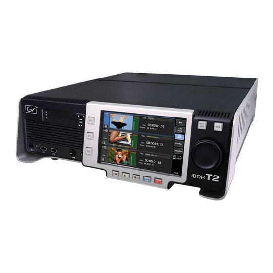
Part names and functions KOTRON Front Panel Layout (2009/8/18) Part names and functions Front panel DVD-ROM drive Touch screen LCD Control buttons Control buttons USB ports Headphone jack Control buttons Jog/Shuttle Power switch Volume control IEEE1394 port Displays the T2 screens. By touching on the items displayed on screen, T2 Touch screen LCD can be operated. -
Page 16: Control Buttons
KOTRON Front Panel Layout (2009/8/18) Section 2 ― Setup Control buttons Shuttle/Jog button Jog/Shuttle VAR button R1 button P1 button P2 button Rew button FF button Rec button Stop button Play button R1 button Switches the Recorder channel to active. P1 button Switches the Player1 channel to active. -
Page 17: Rear Panel
Part names and functions Rear panel Analog audio I/O section P2 output section Main power switch AC Power inlet (3 pin) P1 output section R1 input secttion IEEE1394 MONITOR Serial port GPI I/O Monitor port USB (2.0) REF IN REMOTE RS422 Mouse port (PS/2) Sound Keyboard port (PS/2) -
Page 18: Analog Audio I/O Section
Section 2 ― Setup Analog audio I/O section Used for audio input to the R1 channel. R1 – CH1 Balanced audio input. R1 – CH2 XLR-3-31x2 (CH1-2) Used for audio output from the P1 channel. P1 – CH1 Balanced audio output. P1 –... -
Page 19: P1/P2 Output Section
Part names and functions P1/P2 output section Used for LTC (timecode) output. AES/EBU Used for digital audio (AES/EBU) output. CMPST Used for Composite output. DVI-I Used for DVI-I output (for DVI, RGB, YPbPr). Used for SDI output. MONITOR Used for monitor output (Composite). Note The YPbPr signal is input/output via analog RGB pins on the DVI-I port. -
Page 20: Start-Up And Shutdown
Section 2 ― Setup KOTRON Start-up and shutdown Start-up The following procedure is to start-up the T2. 1. Switch the Main power switch on the rear panel to the on position, and turn the Power switch on the front panel ON. Power switch 2. T2 starts up and the 3ch View screen appears on the touch screen LCD. 3ch View T2 ― User Manual ― Workstation mode ―... -
Page 21: Switching To The Workstation Mode
Switching to the Workstation mode When the T2 starts up, it is running in the Front Panel mode by default. To switch it to the Workstation mode, perform the following procedure. 1. O n the PC monitor connected to the T2, choose Switch to Workstation mode from the System menu. * T o switch back to the Front Panel mode, touch the touch screen LCD screen, or choose Switch to Front Panel Mode from the System menu on the PC monitor. Shutdown The following procedure is to shutdown the T2. 1. Choose System - Exit. -
Page 22: Hardware Settings
Section 2 ― Setup Hardware settings Clicking the Config button at the top right corner of the screen displayed in the Workstation mode, the System settings screen will open. Modify the settings according to your environment. Config button System settings Hardware settings The options you can choose from for the reference input method are External, Input and Internal. The sync status is displayed in the boxes below this button. Displays if the P1 channel is synchronized. -
Page 23: Network-1/Network-2 Settings
Hardware settings Network-1/Network-2 settings Obtain an IP address Check this option to obtain an IP address automatically via DHCP. automatically Establishes a local area connection by specifying an IP address, subnet mask and default gateway. IP address Specify an IP address. Use the following IP address Subnet mask Specify a subnet mask. -
Page 24: Miscellaneous Settings
Section 2 ― Setup Miscellaneous settings Choose between English and Japanese for the on-screen language. Language * Restarting the system is required to apply the setting. Specify either drop-frame or non-drop frame to be used. DF Mode Check this option to use Drop frame. Check this option to use Non-drop frame. -
Page 25: R1 Channel Settings
Hardware settings R1 channel settings Input Settings Input type Choose a type of video input. Input format Choose a format for the video input. Video Aspect Choose the aspect ratio for the SD input. Correct white peak Check this option to enable white peak correction. Format Specify the compression format. -
Page 26: Timecode & Remote Settings
Section 2 ― Setup Timecode & Remote settings Select Timecode Specify the format for the timecode from TC (LTC) and SDI (VITC). Choose the timecode to use for recording. External Uses the timecode from the external device. Record Timecode Internal-System time Uses the system clock. -
Page 27: P1/P2 Channel Settings
Hardware settings P1/P2 channel settings Video settings Format Specify the resolution and the frame rate for the output video. DVI option Choose a video resolution to use with DVI/RGB format for output. Output capability Displays available format with highlight. Aspect Specify the aspect ratio. -
Page 28: Monitor & Remote Settings
Section 2 ― Setup Monitor & Remote settings Specify the channel to use for monitor out, and specify if OSD (on-screen display) is enabled. Channel Monitor out Specify the channel to use for monitor out. Only P1 is available for P1 channel, while P1 and P2 for P2 channel. -
Page 29: Procamp Settings
Hardware settings ProcAmp settings Adjusts the Video gain. Video gain (Available only for Composite and SD Component) Adjusts the Chroma gain. Chroma gain (Available only for Composite and SD Component) Adjusts the Chroma phase. Chroma phase (Available only for Composite) Adjusts the Black level. -
Page 30: Gpi Settings
Section 2 ― Setup GPI settings Input settings GPI-Input Use the Previous and Next buttons to choose the GPI input trigger. Permits specification of the GPI input trigger settings. Channel Choose a channel to respond to the GPI input trigger. Action Specify the action caused by the trigger. -
Page 31: Output Settings
Hardware settings Output settings GPI-Output Use the Previous and Next buttons to choose the GPI output trigger. Permits specification of the GPI output trigger settings. Name Trigger Settings Specify the name of the trigger. Active Choose the GPI signal to activate from High and Low. T2 ... -
Page 32: Jog/Shuttle Settings
Section 2 ― Setup Jog/Shuttle settings Shuttle speed Choose the maximum shuttle speed, either 16x or 32x. Choose the playback speed in the Variable speed playback mode, between VAR setting 1/8, 1/4 and 1/2. T2 ― User Manual ― Workstation mode ―... -
Page 33: Workstation Mode
Section Workstation mode Overview In the Workstation mode, you can operate the T2 via the display monitor connected to the T2, using the mouse and the keyboard. Touching the touch screen LCD while the T2 is running in the Workstation mode, it's switched to the Front Panel mode. T2 screen modes and functions Channel part Bin/Transfer part Status bar Content List part T2 ― User Manual ― Workstation mode ―... -
Page 34: Menu Bar
Section 3 ― Workstation mode The Workstation screen consists of the following. • Menu bar • Status bar • Bin/Transfer part • Content List part • Channel part Menu bar System menu Choose this option to exit Workstation mode and switch the T2 to Front Panel Switch to Front Panel mode mode. -
Page 35: Status Bar
T2 screen modes and functions Status bar Operation mode Clock Display Mode button HDD capacity Switches the display mode between 3ch Display and Full Display of a Display Mode button channel. Operation mode Displays the current operation mode. HDD capacity Displays the estimated amount of time for recording. -
Page 36: Bin/Folder Part
Section 3 ― Workstation mode Bin/Folder part Bin folder Watch Folder button New Folder button Search button Folder/Transfer button Switches the screen between Bin folder screen and Transfer screen. New Folder button Creates a new Bin folder. Watch Folder button Enables/Disables the Watch folder. -
Page 37: Creating Watch Folder Screen
T2 screen modes and functions Creating Watch Folder screen By specifying the folder created on a data drive as a Watch folder, you can share it via FTP. The folder specified as a Watch folder is kept watched, and when media files are added to the folder, they will automatically be added to the Bin. (The media file will be moved to the specified media folder.) Target Bin Displays the Bin folder name to be used as a Watch folder. Specify the FTP user name and its password. User Name Input a user name. Password Input the password. -
Page 38: Search Key Options
Section 3 ― Workstation mode Search Key options Specifies the target folder for the search. Name Use this option to search by name. Use this option to search by created date or updated date (A – B, Before A, Date or After A). -
Page 39: Bin Folder - Right Click Menu
T2 screen modes and functions Bin folder – Right click menu Use this option to search clips or playlists, specifying keys (in the selected Search folder only). Duplicate Duplicates the Bin folder. Deletes the selected folder from the Bin and moves them to the Recycle Bin. Delete The contents (clip, playlist) of the folder will also be deleted. -
Page 40: Recyclebin - Folder - Right Click Menu
Section 3 ― Workstation mode RecycleBin – Folder – Right click menu Restores the folder to the original Bin. Restore When a playlist is restored, if the clips used in the playlist exist in the RecycleBin, the clips will also be restored. Deletes all the contents in the Recycle Bin. -
Page 41: Recyclebin - Clip/Playlist - Right Click Menu
T2 screen modes and functions RecycleBin – Clip/Playlist – Right click menu Restores the item to the original Bin, and then opens the Bin folder. Restore When a playlist is restored, if the clips used in the playlist exist in the RecycleBin, the clips will also be restored. -
Page 42: Search - Right Click Menu
Section 3 ― Workstation mode Search – Right click menu Change Criteria… Use this option to search with other criteria. Clear Use this option to clear the search result. Rename Use this option to change the name of the search result. T2 ... -
Page 43: Transfer Screen
T2 screen modes and functions Transfer screen Clicking the Transfer button at the top of the Bin folder part opens the Transfer screen that displays the transfer status (registered transfer jobs and their status). Folder/Transfer button Switches the screen between Bin folder screen and Transfer screen. Import button Displays the Import screen. Export button Displays the Export screen. Deletes the selected job. Clicking the button while transferring will stop the Delete button transfer. -
Page 44: Import Screen
Section 3 ― Workstation mode Import screen Source folder Source File list Import Clip list Destination Displays the source folder that the contents are imported from. Source folder Clicking the button on the left opens the parent folder. Source File list Lists the media files (and folders) stored in the source folder. -
Page 45: Export Screen
T2 screen modes and functions Export screen Source Clip list Export File list Source Bin folder Destination folder Displays the Bin folder that the contents are exported from. Source Bin folder Clicking the button on the left opens the Bin selection dialog to change the Bin folder. -
Page 46: Content List Part
Section 3 ― Workstation mode Content List part Displays the Content List. From the right-click menu, the display mode can be switched between Text mode and Icon mode (Large/Small). Text mode Icon mode Folder name Displays the folder name. Displays the thumbnail. The color of the frame can be chosen among 5 Thumbnail colors. -
Page 47: Thumbnail Icons
T2 screen modes and functions Thumbnail icons Used in Playlist Pairing Clip Lock Playlist Pairing icon Displayed on the clips/playlists that have been paired for the Sync mode. Lock icon Displayed on the clip/playlist that have been locked. Used in Playlist icon Displayed on the clip/playlist that have been used in a playlist. -
Page 48: Pairing Contents (For Sync Mode)
Section 3 ― Workstation mode Pairing contents (for sync mode) From the right-click menu, pairing of contents for the sync mode between P1 and P2 channels can be set. The paired items have Sync icon on their thumbnails. To cancel the pairing, choose one of the paired items, and choose Unpairing from the right-click menu. Requirements for pairing • Contents must be of the same type. (clip and clip or playlist and playlist). -
Page 49: Clip/Playlist - Right Click Menu
T2 screen modes and functions Clip/Playlist – Right click menu Load to P1 Loads the selected content to the P1 channel. *1 Load to P2 Loads the selected content to the P2 channel. *1 Insert to P1 Playlist Adds the selected content to the playlist loaded on the P1 channel. *1 Insert to P2 Playlist Adds the selected content to the playlist loaded on the P2 channel. -
Page 50: Channel Part
Section 3 ― Workstation mode Channel part The channel part has two display modes: 3ch Display and Full display. 3ch Display Full Display T2 ― User Manual ― Workstation mode ―... -
Page 51: 3Ch Display
T2 screen modes and functions 3ch Display Displays R1, P1 and P2 channels. Clicking of each channel will activate the channel. T2 ― User Manual ― Workstation mode ―... -
Page 52: R1 Channel
Section 3 ― Workstation mode R1 channel This channel is used to record the input signal. For details on the items shown on the screen, see Full Display – Recorder channel page. P1/P2 channel – Clip Player This channel is used to play a clip. For details on the items shown on the screen, see Full Display – Clip Player page. -
Page 53: P1/P2 Channel - Playlist Player
T2 screen modes and functions P1/P2 channel – Playlist Player This channel is used to play a playlist. For details on the items shown on the screen, see Full Display – Playlist Player page. T2 ― User Manual ― Workstation mode ―... -
Page 54: Full Display - Recorder Screen
Section 3 ― Workstation mode Full Display - Recorder screen On this screen, you can modify the settings for recording and/or execute the recording. When the capacity of the HDD becomes low, the HDD icon is displayed in red. In that case, a warning message appears at the beginning of the recording. Status Preview Setting buttons Control buttons Information Status Status Lock button Status Displays the status of the recording operation with a circular chart. Lock button Locks/Unlocks the channel. T2 ... -
Page 55: Preview
T2 screen modes and functions Preview Preview Audio level Status bar Preview Displays the preview for the input video. Audio level Displays the input audio level. Displays the current timecode. Elapsed Displays the elapsed recording time by timecode. Status bar Displays the recording status with a bar. -
Page 56: Control Buttons
Section 3 ― Workstation mode Control buttons Cue (IN) Cues the VTR to the existing IN point. (Available only in VTR mode) Cue (OUT) Cues the VTR to the existing OUT point. (Available only in VTR mode) Rew button Rewinds the VTR. (Available only in VTR mode) Previous Frame button Moves back frame by frame. -
Page 57: Information
T2 screen modes and functions Information Clip Input a clip name. Input tags. Displays the information including video size, frame rate, input type, source Format timecode (TC (LTC) / SDI (VITC) / INT), etc. VTR In Displays the timecode at the IN point. VTR Out Displays the timecode at the OUT point. -
Page 58: Modes And Functions Of Recording
Section 3 ― Workstation mode Modes and functions of recording See the following table for the recording modes and their functions. Crash Rec Fixed Length Rec *1 *1 Live *1 Available only when IN/OUT points are not set. • I n VTR mode, when both IN and OUT points are set, the range between the IN and OUT points will be recorded, controlling the VTR. • I n VTR mode, when only IN point is set, the recording starts from the specified IN point, controlling the VTR. (Recording must be stopped manually.) • A ccording to the type of the recording, the icon of the Rec button differs. -
Page 59: Full Display - Clipplayer
T2 screen modes and functions Full Display - ClipPlayer On this screen, you can modify the settings for clip playback and/or execute the playback. Status Preview Setting buttons Information Control buttons T2 ― User Manual ― Workstation mode ―... -
Page 60: Status
Section 3 ― Workstation mode Status Status Playback mode Lock button Status Displays the status of the playback operation with a circular chart. E to E Displays whether the E to E mode is enabled. When the E to E mode is enabled, the recorder channel audio and video inputs are switched to the player channel audio and video outputs when the player channel is in stop mode or when there is no clip loaded. -
Page 61: Preview
T2 screen modes and functions Preview Preview Audio level Scrub bar Playback speed Zoom button Preview Displays the video preview. Audio level Displays the output audio level. Displays the current timecode. Playback speed Displays the current playback speed (ratio). Remain Displays the remaining time by timecode. -
Page 62: Setting Buttons
Section 3 ― Workstation mode Setting buttons Unload button Switch mode button Switches the player mode between Clip player and Playlist player. Click this button to enable remote controls from the external device Remote button connected. Unload button Unloads the loaded clip. Control buttons Cue (IN) Cues to the existing IN point. -
Page 63: Information
T2 screen modes and functions Information Clip Displays the name of the loaded clip. Displays tags. You can also input tags. Mark In Displays the timecode at the IN point. Mark Out Displays the timecode at the OUT point. Displays the duration of the content between the IN-OUT points by timecode. Click the Set button to update the IN/OUT points of the content according to Set button the existing IN/OUT points. -
Page 64: Preview - Right Click Menu
Section 3 ― Workstation mode Preview – Right click menu Set Thumbnail Frame Choose this option to use the current frame as a thumbnail. Loading clip from Bin To load a clip from the Bin, perform drag & drop, use the Bin menu, or double-click on a clip. -
Page 65: Sync Mode
T2 screen modes and functions Sync mode In the Sync mode, the clips that have been specified as paired clips in the Bin, can be loaded to the player channel. When a clip that has been paired is loaded onto the P1 channel, the other clip of the pair will automatically be loaded to the P2 channel. When the Sync mode is activated, if the output settings of the P1 and P2 channels differ, the settings on the P2 channel are automatically changed so as to match those of the P1. The E to E mode cannot be simultaneously activated. In the Sync mode, only playback operations are available. Marking IN/ OUT points or creating sub-clips is not available. * I f the duration of the contents differs between P1 and P2 channels, the playback operations will be performed according to the P1 channel. (P1 channel is the master channel.) When the content loaded on the P2 channel is shorter, the final frame remains displayed. T2 ... -
Page 66: Full Display - Playlistplayer
Section 3 ― Workstation mode Full Display - PlaylistPlayer In this screen, you can modify the playback settings for the playlist and/or execute the playback. The Event List will be automatically scrolled so that the clip being played is shown on screen. To enable/disable the auto-scroll for the Event List, click the Config button, open the Miscellaneous tab and change the Playlist AutoScroll setting (Default: ON). Operation buttons Preview Setting buttons Information Status Event List T2 ― User Manual ― Workstation mode ―... -
Page 67: Status
T2 screen modes and functions Status Status Playback mode Lock button Status Displays the status of the playback operation with a circular chart. E to E Displays whether the E to E mode is enabled. When the E to E mode is enabled, the recorder channel audio and video inputs are switched to the player channel audio and video outputs when the player channel is in stop mode or when there is no playlist loaded. -
Page 68: Preview
Section 3 ― Workstation mode Preview Preview Audio level Scrub bar Playback speed Zoom button Preview Displays the video preview. Displays the current timecode. Playback speed Displays the current playback speed (ratio). Remain Displays the remaining time by timecode. Scrub bar Displays the current position and the IN/OUT points. -
Page 69: Setting Buttons
T2 screen modes and functions Setting buttons Unload button Switch Mode button Switches the player mode between Clip player and Playlist player. Click this button to enable remote controls from the external device Remote button connected. Unload button Unloads the loaded playlist. Operation buttons Cue (IN) Cues to the top frame of the current event. -
Page 70: Information
Section 3 ― Workstation mode Information Playlist Displays the name of the loaded playlist. Displays tags. You can also input tags. Length Displays the total length o the playlist. Event Displays the name of the event being played. Displays the timecode at the IN point of the event being played. Displays the timecode at the OUT point of the event being played. -
Page 71: Event List
T2 screen modes and functions Event List Displays the list of the registered events and the playback status. Lists the events on the playlist. Event List On the thumbnail of each event, icons for identifying its effect are displayed, if any. * If the End Effect (Pause, Loop) is set on the final event of the playlist, the loop setting on the channel is ignored, and the specified End Effect takes precedence. -
Page 72: Event List - Right Click Menu
Section 3 ― Workstation mode Event List – Right click menu Copy opies the selected event (copies it to clipboard). Paste Pastes the content copied to clipboard. Delete Deletes the events from the Event List. Rename Changes the name of the selected event. Undo Undoes the previous editing operation. -
Page 73: Preview - Right Click Menu
T2 screen modes and functions Preview – Right click menu Choose this option to use the current frame as the thumbnail of the Set Thumbnail Frame current event. T2 ― User Manual ― Workstation mode ―... -
Page 74: Thumbnail Icons
Section 3 ― Workstation mode Thumbnail icons Fade Out icon Loop icon Pause icon Fade In icon Fade in icon Displayed on the contents where Fade In is set. Fade out icon Displayed on the contents where Fade Out is set. Pause icon Displayed on the contents where Pause is set for the End Effect. -
Page 75: Audio Level
T2 screen modes and functions Audio Level Clicking on the audio level area (arrow symbol) opens the Audio Level meter. LED level Gain slider Scale Monitor Channel Switches the display scale. Scale PEAK0 : -60dB to 0dB (Displays so that the maximum volume as 0dB: dBFS) REF0 : -40dB to +20dB (Displays the standard level (Headroom) as 0dB) LED level Displays the audio level (peak meter). -
Page 76: Properties Screen
Section 3 ― Workstation mode Properties screen Clip properties Clip Info tab Clip Displays the clip name. The clip name can be changed in this screen. Displays the name of the Bin folder where the clip is registered. Video Format Displays the video format. -
Page 77: Media Info Tab
Properties screen Media Info tab Location Displays the file name and the file path for the media file. Displays the number of the playlists that refer to the media file. Click the Reference View button to display the clips/playlists that refer to the media file. Size Displays the size of the media file. -
Page 78: Timecode Tab
Section 3 ― Workstation mode Timecode tab Specifies the method to change the timecode. Source Replace timecode media with Check this option to replace with the timecode for the source. Specify Start Time Check this option to specify the starting timecode, and specify the value. T2 ... -
Page 79: Playlist Properties
Properties screen Playlist properties Playlist Info tab Playlist Displays the playlist name. The playlist name can be changed on this screen. Displays the name of the Bin folder where the playlist is registered. Playlist Length Displays the duration of the playlist. Events Displays the number of events registered on the playlist. -
Page 80: Timecode Tab
Section 3 ― Workstation mode Timecode tab Start timecode at Check this option to specify the starting timecode, and specify the value. T2 ― User Manual ― Workstation mode ―... -
Page 81: All Events Tab
Properties screen All Events tab In this tab, the settings for all the events registered on the playlist can be modified globally. Check this option to change the start effect of the events. Remove all start effects Removes the start effects from all the events. Add start effect to every event Adds start effects to all the events. Fade In Change start effects Adds fade in to all the events. - Page 82 Section 3 ― Workstation mode Check this option to change the end effect of the events. Remove all end effects Removes the end effects from all the events. Add end effect to every event Adds end effects to all the events. Fade Out Adds fade out to all the events.
-
Page 83: Event Properties
Properties screen Event properties Event Info tab Event Displays the event name. The event name can be changed on this screen. Event In Displays the timecode at the IN point. Event Out Displays the timecode at the OUT point. Duration Displays the duration of the event. -
Page 84: Gpi Tab
Section 3 ― Workstation mode GPI tab Trigger GPI Choose the GPI trigger to specify setting. Start of Event Check this option to set the start of an event as a trigger. End of Event Check this option to set the end of an event as a trigger. Check this option to set a certain point from the top of an event as a trigger, Start plus and then specify the value. -
Page 85: Start Effect Tab
Properties screen Start Effect tab Check this option to add the fade in effect to the chosen event, and choose the effect. • Fade in (from black) ....Adds the fade in starting from a black Fade In screen. • Fade in (from white) .... -
Page 86: End Effect Tab
Section 3 ― Workstation mode End Effect tab Check this option to add the fade out effect to the chosen event, and choose the effect. • Fade out (to black) ....Adds the fade out ending with a black Fade Out screen. -
Page 87: Log Level Setting
Log Level Setting Log Level Setting Select a log level on this screen. Choose the type of the operation log. Error Only error logs are output. Warning + Error Operation Log Warning and error logs are output. Information + Warning + Error Information, warning and error logs are output. All the logs are output. -
Page 88: Log
Section 3 ― Workstation mode This screen displays the logs. Switch Log buttons Operation/Process list Log list Switch Log buttons Choose the log to display between Operation Log and Process Log. Operation/Process list Lists the operations/processes. Log list Lists the logs. Description Displays the description of the log. T2 ... -
Page 89: Appendix
Section APPENDIX T2 ― User Manual ― Workstation mode ―... -
Page 90: T2 Hardware Specifications
Mini DIN 6pin x2 PC interface Display Analog RGB D-SUB 15pin x1 Serial RS232C D-SUB 9pin x1 (Not used) RJ-45 Network connector x2, 10BASE-T/100BASE-TX/1000BASE-T Sound Stereo mini jack x6 (Not used) DVD-ROM x1 Removable media 2.5 inched removable drive bay x1 (RAID/SSD model) -
Page 91: Supported Resolutions
Supported resolutions Supported resolutions Conversion mode for PC Available Output to R1 input, REF input signal Profile Available format for loading video port monitor for Sync mode DVI-A DVI-D (RGB) 720×486 59.94i 720×486 59.94i 720×480 59.94i (DVD) Component × × NTSC 720×480 59.94i 720×480 59.94i (DV) -
Page 92: Gpi I/O Connector Pinouts
Section 4 ― APPENDIX GPI I/O connector pinouts Signal Signal Output 1 Input 1 Output 2 Input 2 Output 3 Input 3 Output 4 Input 4 Output 5 Input 5 Output 6 Input 6 Common Ground SHELL Common Ground Note T2 iDDR software supports outputs 1-6 and inputs 1-6 only.
Need help?
Do you have a question about the T and is the answer not in the manual?
Questions and answers