GRASS VALLEY KARRERA K-FRAME Installation & Service Manual
Video production center
Hide thumbs
Also See for KARRERA K-FRAME:
- User manual (410 pages) ,
- Installation & service manua (290 pages)
Table of Contents
Advertisement
Quick Links
Download this manual
See also:
User Manual
Advertisement
Table of Contents

Related Manuals for GRASS VALLEY KARRERA K-FRAME


Summary of Contents for GRASS VALLEY KARRERA K-FRAME
- Page 1 KARRERA K-FRAME VIDEO PRODUCTION CENTER Installation & Service Manual Software Version 7.0 071888004 JULY 2014...
- Page 2 CERTIFICATE Certificate Number: 510040.001 The Quality System of: Grass Valley USA, LLC and its Grass Valley Affiliates Headquarters: 400 Providence Mine Road 15655 SW Greystone Ct. Nevada City, CA 95945 Beaverton, OR 97006 United States United States Kapittelweg 10 2300 So. Decker Lake Blvd.
- Page 3 KARRERA K-FRAME VIDEO PRODUCTION CENTER Installation & Service Manual Software Version 7.0 071888004 JULY 2014...
- Page 4 Benelux/Belgium: +32 (0) 2 334 90 30 Benelux/Netherlands: +31 (0) 35 62 38 42 1 N. Europe: +45 45 96 88 70 Germany, Austria, Eastern Europe: +49 6150 104 444 UK, Ireland, Israel: +44 118 923 0499 Copyright © Grass Valley USA, LLC. All rights reserved. This product may be covered by one or more U.S. and foreign patents.
-
Page 5: Table Of Contents
2-ME Karrera Control Panel Installation ........KARRERA K-FRAME — Installation & Service Manual... - Page 6 Optional Local Aux Panel Cabling ........KARRERA K-FRAME — Installation & Service Manual...
- Page 7 Karrera K-Frame System Names ........
- Page 8 Karrera K-Frame System Preparation ....... Karrera K-Frame Configuration ........
- Page 9 Karrera K-Frame Drive Access ........
- Page 10 Grass Valley Web Site ........
- Page 11 Introduction ............Grass Valley Switcher Device Monitoring by SNMP.....
- Page 12 Contents KARRERA K-FRAME — Installation & Service Manual...
-
Page 13: Preface
Other Documentation The Switcher Products Protocols Manual is available for developers and soft- ware engineers to use to design interfaces to the Karrera K-Frame system. The K-Frame Ethernet Tally is a proprietary protocol that provides all of the switcher status information required to calculate the Tally state of the... - Page 14 The K-Frame Ethernet Tally Software Development Kit (SDK) is available to approved vendors who need to interface with the Ethernet Tally system of the K-Frame. Contact Grass Valley Product Management for more information on this SDK. The KSP Graphical User Interface Instruction Manual provides information,...
-
Page 15: Safety Summary
DANGER the marking. — A personal injury hazard exists but is not immediately acces- WARNING sible as you read the marking. — A hazard to property, product, and other equipment is present. CAUTION KARRERA K-FRAME — Installation & Service Manual... -
Page 16: Symbols On The Product
— Prior to servicing, remove jewelry such as rings, watches, Remove jewelry and other metallic objects. — Do not touch exposed connections, components or Avoid exposed circuitry circuitry when power is present. KARRERA K-FRAME — Installation & Service Manual... -
Page 17: Cautions
Use anti-static procedures, equipment and surfaces during servicing. — If you suspect product damage Do not operate with suspected equipment failure or equipment failure, have the equipment inspected by qualified service personnel. KARRERA K-FRAME — Installation & Service Manual... - Page 18 (ASICS). As a result, circuit board repair at the component level is very difficult in the field, if not impossible. For war- ranty compliance, do not troubleshoot systems beyond the board level. KARRERA K-FRAME — Installation & Service Manual...
-
Page 19: Sicherheit - Überblick
— Wenn Sie diesen Begriff lesen, besteht ein unmittelbares Verletzu- GEFAHR ngsrisiko. — Wenn Sie diesen Begriff lesen, besteht ein mittelbares Verletzu- WARNUNG ngsrisiko. — Es besteht ein Risiko für Objekte in der Umgebung, den Mixer VORSICHT selbst oder andere Ausrüstungskomponenten. KARRERA K-FRAME — Installation & Service Manual... - Page 20 — Führen Sie interne Servicearbeiten nur aus, wenn eine weitere Person anwesend ist, die erste Hilfe leisten und Wiederbelebungsmaßnahmen einleiten kann. — Legen Sie vor Servicearbeiten Schmuck wie Ringe, Schmuck abnehmen Uhren und andere metallische Objekte ab. KARRERA K-FRAME — Installation & Service Manual...
- Page 21 — Durch das unbefugte Öffnen wird die Garantie ungültig. Gerät nicht öffnen — Betreiben Sie das Gerät nicht an einer Richtige Spannungsquelle verwenden Spannungsquelle, die eine höhere Spannung liefert als in den Spezifika- tionen für dieses Produkt angegeben. KARRERA K-FRAME — Installation & Service Manual...
- Page 22 Hersteller empfohlenen Typs aus. Entsorgen Sie gebrauchte Batterien entsprechend den Anweisungen des Batterieherstellers. Das Gerät enthält keine Teile, die vom Benutzer gewartet werden können. Wenden Sie sich bei Problemen bitte an den nächsten Händler. KARRERA K-FRAME — Installation & Service Manual...
-
Page 23: Consignes De Sécurité
La signalétique suivante peut être apposée sur le produit: — risque de danger imminent pour l’utilisateur. DANGER — Risque de danger non imminent pour l’utilisateur. AVERTISSEMENT — Risque d’endommagement du produit, des installations MISE EN GARDE ou des autres équipements. KARRERA K-FRAME — Installation & Service Manual... - Page 24 — Ne réalisez pas une interven- Ne procédez pas seul à une intervention d’entretien tion d’entretien interne sur ce produit si une personne n’est pas présente pour fournir les premiers soins en cas d’accident. KARRERA K-FRAME — Installation & Service Manual...
- Page 25 — Ne branchez pas ce produit à une Utilisez la source d’alimentation adéquate source d’alimentation qui utilise une tension supérieure à la tension nomi- nale spécifiée pour ce produit. KARRERA K-FRAME — Installation & Service Manual...
- Page 26 Cette unité ne contient aucune partie qui peut faire l’objet d’un entretien par l’utilisateur. Si un problème survient, veuillez contacter votre distribu- teur local. KARRERA K-FRAME — Installation & Service Manual...
-
Page 27: Regulatory Notices
Changes or modifications not expressly approved by Grass Valley Group can affect emission compliance and could void the user’s authority to operate this equipment. -
Page 28: Canadian Certified Power Cords
Amendment 1: 2009/12/17. CAN C22.2, No. 60950 C22.2 #60950-1 Issue 2007/03/01 Ed. 2 Information Technology Equipment-Safety-Part 1 General Requirements. EN60950 Safety of Information Technology Equipment, including Electrical Busi- ness Equipment. 2006/95/EC Low Voltage Directive KARRERA K-FRAME — Installation & Service Manual... - Page 29 EN 61000-4-5: Power Line Surge EN 61000-4-6: Conducted RF Immunity Radiated Magnetic Field Immunity US FCC Class A CISPR Pub. 22 (1985) Canada FCC Industry Canada ICES-003 Australia & New Zealand: AS/NZS 3548 KARRERA K-FRAME — Installation & Service Manual...
- Page 30 Regulatory Notices KARRERA K-FRAME — Installation & Service Manual...
-
Page 31: Section 1 - Introduction
Section Introduction Overview The Grass Valley K-Frame family of multi-format digital production switchers provides powerful, ground-breaking features designed to meet the widest range of requirements for live studio, mobile, and post-produc- tion applications. The K-Frame Video Processor is the heart of the system, providing exten- sive video switching and signal processing capabilities. -
Page 32: K-Frame Video Processor
K-Frame Video Processor The K-Frame Video Processor is available in two sizes (Figure 1). The number of licensed boards present in the frame determines the number of KARRERA K-FRAME — Installation & Service Manual... -
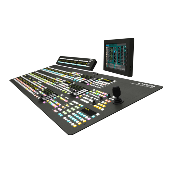
Page 33: K-Frame Control Surfaces
Karrera 3-ME 35 Control Panel Menu Panel Articulated Optional Touch Screen Karrera Menu Panel with Fanless PC Figure 3. Karrera 2-ME 25 Control Surface Karrera Menu on PC Karrera 2-ME 25 Control Panel (Customer Supplied PC) KARRERA K-FRAME — Installation & Service Manual... -
Page 34: Touch Screen Menu Panel Option
USB ports, two on the right side edge of the panel and two on the back for keyboard and mouse (wired or wireless are supported). A fanless PC, running Windows OS, is available which mounts behind the Menu Panel. KARRERA K-FRAME — Installation & Service Manual... -
Page 35: Soft Panel (Ksp) Option
The Menu application software provided with every K-Frame system can be run on a standard PC. This software accesses all the system’s function- ality, permitting mouse and keyboard control from a laptop, or remote control from any location on the network. KARRERA K-FRAME — Installation & Service Manual... -
Page 36: K-Frame System Examples
A K-Frame system can be subdivided into two suites, if desired, each of which can have two control surfaces. Hardware resources in the Video Pro- cessor Frame can be assigned to an individual suite during configuration, essentially creating two separate switchers sharing one K-Frame (Figure KARRERA K-FRAME — Installation & Service Manual... -
Page 37: Supported Control Protocols
• Serial BVW-75 for VTR control • Odetics protocol for VTR control • AMP (advanced media protocol) for Profile PVS, Profile XP Media Plat- form, K2, M-Series, Turbo iDDR, and T2 iDDR systems over Ethernet KARRERA K-FRAME — Installation & Service Manual... - Page 38 (Trinix/Trinix NXT, Venus™, Triton™, and third-party routers; Jupiter and Encore router control systems) • Tally (contact closure) • K-Frame Ethernet Tally protocol • Ethernet CPL to control Grass Valley external remote AUX Panels • Grass Valley Editor protocol • SNMP system monitoring • Serial and Ethernet VDCP •...
-
Page 39: Section 2 - Control Surface Installation
510.0 mm 3.3 in. 3.8 mm 20.1 in. 0.15 in. 55.1 mm 172.6 mm 2.2 in. 6.8 in. 482.6 mm 1413.5 mm 19.0 in. 55.6 in. 1440.6 mm 56.7 in. 510.0 mm 20.1 in. KARRERA K-FRAME — Installation & Service Manual... - Page 40 Figure 10. 3-ME Karrera Control Panel Rear Connections 12 Volt DC Out Ethernet USB* VGA* Aux Panel Control Cooling Fan Air Exhaust AC Power (not Ethernet) Air Intake * Reserved for maintenance use KARRERA K-FRAME — Installation & Service Manual...
-
Page 41: 2-Me Karrera Control Panel Installation
12.4 in. 575.0 mm 313.7 mm 22.7 in. 13.9 in. 454.8 mm 665.1 mm 26.2 in. 17.9 in. 1221.7 mm 48.1 in. 335.3 mm 2ME Cutout Dimensions 13.2 in. 1223.7 mm 48.2 in. KARRERA K-FRAME — Installation & Service Manual... -
Page 42: 2-Me Compact Karrera Control Panel Installation
4 mm 20.1 in. 0.5 in. 0.5 in. 0.14 in. 55 mm 173 mm 2.2 in. 6.8 in. 483 mm 982 mm 19.0 in. 38.7 in. 1010 mm 39.8 in. 510.0 mm 20.1 in. KARRERA K-FRAME — Installation & Service Manual... - Page 43 Figure 16. 2-ME Compact Karrera Control Panel Rear Connections 12 Volt DC Out Ethernet USB* VGA* Aux Panel Control Cooling Fan Air Exhaust AC Power (not Ethernet) Air Intake * Reserved for maintenance use KARRERA K-FRAME — Installation & Service Manual...
-
Page 44: Karrera Menu On User Pc Installation
Boot Camp partition or as a VM), and the Windows environment will need to be configured (including I/O device access, IP addresses, etc.). When a working Windows environment exists on the Mac, the Grass Valley Switcher Installer program can be used to install the Karrera Menu appli- cation into the Mac’s Windows environment, and the application can... -
Page 45: Menu On User Pc Software Installation
Menu on User PC Software Installation Karrera Menu Panel software is included on the Karrera Software USB stick, and is installed using the standard Grass Valley Switcher software installation process. The Karrera Menu application requires Microsoft .NET Framework software, which is also included on the USB stick. -
Page 46: Menu Panel Dimensions
129.4 mm 128.4 mm 3.84 in. 5.09 in. 5.06 in. 70.6 mm 2.78 in. 40.6 mm 1.60 in. 97.5 mm 3.84 in. 171.9 mm 170.9 mm 6.77 in. 6.73 in. 245.9 mm 9.68 in. KARRERA K-FRAME — Installation & Service Manual... -
Page 47: Menu Panel Connectors
Menu Panel chassis. Mounting the panel free-standing with the artic- ulated arm allows maximum air movement, and is the preferred installa- tion method. If an alternative method is used, ensure that all vents are unobstructed and adequate airflow is available. KARRERA K-FRAME — Installation & Service Manual... -
Page 48: Fanless Pc Dimensions And Connectors
USB 2.0 Headphone Power Hard Disk Reset Power Mic Input 1394 Port Port On/Off Figure 21. Fanless PC Rear Connectors DVI-D Audio Power Serial PS/2 Ports USB 2.0 Line Out Input Port Port Ethernet KARRERA K-FRAME — Installation & Service Manual... -
Page 49: Menu Panel Articulated Arm Installation
The supplied articulated arm is equipped with a flex-mount system, per- mitting a variety of mounting options (table-top, wall mount, etc.). See the documentation provided with the articulated arm for specific installation instructions. KARRERA K-FRAME — Installation & Service Manual... -
Page 50: Menu Panel Hardware Installation With Articulated Arm
For flat mounting directly to a vertical surface without using the articulated arm, two #10 screw sized washers (2.5 mm/0.10 in. thick) can be used at the lower two “U” bracket screw locations. KARRERA K-FRAME — Installation & Service Manual... -
Page 51: Optional Local Aux Panel Installation
445 mm 227 mm 158.6 mm 45 mm 17.5 in. 8.9 in. 3.1 in. 6.2 in. 122 mm 1.8 in. 4.8 in. 793 mm 31.2 in. 800 mm 31.5 in. 162 mm 6.4 in. KARRERA K-FRAME — Installation & Service Manual... -
Page 52: Local Aux 25 Panel Dimensions
2.1 in. 2.8 in. 32 mm 16 mm 1.3 in. 0.6 in. 25 mm Dimensions are mirrored. 1 in. Local Aux 25 are the same 25 mm as measured from corners. 1 in. KARRERA K-FRAME — Installation & Service Manual... -
Page 53: Tabletop/Backsplash Cutout Installation
809 +/-1 mm Ear Overlap 31.9 +/-.04 in. 17 mm 0.7 in. 159 +/-1 mm Local Aux Panel Cutout 6.3 +/-.04 in. Local Aux 25 Panel Cutout 619 +/-1 mm 24.4 +/-.04 in. KARRERA K-FRAME — Installation & Service Manual... -
Page 54: Tabletop Bracket Installation: 2-Me And 3-Me Main Panels
514 mm 20.2 in. 705 mm 335 mm 27.8 13.2 in. 1224 mm 485 mm 48.2 in. 19.1 in. 2-ME Main Panel Cutout Dimensions 1416 mm 55.7 in. 3-ME Main Panel Cutout Dimensions KARRERA K-FRAME — Installation & Service Manual... -
Page 55: Tabletop Bracket Installation: 2-Me Compact Panel
6.5 in. 2 mm and Main Panel upper edge. 0.1 in. (right of cutout) 521 mm 20.5 in. 485 mm 19.1 in. 984 mm 38.7 in. 2ME Compact Main Panel Cutout Dimensions Figure 30. KARRERA K-FRAME — Installation & Service Manual... - Page 56 Section 2 — Control Surface Installation KARRERA K-FRAME — Installation & Service Manual...
-
Page 57: Section 3 - Frames Installation
K-Frame Video Processors require rear rack support. Cooling Requirements The maximum ambient temperature for a Karrera K-Frame chassis is 40- degrees C (104-degrees F) monitored at the air intake. Installing the frame in a closed or multi-unit rack assembly together with other units could increase the maximum ambient temperature for this unit. -
Page 58: 13-Ru Standard Video Processor
Mounting a K-Frame in a rack immediately below equipment that extends forward from the rack may not provide enough clearance to completely remove the K-Frame door. See 13-RU Standard Video Processor on page KARRERA K-FRAME — Installation & Service Manual... - Page 59 13-RU Standard Video Processor Figure 32. K-Frame 13-RU Dimensions (Top View) 442 mm 17.4 in. 566 mm 22.3 In. 602 mm 23.7 in. 37 mm 1.5 in. 483 mm 19.0 in. KARRERA K-FRAME — Installation & Service Manual...
- Page 60 Figure 33. K-Frame 13-RU Rack Mounting and Cooling Airflow Rear Rack Support Air Exhaust (Chassis Top) Rear Rack Support Intake (Chassis Bottom) Intake (Chassis Bottom) CAUTION K-Frame installations require the use of the provided rear rack supports. KARRERA K-FRAME — Installation & Service Manual...
- Page 61 Slots F18 - F11 Front Slots F6 - F1 (Reserved for future use. CAUTION The Video Processor front door must remain in place and closed during normal system operation to maintain maximum cooling efficiency. KARRERA K-FRAME — Installation & Service Manual...
- Page 62 (DC power in, Up to 8 modules Reference, Ethernet and Module 1 Serial ports) Module 8 DIAGNOSTIC MODE OUTPUT OUTPUT OUTPUT OUTPUT INPUT INPUT INPUT INPUT Rear Slots R1 - R10 Slots R11 - R18 KARRERA K-FRAME — Installation & Service Manual...
-
Page 63: 6-Ru Compact Video Processor
Mounting a K-Frame in a rack immediately below equipment that extends forward from the rack may not provide enough clearance to completely remove the K-Frame door. See 13-RU Standard Video Processor on page KARRERA K-FRAME — Installation & Service Manual... - Page 64 Section 3 — Frames Installation Figure 37. K-Frame 6-RU Dimensions (Top View 442 mm 17.4 in. 596 mm 22.0 In. 559 mm 23.5 in. 37 mm 1.5 in. 483 mm 19.0 in. KARRERA K-FRAME — Installation & Service Manual...
- Page 65 Front Slots F1 - F4 Slots F9 - F12 (Reserved for future use) CAUTION The Video Processor front door must remain in place and closed during normal system operation to maintain maximum cooling efficiency. KARRERA K-FRAME — Installation & Service Manual...
-
Page 66: K-Frame Controller Connections
(from Power Supply) SERIAL PORTS RS422/485 LINK/ACTIVITY OFF-10/AMBER-100/GREEN-1000 DC IN ANALOG REFERENCE IMAGE STORE Serial Ports (8) Image Store Ethernet Reference RS422/486 (data transfer) Illuminated LED indicates Port 1 is in diagnostic mode KARRERA K-FRAME — Installation & Service Manual... -
Page 67: K-Frame Power Supply Frame Installation
AC Input IEC C19 (3) (to K-Frame) 38 mm 1.5 in. 36 mm 45 mm 1.4 in. 1.8 in. 97 mm 79 mm 3.8 in. 3.1 in. 217 mm 159 mm 8.5 in. 6.3 in. KARRERA K-FRAME — Installation & Service Manual... -
Page 68: K-Frame Power Supply Frame Rack Placement
The K-Frame power supply frame is ideally rack mounted immediately above the Video Processor chassis. The power supply frame is then sup- ported by the lower chassis and eliminates the need for power supply rear rack supports (Figure 45). KARRERA K-FRAME — Installation & Service Manual... - Page 69 (Figure 46). If mounting in an alternative loca- tion, allow for the 34” DC interconnect cable length. Figure 46. Isolated K-Frame Power Supply Rack Installation Rear Rack Support Exhaust Rear Rack Support Intake KARRERA K-FRAME — Installation & Service Manual...
-
Page 70: K-Frame Power Supply Cooling
C13 style, to accommodate potentially higher currents. Cables provided with K-Frame systems are matched to the destination country’s standard. For example, in the USA C19 to NEMA 5-20P cables are provided (Figure 47). Figure 47. USA Power Cable Example KARRERA K-FRAME — Installation & Service Manual... -
Page 71: Low Line (120V) Operational Considerations
Most of the above is not an issue if high line (240V) operation is used. Since AC line currents are approximately half of those at low line, exceeding the current rating of a circuit should not be a problem. In areas where there is KARRERA K-FRAME — Installation & Service Manual... -
Page 72: Video Processor Door Removal Clearance
If mounted below equipment that extends forward from the rack, allow at least 24 mm (0.94 in.) of vertical clearance above the K-Frame to permit door removal. A flush design 1 RU blank filler panel can be used for clear- ance, if required. KARRERA K-FRAME — Installation & Service Manual... -
Page 73: Section 4 - System Cabling
CAUTION The facility network used for your K-Frame system (and other video produc- tion equipment) should be kept separate from any external network, to prevent network traffic from adversely affecting K-Frame system operation. KARRERA K-FRAME — Installation & Service Manual... -
Page 74: K-Frame Network Cabling
Section 4 — System Cabling K-Frame Network Cabling Network connections are required between the Karrera K-Frame Video Processor, Control Panel, and optional Menu Panel PC. K-Frame Ethernet Switch The Ethernet switch built into the K-Frame auto-detects speed and polarity, and is 10/100/1000 Mbps capable. Either straight-through or crossover Ethernet cabling can be used. -
Page 75: Control Panel Network Cabling
(MEs, eDPMs, external devices, etc.) can be assigned to each suite, creating two switchers with one K-Frame. Each suite can be sub- divided into two control surfaces. Each control surface is intended for use KARRERA K-FRAME — Installation & Service Manual... -
Page 76: Customer Supplied Ethernet Routers And Switches
This reduces network traffic on the K-Frame network and keeps it isolated. Any Ethernet switches added specifically for use with the K-Frame system should be 1000 Mbps capable for the most efficient opera- tion (see Table KARRERA K-FRAME — Installation & Service Manual... - Page 77 Using a 1000 Mbps Ethernet switch enhances Image Store transfer speeds. Switch Recommended. Configuration not required, but does not provide Unmanaged remote monitoring capability. May be used. Requires configuration, but offers remote monitoring Managed capability. KARRERA K-FRAME — Installation & Service Manual...
-
Page 78: Factory Default Network Settings
Five connections are required for the Touch Screen Menu option. If the articulated arm is used, some of these cables can be routed through chan- nels in the arm that have covers that click into place. KARRERA K-FRAME — Installation & Service Manual... -
Page 79: Optional Local Aux Panel Cabling
Com 3 to that front USB port. Optional Local Aux Panel Cabling The Karrera K-Frame Local Aux Panel is powered from the Karrera K- Frame Panel, using a 4-pin XLR cable. System control is provided using a RJ-45 connecting cable, which uses a proprietary communications protocol (not Ethernet). -
Page 80: Video Cabling
16 on each output module. Identical signals are present on each of the paired output connectors. All of the outputs carry the same video format, as determined by the standard selected and by the reference signals connected. KARRERA K-FRAME — Installation & Service Manual... -
Page 81: Matchdef And Setdef Format Conversion
Inputs must be within this range to be properly timed at the output. The calculation of the actual video delay of a specific input is the Nominal KARRERA K-FRAME — Installation & Service Manual... - Page 82 • Inputs that reach the switcher at the earliest point in the autotiming window (-B μs) will have a total delay equal to the Nominal Switcher Delay (A μs) plus the autotiming window range. This value is the Maximum Switcher Delay value (D μs). KARRERA K-FRAME — Installation & Service Manual...
-
Page 83: Timing Analyzer
Figure 54. Video Settings Menu, This analyzer reports the timing position of a selected source relative to the Karrera K-Frame internal sync generator. The source is selected with the upper right soft knob and data pad. The relative position of Analyzer Source that source is reported in lines and μs. -
Page 84: Time Zones And The Autotiming Window
Center of Time Zone 1 Center of Time Zone 5 Window Autotiming Range Autotiming Range Too Early for Time Zones 5 and 6 Too Late for Time Zone 1 Center of Autotiming Window KARRERA K-FRAME — Installation & Service Manual... -
Page 85: Clipstore Cabling
ClipStore (K2 Summit/Solo, Figure 48 on page 73). Connect an Ethernet cable from the Karrera K-Frame, either directly or through a ded- icated Ethernet switch, to the bottom left (of the four) 100BT/1000BT Ethernet ports on the Summit/Solo backplane. - Page 86 The ClipStore server (4-channel Summit/2-Channel Solo) can be connected directly to the frame (Figure 57). It is also possible to connect to the Clip- Store directly from a router and not use any switcher outputs. KARRERA K-FRAME — Installation & Service Manual...
- Page 87 Also, DAs (Distribution Amplifiers) can be used to distribute Karrera K- Frame Aux Bus output. The example in Figure 58 shows DAs being used for both the Video and Key Aux Bus outputs from the frame. KARRERA K-FRAME — Installation & Service Manual...
-
Page 88: Video Processor Frame Gpi/Tally Interface
The nominal contact rating specification for each relay is 1A, 60 V. Note A tally interface that communicates with third party devices over Ethernet is also available. Refer to the separate Switcher Products Protocols Manual for specific information. KARRERA K-FRAME — Installation & Service Manual... -
Page 89: Gpi And Tally Connections
GPI In pin and one of the two GPI In Com pins (1 and 34). Pins 1 and 34 of each connector is connected to ground (Figure 59). For applica- tions that span across more than one connector, only one ground (common) connection is required. KARRERA K-FRAME — Installation & Service Manual... -
Page 90: Tally/Gpi Outputs
This common or isolated bus scheme can extend across multiple connectors. For example, a situation may require two iso- lated common buses, half of the commons form the first common bus and the other half form the second common bus. KARRERA K-FRAME — Installation & Service Manual... - Page 91 The solid state relays are bidirectional; either polarity voltage can be applied. If the switcher GPI/Tally outputs are used to drive downstream DC relays, be sure to install diodes across the KARRERA K-FRAME — Installation & Service Manual...
-
Page 92: Pin Assignments
Pin 9 Pin 6 TxA (-) RxA (-) Chassis Ground Chassis Ground RS-232 Ports RS-232 serial ports are located on each processor board (Video Processor, Panel Processor, Menu PC), available for maintenance and diagnostics. KARRERA K-FRAME — Installation & Service Manual... -
Page 93: Gpi In, Tally, Gpi Out
GPI In 9-16 Tally 25-48 GPI Out 9-16 GPI In 17-24 Tally 49-72 GPI Out 17-24 GPI In 25-32 Tally 73-96 GPI Out 25 - 32 GPI In 33-40 Tally 97-120 GPI Out 33-40 KARRERA K-FRAME — Installation & Service Manual... - Page 94 GPIOut19Y GPIOut27AG GPIOut35AJ GPIOut4G GPIOut12Q GPIOut20Y GPIOut28AG GPIOut36AJ GPIOutComH GPIOutComR GPIOutComZ GPIOutComAH GPIOutComAK GPIOut5H GPIOut13R GPIOut21Z GPIOut29AH GPIOut37AK GPIOut6H GPIOut14R GPIOut22Z GPIOut30AH GPIOut38AK GPIOut7H GPIOut15R GPIOut23Z GPIOut31AH GPIOut39AK GPIOut8H GPIOut16R GPIOut24Z GPIOut32AH GPIOut40AK KARRERA K-FRAME — Installation & Service Manual...
-
Page 95: Section 5 - Basic Configuration
Section Basic Configuration Introduction This section provides basic system configuration information for the Karrera K-Frame Video Production Center. Refer to the Kayenne/Karrera K- Frame Release Notes for information specific to your current software ver- sion. Configuration Steps Karrera K-Frame basic system configuration includes the following steps: 1. -
Page 96: Karrera K-Frame Configuration Data
Karrera K-Frame system operation. When the Video Processor resets, these settings are read and enacted. Configuration settings can be saved to files and loaded back into the Karrera K-Frame system at a later time to restore those operational settings. -
Page 97: Gv Switcher Menu Application
The GV Switcher menu application is used to configure your Karrera K- Frame system. This application can run on a user supplied PC, using a mouse and keyboard, and can run on the optional Karrera K-Frame Touch Screen menu, allowing system operation by touching the screen. -
Page 98: Menu Top Line
• The center portion of the top line displays operations status messages. • The right portion of the top line is an operator notification area, where messages generated by the Karrera K-Frame system are displayed. Data Pads and Touch Buttons... -
Page 99: Data Pads And Soft Knobs
Note The optional eDPM system has its own set of operating menus, accessed by touching the eDPM button on the lower left. For basic Karrera K-Frame con- figuration be sure the SWR button is selected. System Power Up and Initialization The Karrera K-Frame Video Processor Frame, Control Panel, and menu application must be running for full system operation. -
Page 100: Power And Initialization Indications
Section 5 — Basic Configuration 2. The Karrera K-Frame Control Panel power switch is located inside the tub, near the center of the upper board. The two screws holding down the lid can be opened with a 1/4 turn using a coin or flat-blade screwdriver. -
Page 101: Default Karrera K-Frame System Communications
PC: • The Video Processor Frame must be powered up and running. • The IP address of the Karrera K-Frame Menu Panel must be set to be on the same network as the Video Processor Frame. • Ethenet cabling should connect the Control Panel to the Video Pro- cessor Frame, either directly or though an Ethernet switch. - Page 102 Menu Panel application, or Restart Now you can , make changes to the Image Store IP Address and Track Cancel DPOPs from Panel IP, and then do a single Menu Panel restart. KARRERA K-FRAME — Installation & Service Manual...
-
Page 103: Network Configuration
Menu Panel should be fully operational. Network Configuration IP Address Background Information Each device connected to any Ethernet network must have a unique IP address. An IP address has two components: the network address and the KARRERA K-FRAME — Installation & Service Manual... -
Page 104: Gateway Ip Addresses
Karrera K-Frame system components, or have multiple Karrera K-Frame systems on the same network cabling. For example, if more than one Karrera K-Frame system resides on the same network, the IP address of each additional Karrera K-Frame device must be changed before it is con- nected to the network. -
Page 105: Setting Ips With The K-Frame Switcher Installer Program
A mouse and keyboard is required to navigate through the K-Frame Installer program and enter IP numbers and system names. Standard USB devices can be connected to any of four available ports on the Karrera K-Frame Menu Panel. Karrera K-Frame System Names The K-Frame Installer program includes a hierarchy display of Karrera K- Frame system components. -
Page 106: Set Ip Procedure Using K-Frame Installer Program
Frames and Control Panels will be grouped under that name. If you have more than one Karrera K-Frame system, be sure to change the name of the Video Processor Frames so you can identify them easily. When each Frame has a unique name, the Control Panels configured with each Frame will be grouped with that system name. - Page 107 Reset Procedures on page 220 for details. CAUTION Changing the IP address of an operating Karrera K-Frame component can disrupt system communications until matching changes to the addresses other components use are made on those other devices. Registering new IP Node addresses may also be necessary.
-
Page 108: Other K-Frame Switcher Installer Program Functions
IP addresses. Set IP Procedure Using Device Web Pages You need to know the current IP address of the Karrera K-Frame Video Pro- cessor or Control Panel before you can change it using a Web browser, mouse and keyboard. - Page 109 The device will boot up with the new IP address. When a Video Processor Frame IP address has been changed, communica- tions will no longer occur with any Karrera K-Frame system devices that are configured to use the old frame IP address. You will need to go to each device and change the address they use to communicate with the Video Processor Frame.
-
Page 110: Changing Image Store Ip Address
Setting IPs with Device Web Pages on page 108 for more information. Changing Control Panel IP Addresses A Karrera K-Frame Control Panel’s IP address can be changed using various methods: • K-Frame Switcher Installer program (see Setting IPs with the K-Frame Switcher Installer Program on page 105). - Page 111 4. Use the keypad buttons to enter the new IP address values. When the new IP address has been entered, select (press (Figure 74). Enter Figure 74. Karrera K-Frame Panel IP Address Mode, Entering New IP Values Menu Panel IP Address ###.###.###.### Enter Cancel...
- Page 112 Section 5 — Basic Configuration CAUTION Changing the IP address of an operating Karrera K-Frame component can disrupt system communications until matching changes to the addresses other components use are made on those other devices. Re-registering IP Node addresses may also be necessary. See...
-
Page 113: Changing Menu Panel Ip Address
Remote Aux Panel. If more than one Remote Aux Panel will be used on your Karrera K-Frame system, you will need to change each panels’ IP addresses so none are duplicated, and this must be done before you connect them to the network. - Page 114 Section 5 — Basic Configuration Figure 78. Panel Description Screen 3. Click on . A Network Configuration screen similar to Figure 79 Network will appear, displaying the factory default settings. Figure 79. Panel Network Screen, Default Information KARRERA K-FRAME — Installation & Service Manual...
-
Page 115: Restoring The Default Ip Address
6. Disconnect the PC, and connect the Remote Aux Panel to the Karrera K- Frame system network. 7. Repeat this procedure on all the Remote Aux Panels to be used with your Karrera K-Frame system, entering a unique IP address for each Remote Aux Panel. Remote Aux Panel Registration on page 117 regarding additional config- uration steps required. -
Page 116: Menu Panel Registration
GV Switcher menu application Node Settings menus. Menu Panel Registration Registering the Karrera K-Frame Menu Panel (or PC running the GV Switcher menu application) with the Frame was described earlier (see Establishing Menu to Frame Communication on page 101). -
Page 117: Remote Aux Panel Registration
Figure 81. Remote Aux IP Network Menu 2. Touch an available set of buttons and enter an Aux Panel Name and IP address of each Aux Panel. 3. Identify the type of Remote Aux Panel (Single or Multi- Destination). KARRERA K-FRAME — Installation & Service Manual... -
Page 118: Control Panel Brightness Adjustment
(for example, to accommodate varying ambient room lighting levels). 1. Access the Karrera K-Frame Panel webpage, by entering its IP address in a web browser, then clicking on (Figure 82). -
Page 119: Lever Arm And Joystick Calibration
Adjustments on page 224. Engineering Setups Karrera K-Frame inputs and outputs are connected to the rear of the Video Processor Frame. These video signals need to be configured to your facility’s requirements. Engineering Setups defines Karrera K-Frame system component functionality and how it is cabled into a facility. Engi- neering setups are intended to be used and maintained by technical staff, and can be loaded and saved to disk. -
Page 120: Source Definition Inputs
Table 12. Standard K-Frame Source Definition Outputs Outputs Modular Outputs 1-16 17-32 33-48 49-64 65-68 73-76 81-84 89-92 69-72 77-80 85-88 93-96 Table 13. Compact K-Frame Source Definition Outputs Outputs Modular Outputs 1-16 17-32 65-68 73-76 69-72 77-80 KARRERA K-FRAME — Installation & Service Manual... -
Page 121: Source Definition Menu
Note The number of usable input connectors depends on the number of ME boards installed in the Karrera K-Frame Video Processing (24 inputs per board). KARRERA K-FRAME — Installation & Service Manual... -
Page 122: External Device Source Definition
Engineering names are entered in the Eng Setup Source Definition menu, as described above. Engineering source IDs are numeric only, and are avail- able on data pads and scroll knobs for quick selection. The Karrera K-Frame system also has logical IDs, that can be used for source patching, as explained later. -
Page 123: Name Display Hierarchy
). The same set of engi- Eng Setup Eng Login neering names will be used by both Karrera K-Frame suites, however. Name Display Hierarchy If a source’s engineering name is left blank, the Eng ID number will be used. If no alternative names are defined for that source, then that Eng ID number will appear on all the Karrera K-Frame system displays. - Page 124 When multiple names are created, try to keep the first four characters unique, and make different names for the same source similar for ease of recognition. KARRERA K-FRAME — Installation & Service Manual...
-
Page 125: Fixed Sources
• Eng Setup, Outputs menu Source Patch Feature The Karrera K-Frame system provides a way to map engineering source IDs to logical IDs, using the Source Patch feature. By default this mapping is one-to-one, but this feature can be used to quickly set up production ele- ments for use in a different facility. -
Page 126: Button Mapping
Tally and associations with external devices are based on engineering sources. Button Mapping After sources have been defined they can be mapped to Karrera K-Frame system Control Panel buttons. The Button Mapping menu (accessed by touching ) is used to map the sources... -
Page 127: Changing Output Assignments
Engineering Setups Changing Output Assignments The Outputs menu is used to change the Karrera K-Frame system output assignments. The current output assignments can be viewed in this menu. Press to access this menu (Figure 85). Eng Setup Outputs Figure 85. Outputs Menu The scrolling list of data pads along the left side of the screen shows the cur- rently assigned output for each listed module output connector. -
Page 128: Aux Bus Configuration
Aux Bus control, or using Remote Aux Panels delegated to control that Aux bus. The number of Aux buses on a Karrera K-Frame system varies, depending on how the physical outputs have been mapped. Any output that is not configured as Fixed or Switched Preview is available for use as an Aux bus. - Page 129 Video Only Aux Bus When the button is not selected, the Aux bus is configured as a Aux Bus Pair single video-only output (Figure 86). Figure 86. Output Assignments Menu, Video Only Aux Bus KARRERA K-FRAME — Installation & Service Manual...
-
Page 130: Me Viewer
(ME) pM source can be assigned one of six multiple signal arrangements, in User Setups/Suite Prefs. Assigning this source to a physical output connector permits viewing that arrangement of signals on a monitor. KARRERA K-FRAME — Installation & Service Manual... -
Page 131: Switcher Tally Configuration
The Switcher Tally menus also allow the user to map Engi- neering Sources to the tally relays. Up to 96 tally relay outputs are available on a Karrera K-Frame Video Processor, 24 for each installed Controller or ME board. Tally is recalculated and refreshed every field. -
Page 132: About Tally Systems
Section 5 — Basic Configuration Note Tally Contribution is an alternative electronic tally mechanism that can be assigned to a Karrera K-Frame Video Processor serial port. Refer to the sep- arate Grass Valley Switcher Protocols Manual for technical information. About Tally Systems In general, a tally system identifies which sources to the switcher contribute to the final picture at a selected point in the video chain. -
Page 133: Switcher Tally Calculator Menus
The Switcher Tally menus are used to select calculators, methods, and levels, name calculators, and assign items to Tributaries. Karrera K-Frame has six independently running tally calculators. For example, the system can calculate On Air tally independently for suite 1 and suite 2, and at the same time can calculate Look Ahead tally, and ME output tallies for three MEs. - Page 134 Groups Enabled calculator, by group letter (A, B, C, D, corresponding to Tally/GPI connec- tors 1-4 on the rear of the Karrera K-Frame Video Processor). To Enable a Tally Relay Group, it must first be turned on, using the button for Calc On that calculator.
- Page 135 2. Touch the button to open a keypad you can use to name Calc 1-4 Name that calculator. 3. Choose the button for the Karrera K-Frame suite that will use Suite 1-2 this calculator. 4. Touch a button on the right.
- Page 136 Use the Look Ahead Preview procedure above, but choose PGM/PST, ME, or Aux, on the left, and then select the desired bus in the center of the screen. Repeat for all the buses you wish to tally for that (Figure 92). KARRERA K-FRAME — Installation & Service Manual...
-
Page 137: Relay Assign Menu
The Relay Assign menu is used to assign the Tally Calculators to Relay Groups, and assign Engineering Sources to relays on the Video Processor Frame GPI/Tally connectors. Touch the Relay Assign tab to access the menu (Figure 93). KARRERA K-FRAME — Installation & Service Manual... - Page 138 Tally Relay Group Group. The A, B, C, and D Tally Groups correspond to Tally/GPI connec- tors 1 through 4 on the rear of the Karrera K-Frame Video Processor. - Assigns the Tally Calculators to the delegated Tally Calculation Enables Group.
-
Page 139: About Mv Green Tally Calculations For Multiviewer On-Air And Green
PST bus, in a typical configuration, communicating that those sources are in LAP and can transition to on-air next. 1. Select Eng Setup Switcher Tally 2. Select the button in the Tally System pane (upper right). MV Tally KARRERA K-FRAME — Installation & Service Manual... -
Page 140: Set Source Names With External Ethernet Tally
Frame that will modify any or all source names in the system, including the Engineering Names for each source. Additionally, the Control Panel, OLED, and Menu names for each logical source in each suite can be set externally. KARRERA K-FRAME — Installation & Service Manual... - Page 141 • Red—external Ethernet tally connection error 3. Select the Connection Status button to connect to the external Enable Ethernet tally client. 4. Enable the Source Name Control by selecting the button for the Enable external Ethernet tally connection. KARRERA K-FRAME — Installation & Service Manual...
-
Page 142: Clipstore Configuration
The NetConfig Network Configuration Tool is installed as part of the Karrera K-Frame software. Note Make note of the ClipStore IP Address, it will be used later to enable Clip- Stores as external devices later in the Karrera K-Frame configuration process. KARRERA K-FRAME — Installation & Service Manual... -
Page 143: Karrera K-Frame System Preparation
Karrera K-Frame Configuration Configuring ClipStore as a Node ClipStore must be configured as a node in the Eng Setup, Node Settings menu before the Karrera K-Frame system can communicate with the Summit/Solo ClipStore server. 1. Verify there is a valid network connection. - Page 144 Name for the source if desired. The following example demonstrates the configuration of a Summit with four ClipStore channels. In this example the physical BNC connections from the ClipStore to the K-Frame are Inputs 25-32. KARRERA K-FRAME — Installation & Service Manual...
- Page 145 6. Configure the Source Type: a. Touch the mode button in the Source Type pane (Figure 98). Device b. Touch the data pad, the External Device List is External Device displayed (Figure 98). KARRERA K-FRAME — Installation & Service Manual...
- Page 146 Source Type pane to select it. Direct 5. Give the ClipStore key input an Engineering Name if desired (CS-1K, Figure 99), by touching the data pad and entering the Engineering Name name in the pop-up keyboard. KARRERA K-FRAME — Installation & Service Manual...
- Page 147 Set the switcher outputs that are feeding into ClipStore. By selecting an Aux bus then touching one of the CS-1 through CS-4 enable buttons, those Aux bus outputs will be paired. In other words, if you select the output, then KARRERA K-FRAME — Installation & Service Manual...
- Page 148 Local Aux area and/or can be button mapped as desired. When acquiring CS channels in another suite, before reassigning CS chan- nels: 1. In the Outputs menu, deselect the CS channels to be acquired (Figure 100). KARRERA K-FRAME — Installation & Service Manual...
-
Page 149: Clipstore Config Menu
101). A dialog is displayed when this button is pressed (Figure 102), stating that all clips will be ejected as part of this oper- ation; keep this in mind if considering this operation during a broadcast. KARRERA K-FRAME — Installation & Service Manual... -
Page 150: Assigning Clipstore Channel Resources To A Suite
Eng Setup, Acquire Resources, Effects, Stores & Viewers menu (Figure 103). For information about acquiring suite resources, see the Divide Resources Between Suites on page 178. Figure 103. ClipStore Acquire Resources KARRERA K-FRAME — Installation & Service Manual... -
Page 151: Setting The Summit/Solo Ip Address
1. Disable the FBWF (File Based Write Filter) a. Click on the menu and navigate to Start All Programs Grass Valley b. Click on (top of list). Write Filter Utility The FBWF Manager is displayed (Figure 104). KARRERA K-FRAME — Installation & Service Manual... - Page 152 Section 5 — Basic Configuration Figure 104. FBWF Manager KARRERA K-FRAME — Installation & Service Manual...
- Page 153 Click e. At the reboot prompt, click (Figure 106). Figure 106. Reboot Prompt 2. Once the server has rebooted, enter your login and password. 3. Right-click on Network Places 4. Click Properties KARRERA K-FRAME — Installation & Service Manual...
- Page 154 7. Scroll down to “Internet Protocol (TCP/IP)” and click to highlight it (Figure 108). Figure 108. Control Team Properties—TCP/IP Disable/Enable Filter Settings 8. Click Properties The TCP/IP Properties Dialog is displayed (Figure 109). KARRERA K-FRAME — Installation & Service Manual...
-
Page 155: Camera Control With Ethernet Tally Configuration
142, Step 2. Reboot the ClipStore Summit/Solo server. Camera Control with Ethernet Tally Configuration The Karrera K-Frame system uses Ethernet to communicate with the LDK Connect Gateway (Figure 110). Some basic configuration is required in the Eng Setup menu. -
Page 156: Node Settings
Node Settings In the Eng Setup, Node Settings menu, enter a valid IP Address for the camera gateway and touch the Enable button. When connected, the LDK Connect LED will turn green (Figure 111). KARRERA K-FRAME — Installation & Service Manual... -
Page 157: Source Definitions
Engineering Setups Figure 111. Camera IP/Enable, Node Settings Menu Source Definitions To enable camera control from the Karrera K-Frame, the source is defined as a “Camera” type then assigned as a camera in the Eng Setup, Source Definition menu (Figure 112). - Page 158 Figure 112. Camera Source Type, Source Definition Menu 1. Touch the desired source in the Source List (Figure 112). 2. Set the Video Input and Key Mode (see the Karrera K-Frame User Manual for more information). 3. Touch the source type button in the Source Type pane...
-
Page 159: Acquire Resources
Camera resources are acquired in the Eng Setup, Acquire Resources, Camera Control menu (Figure 114). Camera resource acquisition is represented in the Camera Controls Acquired in Suite pane (Figure 114) in the Camera Controls menu as fol- lows: KARRERA K-FRAME — Installation & Service Manual... - Page 160 4. Touch the data pad of the desired suite. 5. Return to the Eng Setup, Acquire, Camera Control menu and touch the component buttons you wish to acquire to the suite. 6. Touch the button. Acquire Selected KARRERA K-FRAME — Installation & Service Manual...
-
Page 161: Switcher Ethernet Camera Tally
Engineering Setups Switcher Ethernet Camera Tally The Karrera K-Frame system provides a quickly connected, reliable, three color tally (Red, Yellow, and Green) via Ethernet to Grass Valley cameras (Figure 115). Figure 115. Switcher Tally LDK Camera Ethernet Menu Tally Calc Menus As with Switcher Tally, the LDK Camera Ethernet menu is used to select calculators, name calculators, and assign bus contributors to tributaries. - Page 162 The Color Assign menu is used to assign the Tally Calculators to the Tally Colors. Touch the Eng Setup, Switcher Tally, Color Assign menu tab to access this menu (Figure 116). Figure 116. Color Assign Menu KARRERA K-FRAME — Installation & Service Manual...
-
Page 163: User Setups
User Setups are intended primarily for operators, to allow them to cus- tomize their working environment. However, some settings affect basic system operation. The engineer in charge of a Karrera K-Frame system should create and save at least one default set of User Setups (Panel Prefs and Suite Prefs) so the system can be set to a known state. - Page 164 Source Filter numeric source name filter. Only source names that begin with the entered text will be displayed in the scrolling to the immediate left. • The button clears the source filter. Show All KARRERA K-FRAME — Installation & Service Manual...
-
Page 165: Suite Prefs
The Default Keyframe menu is accessed by touching User Setups Suite Prefs (Figure 119). Default Keyframe Figure 119. Default Keyframe Menu To Learn a Default Keyframe: 1. Setup the entire Control Panel to the desired state. KARRERA K-FRAME — Installation & Service Manual... -
Page 166: Configuration File Save And Load
Configuration File Save and Load Karrera K-Frame File Browser The Karrera K-Frame system has a file browser. You can browse through folders on the local Karrera K-Frame Menu hard disk, the Karrera K-Frame Video Processor, and the entire network file hierarchy of mapped drives. -
Page 167: File Storage Organization
Karrera K-Frame Drive Access The Karrera K-Frame File Operation menus can access directories located on the USB Memory Stick in the Video Processor Frame (System Storage) and the Menu Panel hard drive (Remote Storage). Local and network drives mapped on the Menu Panel’s Windows system are also accessible... -
Page 168: File Type Extensions
File Type Extensions Karrera K-Frame files are named by the user when saved, and this name appears below the icon in the browser. The extension for each system file type is listed in Table Table 15. -
Page 169: Eng Setup File Operations
Configuration File Save and Load Non-Karrera K-Frame generated file icons show the file name with exten- sion, and displays the extension letters in the icon. Eng Setup File Operations The Eng Setup, Save Load menu is used to save and load engineering setups information. -
Page 170: Utilities Pane
3. Touch the button. Load CAUTION The Load button immediately replaces information the Karrera K-Frame system is currently using with the selected file information. When configura- tion files are loaded, significant changes to system operation are possible. KARRERA K-FRAME — Installation & Service Manual... -
Page 171: Multiple Suite Resource Sharing
Multiple Suite Resource Sharing Multiple Suite Resource Sharing Introduction The Resource Sharing feature permits the allocation of Karrera K-Frame system resources between two suites. This allows independent system operation from multiple locations without conflict. Logical resource assignments allow the reuse of E-MEM effects in either suite regardless of which specific hardware resources were allocated. -
Page 172: Independent Resource Sharing
When one suite has acquired a resource, only the operator or group of operators in that suite will be able to control it. An example of independent sharing is splitting a 4-ME Karrera K-Frame system into two independent 2-ME switchers (Figure 123). -
Page 173: Control Surface
2-A, or 2-B Frame Control Surface A control surface is generally a group of panels which interact and provide a single user a unified work surface. An example of this type of control KARRERA K-FRAME — Installation & Service Manual... -
Page 174: Logical Aux Buses
Section 5 — Basic Configuration surface is a Control Panel and Menu Panel of a 4-ME Karrera K-Frame system. These panels combine to form a Technical Director’s (TD) control surface. Other Control Panel modules or additional Menu Panels can be added to a control surface. -
Page 175: Setting Up Resource Sharing
Setting Up Resource Sharing Preparation Your Karrera K-Frame system should first be fully operational. For new customers, an initial system configuration will be required. This basic setup will become the baseline for suite 1 operation. This includes having an Eng... -
Page 176: Configure Control Surfaces
Ports & Devices GPI Outputs • Editor Ports, if used, are permanently assigned for use by each suite Eng Setup Ports & Devices, Editor Ports • Switcher Tally ( Eng Setup Switcher Tally KARRERA K-FRAME — Installation & Service Manual... - Page 177 Each suite has its own, logical set of outputs that are identically numbered. Use the Suite 1 and Suite 2 buttons to assign them to a suite. Figure 126. PGM Output Assigned to Suite 2 KARRERA K-FRAME — Installation & Service Manual...
-
Page 178: Divide Resources Between Suites
Section 5 — Basic Configuration Divide Resources Between Suites Note Changes to Suites and Resource Sharing can have serious Karrera K-Frame system operation impacts that may not be completely obvious. For this reason, precautionary messages requiring a response are posted. - Page 179 3. To acquire installed DPM options, move available iDPM Channels from Available to Channels using the arrow keys (Figure 128). Any number of licensed iDPM channels can be acquired to the selected resource, or acquired as eDPMs using the Acquire Resources menu. KARRERA K-FRAME — Installation & Service Manual...
-
Page 180: Save Default Multi-Suite Engineering Setups File
Similar to Suite Prefs above, Panel Prefs files can be created and saved for each control surface, if you wish. For engineering troubleshooting pur- poses, you may be able to define and save a single Panel Prefs file for use on any control surface. KARRERA K-FRAME — Installation & Service Manual... -
Page 181: Delegate Stripes To Mes In Each Suite
Once configured with two suites, operators can work on each control surface completely independently from one another. Coordination will be required, however, to ensure the resources each operator needs are shared as necessary. KARRERA K-FRAME — Installation & Service Manual... -
Page 182: Engineering Login
Engineering Login A Karrera K-Frame system can be configured as two suites, with each suite having up to two control surfaces. The Eng Login menu is used to choose which suite and control surface the GV Switcher menu will interact with and control. -
Page 183: Setdef And Matchdef
SetDef and MatchDef Karrera K-Frame system resources can be allocated to each suite. By default all system resources are allocated to suite 1. See Multiple Suite Resource Sharing on page 171 for more information. Note Changing a menu’s identity in this way is temporary. Reloading the menu application or rebooting the Menu Panel will restore the Suite and Control Surface identity defined in the Node Settings Control Surfaces menu. -
Page 184: Setdef Output Conversion
MatchDef Input Conversion When MatchDef Mode is selected, the Modular I/O buttons report the current Mode, Engineering Name of the input, Suite 1 or 2 (S1 or S2), KARRERA K-FRAME — Installation & Service Manual... - Page 185 Cut are displayed, depending on the format selected. These controls are identical to those used for SetDef. The button behaves the same Sync/Scale as the SetDef button, but also employs frame sync circuitry. Scale KARRERA K-FRAME — Installation & Service Manual...
-
Page 186: Video Settings
Digital reference. This should only be used temporarily, for troubleshooting or initial system test, because an interruption of that input signal can cause Karrera K-Frame system problems. KARRERA K-FRAME — Installation & Service Manual... -
Page 187: Frame Operating Mode
Live Mode and Film Mode processing is exactly alike. When the K-Frame is set to a psf Frame Operating Mode, it uses “Live Mode” processing for smother internally generated motion, while retaining some “Film Look” aesthetics. KARRERA K-FRAME — Installation & Service Manual... -
Page 188: Other Settings
Command Processing These controls determine when commands (like source selections or the initiation of mixes or wipes) will be enacted by the Karrera K-Frame system (also known as field dominance). These controls can be useful for consis- tent match frame editing. -
Page 189: Default Idpm Crop
SMPTE RP-187 establishes recommended practices for standard image sizes (production aperture, clean aperture). If a facility conforms to these practices, the Karrera K-Frame system default values will be correct and no adjustment should be necessary. Changing the default crops is not recom- mended, unless absolutely necessary. -
Page 190: Frame Suite Nodes & Id Menu
Note Do not change device or suite names unnecessarily, as this could cause con- fusion to other Karrera K-Frame system users. Mapping Logical Remote Aux Panels The Remote Aux Logical Map menu... - Page 191 1. Highlight a Panel Delegation button at the top of the screen. 2. Touch one of the Logical Aux Buses buttons on the lower screen. That Aux Bus will then be selected when that Remote Aux Delegation button is pressed on that panel. KARRERA K-FRAME — Installation & Service Manual...
-
Page 192: Remote Aux Button Mapping
• The data pad and scroll knob on the upper right can be Source Number used to quickly select a Karrera K-Frame source by its logical ID number • The button at the bottom prevents the source list from scrolling Lock when choosing different Remote Aux buttons. -
Page 193: About The Status Menu
E-MEM, Macro, and also any frame software diagnostics data files that may exist (see Diagnostic Data Collec- tion below). If you need to contact Grass Valley for assistance about any software problems, the engineering team will want these files for efficient troubleshooting. -
Page 194: Acquire Resources
For the Stan- dard K-Frame, an additional dedicated Multiviewer resource (that does not use an available ME resource) named MX-MV is provided for use in either Suite 1 or Suite 2. KARRERA K-FRAME — Installation & Service Manual... - Page 195 Acquire Resources menu; zero is displayed when all licensed Multiviewers are allocated. If adding multiviewer resources in another suite: 4. Select the menu category button. Eng Login 5. Select Change Identity 6. Select another suite identity. 7. Select when prompted to continue. KARRERA K-FRAME — Installation & Service Manual...
-
Page 196: Acquire Multiviewer Resources With A Compact Frame
Standard Frame only so it will be shown as NP (Not Present) in the Eng Setup, Acquire Resources menu for the Compact K-Frame. It cannot be acquired but shows created with the Compact K-Frame can be used on the Standard K-Frame where the MX-MV resource can be acquired. KARRERA K-FRAME — Installation & Service Manual... - Page 197 Result: The currently selected Multiviewer layout is available to an external monitor. If adding a second multiviewer display: 7. Select the menu category button. Eng Login 8. Select Change Identity 9. Select another suite identity. KARRERA K-FRAME — Installation & Service Manual...
- Page 198 Section 5 — Basic Configuration 10. Select when prompted to continue. 11. Allocate a second VPE physical resource in the Eng Setup, Acquire Resources menu as previously described. KARRERA K-FRAME — Installation & Service Manual...
-
Page 199: Section 6 - External Interfaces
Introduction The Karrera K-Frame Video Production Center has that name because it is more than just a video switcher. For example, a Karrera K-Frame system is also able to control a variety of external devices. Devices can be associated with sources, via source definition. Three types of source definitions for the Karrera K-Frame are available: •... -
Page 200: General External Device Interfacing
Section 6 — External Interfaces General External Device Interfacing In general, interfacing an external device to the Karrera K-Frame system involves the following elements: • Control cabling and configuration (Ethernet, serial ports, GPIs). • Video cabling (K-Frame input connectors). • Creating an External Device Definition (for DDR, VTR, etc.) and assigning it to a source definition. - Page 201 None – Serial port settings are selected with these buttons. The Baud Rate / Parity button returns the settings to the Karrera K-Frame factory Set Default defaults. – Touching this button opens an alphanumeric keypad used to PBus Name give the PBus device a descriptive name.
- Page 202 3. Highlight the PBus device you wish to copy the trigger names to. 4. Touch the button. Copy Names Once configured, PBus devices will be available to operators for use with EMEMs via the Devices, PBus menu (Figure 142). Figure 142. Devices, PBUS Menu KARRERA K-FRAME — Installation & Service Manual...
-
Page 203: Gpi Outputs
Devices, GPI Outputs and PBus & GPI Enables menus, to help the operator identify each function. Duration – Sets the duration the relay will be closed, in video frames. – Touching this button triggers the selected GPI. Test GPI KARRERA K-FRAME — Installation & Service Manual... - Page 204 Section 6 — External Interfaces Once configured, GPI Outputs will be available to operators for use with EMEMs on the Devices GPI Outputs menu (Figure 144). Figure 144. Devices, GPI Outputs Menu KARRERA K-FRAME — Installation & Service Manual...
-
Page 205: Pbus And Gpi Enables
PBus and GPI Output triggers will be inactive when the EMEM or Macro is run. Figure 145. PBus and GPI Enables Menu, PBus Tab Figure 146. PBus and GPI Enables Menu, GPI Tab KARRERA K-FRAME — Installation & Service Manual... -
Page 206: External Devices
The Eng Setup External Devices menus are used to create and edit Device Definitions. Different menus are displayed depending on whether a serial or Ethernet control type of device is selected. Figure 147. External Devices Menu, Serial Control Device KARRERA K-FRAME — Installation & Service Manual... -
Page 207: Vdcp Ethernet
Ports & Devices Figure 148. External Devices Menu, Ethernet Device VDCP Ethernet When VDCP Ethernet is selected, additional parameters are available. Figure 149. External Devices Menu, with VDCP Ethernet Selected KARRERA K-FRAME — Installation & Service Manual... -
Page 208: Device Definition
8007. Device Definition The Karrera K-Frame system uses a software External Device Definition object to define the capabilities of each device interfaced with the system. External Device Definitions contain the interface information required for that external device, (e.g., IP Address or Serial Port). -
Page 209: Creating An External Device Definition
4. Choose the control protocol for that device from the list. Type • If an Ethernet protocol was selected, enter the IP address for the External Device. • If a serial protocol was selected, choose the port the device will use. KARRERA K-FRAME — Installation & Service Manual... -
Page 210: Tally Ports
See the documentation that came with your tally system for more information. Additionally, tally is supported via GPO connections. Note Serial tally is not supported for K-Frame systems due to the vast amount of data being transmitted. KARRERA K-FRAME — Installation & Service Manual... -
Page 211: Connecting Ethernet Tally
2. In either port 1 or port 2, select the IP Address data pad. 3. Enter the client IP Address in the pop-up keypad and select Enter See the separate Grass Valley Switcher Protocols Manual for technical infor- mation. KARRERA K-FRAME — Installation & Service Manual... -
Page 212: Editor Ports
– Clears the selected serial port’s assignment. Unassign Editor – Serial port settings are selected with these buttons. The Baud Rate / Parity button returns the settings to the Karrera K-Frame factory Set Default defaults. KARRERA K-FRAME — Installation & Service Manual... -
Page 213: Router Interface
(router output). Changing the router source sends a different signal to the destination (called a take). A router destination can in turn be con- nected to a Karrera K-Frame input and be configured as a routed source (called switcher source in this discussion and in the GV Switcher menus). -
Page 214: Features
Video Interface Cabling Connect each external routing system destination to an available input con- nector on the Karrera K-Frame Video Processor. You will need to know the input connector number used for each destination when you configure the Karrera K-Frame source. -
Page 215: Configuring A Gv Switcher Router
2. Touch the data pad and enter the secondary IP address of Secondary IP the router, if appropriate. If the router has only one control system, leave this address set to the blank default. KARRERA K-FRAME — Installation & Service Manual... -
Page 216: Primary And Secondary Router Communications
30 seconds using the entered router IP addresses. Primary and Secondary Router Communications The Karrera K-Frame system will initially use the primary router IP address for communications. If the primary control system fails to respond, the system will attempt to use the secondary IP address for router commu- nications, and if successful will continue using it in the future. - Page 217 Router Destinations Router Destination menu. The K-Frame Video Processor receives a list of destination from the router and displays them on scrolling list on the left (Figure 156). Figure 156. Router Destination Selection Menu KARRERA K-FRAME — Installation & Service Manual...
-
Page 218: User Setups
User Setups Once a Karrera K-Frame routed source has been defined, it can be mapped to source buttons using the standard button mapping procedure (User Prefs), and can be given alternate names (Suite Prefs, Source Patch menu). -
Page 219: Section 7 - Maintenance
Safety Summary on page 15 at the front of this manual. Grass Valley Web Site The URL for the Grass Valley web site can be found on page 4. Visit the website for documentation, software updates, online support (including FAQs), spare parts information, and a link to the File Transfer Protocol (FTP) site. -
Page 220: Reset Procedures
Figure 158. Karrera IP Address Mode Selection, EMEM Area Menu Menu Menu 1 Menu 2 Panel Stripe Trans Panel Macro Calib Time Date Delg Rate Addr Saver Bank Pause Pause Bank Pause Pause 3 /7 3/ 7 KARRERA K-FRAME — Installation & Service Manual... -
Page 221: Software Installation
Updates to GV Switcher system software are available for down- load from the Grass Valley website. Software installation tools are provided with each update package. Refer to the separate Karrera K-Frame Release Notes for complete software installation instructions. Software Option Authorization... -
Page 222: Authorization Codes
Authorization Codes The authorization process involves receiving an authorization code from Grass Valley and entering it in a menu on the system. The authorization code is associated with a particular Karrera K-Frame Video Processor, iden- tified by a System ID#, and is not transferable to different hardware. If you have multiple systems at your facility, you will need to enter an authoriza- tion code onto each system. -
Page 223: Enter Permanent Authorization Code
3. If you have more than one system, repeat the above steps on every system that will have options enabled. 4. Contact Grass Valley Customer Support and request a code for each Karrera K-Frame System ID. If options have not already been purchased, you can order the options directly from the service representative. -
Page 224: Temporary Authorizations
For demonstration or rental, optional features can be authorized tempo- rarily. Once you have obtained the temporary authorization code, enter it on the Karrera K-Frame system using the procedure described above, except you first select one of the buttons. Temporary authorization Temp information is displayed on the right portion of the menu. - Page 225 Move the Lever Arm down all the way and select (press Next Key Prior b. Move the Lever Arm up all the way and select (press Next Key Prior This saves the calibration values and exits calibration mode. KARRERA K-FRAME — Installation & Service Manual...
-
Page 226: Joystick Calibration
(Figure 161 on page 225, left). 2. Select (press ) to enter calibration mode (Figure 161 on page 225, Calib right). 3. Choose the to calibrate (press (Figure 164). Joystick KARRERA K-FRAME — Installation & Service Manual... - Page 227 Move the Joystick to the top left corner, rotate it counter-clockwise and press b. Move the Joystick to the bottom right corner, rotate it clockwise and press c. Allow the Joystick to return to its center, unrotated position and press KARRERA K-FRAME — Installation & Service Manual...
-
Page 228: Panel Saver Time Adjustment
(Figure 168). The illuminated button indicates the current setting. Figure 168. Panel Saver Mode, EMEM Area Panel Saver Bank 3/ 7 KARRERA K-FRAME — Installation & Service Manual... -
Page 229: Control Panel Webpages
237), but select the Control Panel in the hierarchy screen. After the Control Panel resets, restoring User and Panel Prefs and Panel Memory configuration files should restore the Control Panel to its previous operational state. KARRERA K-FRAME — Installation & Service Manual... -
Page 230: Control Panel Ip Information
The Reset button should only be used if the panel is in a state that does not allow an EMEM area reset. KARRERA K-FRAME — Installation & Service Manual... - Page 231 System Area (2) & Transition Master EMEM Transition & Local EMEM Multi-Function Source Sel 10 w/o Device Control (4) Input Cooling Fan (2) Distribution Controller & Board Distribution Power Board Supplies (2) Air Exhaust KARRERA K-FRAME — Installation & Service Manual...
- Page 232 Area 3 Area 4 Area 5 Stripe Stripe Stripe A5 (option) STRIPE C STRIPE B STRIPE A (option) CAUTION Karrera panel data cables must be connected to the correct boards for proper system operation. KARRERA K-FRAME — Installation & Service Manual...
-
Page 233: 2-Me Control Panel Interior
Figure 174. Karrera 2-ME Panel Open, Air Guide In Place Torsion Bar Lid Spring (2) Air Guide Cover Board Communications RJ45, but not Ethernet (8 of 10 used) Board Power Compact Reset USB (2) (4 of 8 used) Flash Button Power On/Off KARRERA K-FRAME — Installation & Service Manual... - Page 234 Source Sel 15 w/o System Area Transition & DSK Local EMEM & Transition Master EMEM Source Sel 10 w/o Device Multi-Function Control Input Cooling Controller & Distribution Power Board Supplies (2) Air Exhaust KARRERA K-FRAME — Installation & Service Manual...
- Page 235 Area 5 Stripe Stripe Power Jumper POWER Between Boards (2) GROUP 2 GROUP 1 Note All power ports supply identical power. Power cable routing and jumpers shown are as shipped from the factory. KARRERA K-FRAME — Installation & Service Manual...
-
Page 236: General Control Panel Lid Switch Board Remove And Replace
Video Processor Frame Maintenance Video Processor Frame Web Pages Web browser access is available for the Karrera K-Frame Video Processor. Using any web browser able to access the network, type the Video Pro- cessor Frame IP address in the browser’s Address field to view the fol- lowing web pages. -
Page 237: Video Processor Frame Nv Memory
Clear VP Frame NV Memory Procedure Figure 179. Installer Icon 1. Launch the K-Frame Switcher Installer program via its desktop icon (Figure 179), or run the K_FrameInstaller.exe file included on the K-Frame Software USB stick. K_FrameInstaller.exe.lnk KARRERA K-FRAME — Installation & Service Manual... - Page 238 (Figure 181). Figure 181. Video Processor Frame 4. Leave the box filled and click Reboot when complete 5. The Video Processor Frame’s NV Memory will be cleared and the Frame will be rebooted. KARRERA K-FRAME — Installation & Service Manual...
-
Page 239: Restore System Files
Video Processor Frame Maintenance Restore System Files If you have a Show File with a set of standard Karrera K-Frame system set- tings, you can load it now to restore your system to that state. However, if you are experiencing problems, you may want to reload the files individu- ally to help find what might be causing problems. -
Page 240: Vp Frame Processor Board Replacement
Battery life of the K-Frame Video Processor internal battery is dependent on the operating time of the switcher. Table 16. Lifetime of the Internal Battery Capacity GV # Type 1000 mA/h 146013800 CR 2477 KARRERA K-FRAME — Installation & Service Manual... -
Page 241: Video Processor Frame Battery Replacement
5. Re-insert the frame controller board and close the frame door. Touchscreen Calibration The Karrera K-Frame Touch Screen Menu Panel is adjusted in the factory before shipment, and so should not require calibration. If the Menu Panel does not respond correctly to screen touches, however, you can perform this procedure. - Page 242 Calibration menu screen (Figure 185). Figure 185. Calibration Menu Screen 4. Touch on the lower part of the screen (Figure 185) to open a Configure menu for selecting the calibration type (Figure 186). KARRERA K-FRAME — Installation & Service Manual...
- Page 243 , and then . When done the TOUCH HOLD RELEASE application will register the location and move the circle to another corner. Repeat for all four corners. A blank screen will then appear (Figure 189). KARRERA K-FRAME — Installation & Service Manual...
-
Page 244: Diagnostics
Capture Software Diagnostic Data Software diagnostic data can be captured on a K-Frame Video Processor. This information can be useful to Grass Valley engineers for trouble- shooting purposes. Typically this procedure is only used when the system is experiencing problems, and is done after a Video Processor Frame reboot. -
Page 245: Control Panel Module Diagnostics
3. After the files have been copied, the entire contents of the directory should be compressed into a .zip archive. Grass Valley Customer Support can provide instructions on how to send this information to the GV engineering team for analysis. -
Page 246: Creating Compact Flash Cards
The K-Frame Switcher Installer program is used to format, partition, and load boot files onto system CF cards. Once prepared in this manner, the appropriate GV Switcher software (Control Panel) will need to be installed KARRERA K-FRAME — Installation & Service Manual... -
Page 247: Materials Required
CF Card Formatting Procedure 1. Connect the CF card reader/writer to the USB port of the PC or Menu Panel and insert the CF card into the reader/writer. 2. Launch the K-Frame Switcher Installer program. KARRERA K-FRAME — Installation & Service Manual... - Page 248 Choose the correct device (CF card) to format. Even if only one CF card is present, you may still need to choose it on the list (Figure 192). Figure 192. K-Frame Switcher Installer, Select CF Card Screen KARRERA K-FRAME — Installation & Service Manual...
- Page 249 Figure 194. K-Frame Installer, Format CF Card Screen Note Additional formatting time may be required (perhaps more than an hour) if an older USB 1.1 port or slow reader/writer device is used. KARRERA K-FRAME — Installation & Service Manual...
-
Page 250: Updating System Software On A New Control Panel Cf Card
You will also need to enter the Node Settings information. Go to Eng Setup , and enter the IP address and device name information in the Nodes Settings tabs. Control Surfaces Frame Suite Nodes & ID KARRERA K-FRAME — Installation & Service Manual... -
Page 251: Snmp Monitoring
SNMP is an optional feature for Grass Valley switchers, and requires the purchase and entry of a license key. SNMP is an industry standard, however, any third party NMS can be used. -
Page 252: Grass Valley Switcher Device Monitoring By Snmp
Section 7 — Maintenance The Grass Valley switcher MIBs are available from Grass Valley Customer Support. Load the MIBs for the Video Processor Frame and Control Panel as shown in Table Table 20. Grass Valley Proprietary MIBs Description Video Processor Frame... -
Page 253: Video Processor Frame
Menu Panel Processor The Menu Panel Processor (the PC running the Menu application) can be monitored separately, using the standard built-in Windows SNMP capabil- ities and a third-party NMS. No unique Grass Valley MIB entries or traps are available. SNMP Installation Grass Valley K-Frame switchers system devices have SNMP Agent soft- ware already installed. -
Page 254: Snmp Licensing
Section 7 — Maintenance SNMP Licensing Grass Valley switcher system SNMP licensing is based on the Video Pro- cessor Frame, and is tied to that Frame’s unique System ID number. All Control Panels associated with a Frame will use that same SNMP license. -
Page 255: Snmp Power Up License Processing
- SNMP runs minimal functionality provided by the oper- SNMP Unlicensed ating system vendor (VxWorks on Kayenne/Karrera K-Frames, Linux on Kayenne/Karrera K-Frame Control Panels) and is always enabled. - (licensed only) all SNMP variable requests are processed and SNMP Enabled SNMP traps are sent. -
Page 256: Switcher Device Snmp Configuration Procedure
The SNMP trap messages listed below are available for various switcher system components. Note Only the capabilities described in this document are supported. For detailed information about each supported item, please refer to the MIBs. KARRERA K-FRAME — Installation & Service Manual... -
Page 257: Video Processor Frame Traps
When the switcher starts the boot process and initializing = warning the trap status is “initializing” a trap is sent. running = normal Another trap is sent when the switcher becomes fully operational and the trap status is “running”. KARRERA K-FRAME — Installation & Service Manual... -
Page 258: Control Panel Traps
Section 7 — Maintenance Control Panel Traps Table 24. Supported Kayenne/Karrera K-Frame Control Panel Traps Name Type Description Severity gcpUnknown(1) Panel Status Change The panel is in an unknown state, or does not possess enough normal intelligence to report its state. -
Page 259: Specifications
-20 to 70 deg C (-4 to 158 deg F) Operating temperature 0 to 40 deg C (32 to 104 deg F) Relative humidity 0-95% (non-condensing) Electromagnetic environment E2 (according to EN55103-1, -2) KARRERA K-FRAME — Installation & Service Manual... -
Page 260: Appendix A - Specifications
Standard 13 RU Up to 4 Up to 5 input Up to 4 output boards Up to 8 modules M/E boards boards (32 inputs (16 dual outputs per per input board) output board) KARRERA K-FRAME — Installation & Service Manual... - Page 261 Table 33. Analog Reference Input Video Standard Tri-level Sync or Color Black, analog equivalent to the standard being used. Return loss > 40dB, up to 5 MHz Connectors 2 BNC loop-through Impedance 75 ohm external KARRERA K-FRAME — Installation & Service Manual...
- Page 262 100V-240V AC, 1.7A Line frequency 50/60Hz Power consumption Power brick output 12V, 5.0A Optional Local Aux Panel (35 or 25, powered from Karrera Panel) Power input 12V DC, 0.8A max Power consumption < 10W KARRERA K-FRAME — Installation & Service Manual...
-
Page 263: Appendix B - Field Replaceable Units
Appendix Field Replaceable Units This appendix provides lists of the Field Replaceable Units (FRU) and Crit- ical Spares for the Karrera K-Frame Video Production Center. FRUs can be ordered from Grass Valley Customer Support. Note The lists given here are for general guidelines only and are subject to change at any time. - Page 264 12VDSC 400W 33.3 A Power Supply Cable Assembly 731028800 Cable assembly for 720007100 power supply. Cable Assembly Power Supply Controller 731028200 Fuse 159504000 8A 250V 5X20mm IEC 60127-2/5 Compact Flash Card 157050000 Blank KARRERA K-FRAME — Installation & Service Manual...
- Page 265 KEYCAP BLANK E-SWITCH 15mm 260509300 SWITCH PB 12MM WELL-BUYING Spare Parts Kit 260509400 SWITCH PB 15MM WELL-BUYING 146013800 BATTERY COIN TYPE 3V,1000ma l-Ion 85567300 ROTARY OPTICAL ENCODER W/PUSH SWITCH 390714200 GV ENCODER KNOB KARRERA K-FRAME — Installation & Service Manual...
- Page 266 Appendix B — Field Replaceable Units KARRERA K-FRAME — Installation & Service Manual...
-
Page 267: Index
Button Mapping menu alternative name ambient temperature maximum Analog sync button cabling articulated arm ClipStore DAs assembly with Menu Panel ClipStore Ethernet used with Menu Panel ClipStore video authorization code KARRERA K-FRAME — Installation & Service Manual... - Page 268 ClipStore Config menu Karrera Closedown Menu Computer button K-Frame system collaborative resource sharing control surface configuration resource sharing command processing conversion format Compact Flash, see CF Card cooling Compact Video Processor Frame cooling diagram KARRERA K-FRAME — Installation & Service Manual...
- Page 269 Menu Panel Ethernet switch Menu Panel built in Direct button Video Processor Frame device definition Ethernet Tally documentation Exit Menu button system external control point documentation online resource sharing duration KARRERA K-FRAME — Installation & Service Manual...
- Page 270 Menu 171, weight distribution iDPM Frame Operating Mode default crop Frame status Image Store Frame Suite Nodes & ID menu changing IP address Frame User Directory independent resource sharing KARRERA K-FRAME — Installation & Service Manual...
- Page 271 PC rear screw hole dimensions multiple tabletop bracket Karrera system name Local Aux 25 K-Frame dimensions Compact Video Processor Local Aux 35 Controller board onnections dimensions Power Supply Frame installation Local Aux Panel KARRERA K-FRAME — Installation & Service Manual...
- Page 272 Mac cabling connecting to existing Menu C:\ isolated menu category selection network cabling Menu identity network communications temporary 171, background information menu name network settings Menu on User PC KARRERA K-FRAME — Installation & Service Manual...
- Page 273 Pass Bus A’s Ancillary Data button registration PBus Control Panel node copying trigger names Menu Panel node serial bus Remote Aux Panel node PBus and GPI Enables menu Relay Assign menu PBus Name button KARRERA K-FRAME — Installation & Service Manual...
- Page 274 V-Center Cut button 184, Router Destination Selection menu SetDef MatchDef menu router interface SetDef output conversion alternate names button mapping SetDef Timing button features setting with installer program general description setting with web page KARRERA K-FRAME — Installation & Service Manual...
- Page 275 OLED registering panel System Storage 168, source patch feature system timing Source Patch menu timing analyzer specifications SystemA Standard Video Processor default system name cooling diagram dimensions front KARRERA K-FRAME — Installation & Service Manual...
- Page 276 Video Processor Frame Transmittable battery life matte limiting battery replacement traps changing name SNMP clear NV Memory procedure trigger name license information copying processor board replacement tri-level sync reset procedure SNMP traps web browser access KARRERA K-FRAME — Installation & Service Manual...
- Page 277 VM (virtual machine) VMWare warning Class A web browser access Control Panel Video Processor Frame web site documentation web site FAQ database web site Grass Valley web site software download weight distribution Frame KARRERA K-FRAME — Installation & Service Manual...
- Page 278 Index KARRERA K-FRAME — Installation & Service Manual...
Need help?
Do you have a question about the KARRERA K-FRAME and is the answer not in the manual?
Questions and answers