Table of Contents
Advertisement
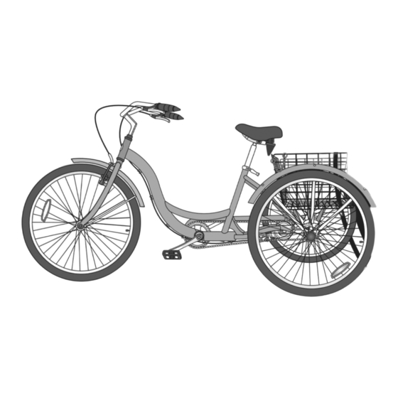
26" Adult Tricycle
Do not return to store. Call toll free (800) 626-2811 for assistance and replacement parts.
The owner's manual contains safety, assembly, use, and maintenance instructions. The 26" Adult Tricycle must be
assembled by an adult who has read and understands the instructions in this manual. Keep the packaging away from
children and dispose all packaging before use.
Advertisement
Table of Contents

Related Manuals for Schwinn 26”


Summary of Contents for Schwinn 26”
- Page 1 26” Adult Tricycle Do not return to store. Call toll free (800) 626-2811 for assistance and replacement parts. The owner’s manual contains safety, assembly, use, and maintenance instructions. The 26” Adult Tricycle must be assembled by an adult who has read and understands the instructions in this manual. Keep the packaging away from children and dispose all packaging before use.
-
Page 3: Table Of Contents
Contents 1 Introduction Rear Brake Adjustment ....25 Brake Locking Buttons ....27 Safety Signal Words . -
Page 4: Introduction
Introduction Toll free: 1-800-626-2811. This manual contains important information Customer Service hours: 8 AM- 5 PM (Central regarding safety, assembly, use, and maintenance Standard Time,CST) Monday thru Friday. of the tricycle but is not intended to be a complete or comprehensive manual covering all aspects concerning You may also reach us at: bicycle ownership. -
Page 5: Safety Signal Words
Safety Safety Signal Words User Responsibility The following safety signal words indicate a safety • All persons assembling, using, and maintaining message. The symbol alerts you to potential hazards. the tricycle must read and understand the safety Failure to follow the warning may result in damage to warnings and operating instructions in this manual property, injury, or death. -
Page 6: Protective Gear And Clothing
• Pants with loose pant legs. If necessary, always Protective Gear and Clothing tuck pant legs into a sock or use a leg band to Always wear proper attire when riding the tricycle, you avoid the clothing becoming caught in the should wear: drive chain. -
Page 7: Wet Weather
• Always ride defensively in a predictable, straight • Wear proper riding attire, reflective if possible, line. Never ride against traffic. and avoid open toe shoes. • Concentrate on the path ahead. Avoid pot holes, • Avoid wearing loose pants. If you are wearing gravel, wet road markings, oil, curbs, speed loose pants, tuck the pant leg into a sock or use bumps, drain grates and other obstacles. -
Page 8: Night Riding
• Night Riding WARNING! • • Riding at night is not recommended. Check with local law or regulations regarding the use of lights This bicycle is intended for use as a pedal power for night riding. bicycle only. It is not designed, intended or suitable for use with the installation of an internal combustion • Ensure bicycle is equipped with a full set of engine. -
Page 9: Parts
Parts Before assembly check and see that all the parts are included. If parts are missing or damaged call customer service toll free at 1-800-626-2811 . saddle front brake lever rear brake lever handlebar plastic wheel wire basket front fender caps (2) seat stem main frame... - Page 10 Hardware Handlebar Hardware Rear Wheel Axle Hardware stem wedge cap Frame Assembly Hardware 2 plastic caps 2 nuts 2 washers Basket Hardware 4 nuts 4 washers 4 square bolts Secondary Chain Hardware 4 bolts 8 washers secondary chain chain link plate master link chain pin Front Wheel Axle Hardware...
-
Page 11: Assembly
Assembly WARNING! Getting Organized The following tools and items are needed for assembly: Improperly assembly of the tricycle may result in • Phillips head screw driver (minimum four inch shaft) unexpected product performance and serious injury or death. Assemble the tricycle according to the • 6 mm, 10 mm Allen keys instructions in this manual or have a professional • Adjustable wrench or 10 mm, 15 mm, and 17 mm... -
Page 12: Initial Set-Up - Attach The Handlebars
Initial Set-up - Attach the Handlebars Parts: Handlebar, main frame 4 . Rotate the handle bar so it is square with the fork. Hardware: The stem wedge bolt and binder bolt come 5 . Tighten the stem wedge bolt to lock the stem attached to the handlebar. - Page 13 binder bolt Stem Minimum insertion mark stem wedge bolt main frame...
-
Page 14: Attach The Rear Frame
Attach the Rear Frame The flat side of the Parts: rear frame, main frame Hardware: 4 nuts, 4 square bolts, 4 washers, come square bolt should be facing up. attached to the frame. Remove this hardware before you begin this procedure . Tools: None required. 1 . -
Page 15: Attach The Secondary Chain
Attach the Secondary Chain Parts: secondary chain, frame assembly Important! Check the rear frame is square Hardware: master link, chain link plate, chain pin (perpendicular) to main frame. Failure to square Tools: Needle Nose Pliers, 17 mm open and box the frames will affect performance of the tricycle. -
Page 16: Attach The Rear Wheels
Attach the Rear Wheels WARNING! 4 . Screw the plastic caps on each end of the axles. Failure to properly tighten the nuts holding the wheels Note: The drive onto the tricycle may result in poor riding performance, wheel hub has the tire falling off and serious injury or death. -
Page 18: Attach The Front Fender
Attach the Front Fender Parts: Front fender, main frame 3 . Remove the hardware from the fork. Hardware: washer, long screw, small screw, 4 . Position the front fender so the attachment bar is contoured washer on the outside of the main frame. Tools: Phillips head screwdriver, adjustable pliers 5 . - Page 19 Note: The fender will be positioned and firmly fastened after the front tire is attached. brake noodle cable anchor bolt brake carrier hex wrench Decal should be on the outside of the frame.
-
Page 20: Attach The Front Wheel
Attach the Front Wheel WARNING! Failure to properly tighten the nuts holding the wheels onto the tricycle may result in poor riding performance, the tire falling off and serious injury or death. Be sure the wheels are securely attached to the frame before Before proceeding to the next step, using the tricycle. -
Page 21: Assemble The Front Brake
Assemble the Front Brake cable adjustment WARNING! barrel slot cable nut slot Failure to properly set the brakes may result in the inability to stop the tricycle movement and cause serious injury or death. Be sure the brakes are functioning properly before using the tricycle. - Page 22 Attach the Brake Cable to the Brake Carrier Adjust the Brake Cable 1 . Squeeze the two brake arms together until the brake Parts: Brake cable, brake arms pads touch the wheel rim. Tools: 5 mm allen wrench 2 . With your opposite hand, pull the brake cable and 1 .
- Page 23 Check for the brake pads for the following conditions: See pages 19 -22 to adjust and align the brake pads. cable anchor bolt 1/8” Clearance between the brake pad and wheel rim is a 1/8” (3 mm) gap. Brake pads are aligned (parallel) with the rim Brake pads are centered on the wheel rim.
- Page 24 Centering the Brake Pads If you squeeze the brake lever and one brake arm Using a phillips head screwdriver, adjust the brake moves more than the other, (or not at all), the brake is arm screws on either side of the brake arm. not centered. You will need to fine tune the brake pads.
- Page 25 Even space between brake pad and wheel Brake pads are centered on Wheel is centered brake arm screw each side of the wheel Note: If you run out of Even space adjustment capability on one brake arm between wheel screw side, adjust the screw on the and fork opposite side.
- Page 26 Aligning the Brake Pads Tools: 5 mm Allen wrench 2 . Using a 5 mm Allen wrench, loosen the screw holding the pad. Pad alignment should be done before centering. improper alignment can cause centering issues. For 3 . Move and rotate the pad so it is centered on the rim example the pad could be touching the tires or part of and parallel with the ground.
- Page 27 Front Brake Adjustment Checks 1 . Squeeze the brake lever as hard as you can several times to determine the cable is securely attached Squeeze the brake and the brake pads return to the center position. lever to check brake 2 .
-
Page 28: Rear Brake Adjustment
Rear Brake Adjustment 1 . Loosen pinch bolt on pad control lever with a 10 mm WARNING! open ended or adjustable wrench. 2 . Loosen the cable adjustment barrel on the brake lever Failure to properly set the brakes may result in the two turns and tighten the adjustment barrel lock nut. - Page 29 cable adjustment barrel rear brake lever adjustment brake band on drum barrel lock nut rear brake brake cable shell inner wire pinch bolt adjusting pad control brake cable seated in the lever barrel bolt adjusting barrel bolt...
-
Page 30: Brake Locking Buttons
Brake Locking Buttons Both the rear and front brake handles are equipped with brake locking buttons. The purpose of the brake locking button is to keep your tricyle from rolling when you have it parked. To lock the brakes: 1 . Squeeze the brake lever tight. 2 . -
Page 31: Attach The Rear Fenders
Attach the Rear Fenders Parts: Rear Fenders, rear frame 8 . Repeat steps one through six for the second slot. Tools: Phillips Head screwdriver (minimum 4” shaft) 9 . Firmly tighten both screws. Hardware: 4 nuts, 4 screws, 8 washers The hardware comes attached to the frame . -
Page 32: Assemble The Wire Basket
Assemble the Wire Basket 1 . Fold the basket sides up. 2 . Align the rings located on two corners of the basket. 3 . Insert the pins on the end of the chain through the rings on the corners of the basket... -
Page 33: Attach The Wire Basket
Attach the Wire Basket Parts: Wire basket, rear frame Tools: Phillips Head screwdriver Hardware: 4 screws, 8 washers The hardware comes attached to the frame . Remove the hardware before you begin this procedure . 1 . Place the wire basket on the rear frame and align the slots on the basket with the holes in the frame. -
Page 34: Attach The Saddle
Attach the Saddle WARNING! Insufficient locking pressure on the seat stem may result in the seat slipping, loss of control and serious injury or death. Be sure the seat is locked and capable of supporting the weight of the rider before using the tricycle. Minimum insertion mark Parts: Saddle, Saddle stem Tools: 14 mm open and box end wrench, Adjustable Pliers 1 . -
Page 35: Attach The Pedals
Attach the Pedals NOTICE: Attaching a pedal to the incorrect side can 5 . If the spindle is entering the hole cleanly then use a strip the pedal threads and cause irreparable damage. 15 mm wrench or pliers to tighten completely. Visually match the R and L stickers on the pedal and 6 . Repeat steps two through five for the opposite pedal. -
Page 36: Adjust The Handlebar
Adjust the Handlebar 4 . Rotate the handle bar so it is square with the fork. WARNING! 5 . Tighten the stem wedge bolt to lock the stem in place. Failure to firmly tighten the handlebar stem wedge 6 . Loosen the handlebar binder bolt and rotate the bolt, handlebar binder bolt, seat stem, and bar end handlebar until the rider feels they have control of extension clamping bolts may cause a sudden shift... -
Page 37: Adjust The Seat
Adjust the Seat WARNING! Failure to insert the handlebar and seat stems beyond the “Minimum Insertion” line may cause the stem to break resulting in damage to the stem, loss of control, falling, serious injury or death. Insert the handlebar and seat stem into the frame until the Minimum Insertion Mark is not visible. -
Page 38: Use
WARNING! The brake control cables are lubricated, correctly adjusted and display no obvious wear. Failure to follow all local and state regulations and laws The brake control levers are lubricated and pertaining to bicycle use as well as the safety warnings tightly secured to the handlebar. - Page 39 binder bolt Wheels and Tires handlebar The rims do not have dirt or grease on them. The wheels are properly attached to the stem tricycle and the axle nuts are tight. The wheel spokes are not loose or broken. ...
- Page 40 Chains Accessories The reflectors are good shape, properly placed The chains are oiled, clean and run smoothly and not obscured. Note: Extra maintenance is required in wet or dusty conditions. All other fittings on the bike are properly and securely fastened, and functioning. Bearings The rider is wearing a properly fitted helmet (protective gear if necessary) and that clothing All bearings are lubricated, run freely and ...
-
Page 41: Maintenance And Troubleshooting
Maintenance and Troubleshooting This section presents important information on WARNING! maintenance and will assist you in determining the proper course of action to take if you do have a Failure to conduct maintenance on the tricycle may problem with the operation of the tricycle. result in malfunction of a critical part and serious If you have questions regarding maintenance please injury or death. - Page 42 Lubrication Schedule Component Lubricant Method Weekly Chains Chain lube or light oil Brush on or squirt Brake calipers Three drops from oil can Brake levers Two drops from oil can Every Six Months Freewheel Two drops from oil can Brake cables Lithium based grease Remove cable from casing.
-
Page 43: Parts Maintenance
Parts Maintenance Wheels Frequency: Inspect and maintain before each use Inspect Action Maintenance Rims Inspect for dirt and grease Use a clean rag or wash with soapy water, rinse, and air dry. Wheels Check the wheels are securely fastened to Adjust if necessary and tighten axle nuts. - Page 44 Tires Frequency: Inspect and maintain before each use Inspect Action Maintenance Tire Inflation Check tire pressure Inflate tire to the pressure indicated on the tire sidewall. See “Inflating a Tire Tube” for more detail. If the tire is flat see “Fixing a Flat Tire” for more detail. Check the bead is properly seated while Reduce air pressure in the tube and re-seat inflating or refitting the tire. the bead. Spin wheel and check rotation / alignment Loosen axle nut(s) and adjust until properly is smooth and even.
- Page 45 Brakes Frequency: Inspect and maintain before each use Inspect Action Maintenance Levers Check the levers are securely Position the levers to fit the rider’s fastened to the handlebar. grip and screw tight to handlebar. Pads Check pad position, gap and See all sections under “Assemble pressure. the Front Brake”.
- Page 46 Drivetrain (pedals, chains, chainwheel, crank set, freewheel) Frequency: as noted Inspect Action Maintenance Pedals Every month, check each pedal is securely If necessary, re-set and tighten. set and tighten into the crank arm. Before each ride, check each front and rear Clean or replace. pedal reflectors are clean and in place. Pedal Bearings Every month, check the pedal bearings See bicycle mechanic for repair.
-
Page 47: Hub Bearings
Drivetrain maintenance continued . . . Inspect Action Maintenance Crank Set Every month, check the crank set (crank Replace cable. arms, chain rings, and bottom bracket axle and bearings) is correctly adjusted and tight. Remove the primary chain Hub Bearings Hub bearings require special thin wrenches called 4 . -
Page 48: Inflating The Tire Tube
Inflating the Tire Tube 5 . Complete inflation. WARNING! 6 . Be sure the tire is evenly seated on the rim, both sides. If not release some air and repeat steps three An unseated tire can rupture unexpectedly and cause through six. serious injury or death. -
Page 49: Repairing A Flat Tire
Repairing a Flat Tire 7 . Inflate the tube ¼ full and place inside tire. WARNING! 8 . Insert the valve stem through valve stem hole in rim. An unseated tire can rupture unexpectedly and cause 9 . Start at the valve stem and install the first bead onto serious injury or death. Be sure the tire is properly the rim. -
Page 50: Warranty
Warranty Frame must be returned for inspection at customer’s LIMITED WARRANTY AND POLICY expense. Please note: the fork is not part of the frame. A ON REPLACEMENT PROCEDURES & lifetime warranty on your frame does not guarantee that RESPONSIBILITIES the product will last forever. The length of the useful life cycle will vary depending on the type of bike, riding Your purchase includes the following warranty which conditions and care the bicycle receives. - Page 51 initial consumer purchaser, subject to the Terms and CONDITIONS OF WARRANTY Conditions of the warranty listed below. If failure of any 1 . Your bicycle has been designed for general part should occur due to faulty materials or workmanship transportation and recreational use, but has not been during the warranty period, the part will be replaced.
-
Page 52: Purchase Record
Purchase Record Fill out this record and retain it as well as your sales receipt a record of your purchase and potential warranty claims. Name: Address: State/City/Zip: Date of Purchase: Place of Purchase: Serial Number: Model Number: Date Code:... - Page 54 Pacific Cycle 4902 Hammersley Road Madison, WI 53711 Service: 800-626-2811 www.schwinn.com...
Need help?
Do you have a question about the 26” and is the answer not in the manual?
Questions and answers