Table of Contents
Advertisement
Technical Procedure
Enhanced Images: Pictures can be zoomed in to any level for
detail. Use the standard zoom tools for your platform to zoom in.
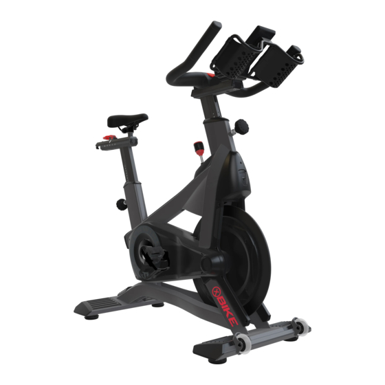
This document covers procedures for the Schwinn Z and X bikes. The Schwinn Z is pictured, procedures are
applicable for the Schwinn X cycle except where specified. Click on procedure below to jump to section:
Schwinn X/Z Troubleshooting & Replacement
Applies to: Schwinn X (9-7470 + 9-7480), Schwinn Z (9-7510 + 9-7520)
Fore-Aft Adjustment Lever Replacement ...................................................... 2
Tighten Loose Handlebars or Seat................................................................. 7
Cycle Belt and Flywheel Replacement ......................................................... 10
Z Bike Gear-Angle Sensor Replacement ..................................................... 16
Z Bike LED Board Replacement ................................................................. 19
Crank Removal............................ ................................................................. 24
Pedal Removal............................ ................................................................. 25
................................................................. 22
................................................................. 26
7
8
22
23
Page 1
637-8808 Rev. J
Advertisement
Table of Contents

Related Manuals for Schwinn Z


Summary of Contents for Schwinn Z
-
Page 1: Table Of Contents
Use the standard zoom tools for your platform to zoom in. This document covers procedures for the Schwinn Z and X bikes. The Schwinn Z is pictured, procedures are applicable for the Schwinn X cycle except where specified. Click on procedure below to jump to section: Fore-Aft Adjustment Lever Replacement ............ -
Page 2: Fore-Aft Adjustment Lever Replacement
• For handlebars: 727-0176-XX “ASSY, CAM LEVER, HBAR” Please note that 300-0245 300-0245 “BLOCK, GAUGE, TORQUE, SEAT, UGC” is only required for bikes PRIOR to serial number(s): GC7470L22091069 (Schwinn XA), GC7520L21491157 (Schwinn ZA), GC7510L2213127 (Schwinn ZS), GC7480L22141001 (Schwinn XS). Seat Slider... - Page 3 Notice: Step 5 is ONLY valid for bikes PRIOR to serial number GC7470L22091069 (Schwinn XA), GC7520L21491157 (Schwinn ZA), GC7510L2213127 (Schwinn ZS), GC7480L22141001 (Schwinn XS). Fig. 4 Page 3 637-8808 Rev.
- Page 4 Technical Procedure Ensure that the fore/aft adjustment lever is closed, then use a torque wrench with a 11mm deep socket to tighten the fore/aft lever adjustment nut to 4 Nm (2.95 Ft-Lbs). Reinstall the seat slider and locking screw from Steps 1+2. This will conclude the procedure - DO NOT CONTINUE TO STEP 7.
- Page 5 Technical Procedure Handlebar Slider Flip the fore/aft adjustment lever up. Fig. 6 Move the handlebars forward until the fore/ aft adjustment lever nut is visible through the hole on the underside of the handlebar post. Fig. 7 Use a ratchet wrench with a 11mm deep socket to remove the 1/4”...
- Page 6 Technical Procedure NOTE: If a torque wrench is not available, please skip to Step 4. Close the fore/aft adjustment lever, then use a torque wrench with a 11mm deep socket to tighten the fore/aft lever adjustment nut to 3 Nm (2.21 Ft-Lbs). This will conclude the procedure.
-
Page 7: Tighten Loose Handlebars Or Seat
• #2 Phillips Screwdriver • Torque Wrench • 10mm Deep Socket • 3mm Allen Key NOTE: While the images below show a Schwinn Z cycle, this procedure is also applicable for the Schwinn X cycle. Handlebars Flip the fore/aft adjustment lever up. -
Page 8: Seat
Notice: Step 3 is ONLY valid for bikes PRIOR to serial number GC7470L22091069 (Schwinn XA), GC7520L21491157 (Schwinn ZA), GC7510L2213127 (Schwinn ZS), GC7480L22141001 (Schwinn XS). Fig. 14 Page 8 637-8808 Rev. - Page 9 Technical Procedure Ensure that the fore/aft adjustment lever is closed, then use a torque wrench with a 10mm deep socket to tighten the fore/aft lever adjustment nut to 4 Nm (2.95 Ft-Lbs). Reinstall the seat slider and locking screw from Steps 1+2. This will conclude the procedure - DO NOT CONTINUE TO STEP 7.
-
Page 10: Cycle Belt And Flywheel Replacement
Technical Procedure Cycle Belt and Flywheel Replacement Required Tools: • 3mm Allen Key • 4mm Allen Key • 6mm Allen Key • #2 Phillips Head Screwdriver • 18mm Open-Ended Wrench • 19mm Open-Ended Wrench x2 • Permanent Marker or Pencil WARNING: Procedure below involves removal of the flywheel. - Page 11 Technical Procedure Use a 4mm allen key to remove the two (2) socket head cap screws securing the rear of the right side belt guard to the bike, use a 3mm allen key to remove the two (2) button head cap screws from the front of the right side seld belt guard, then remove the belt guard.
- Page 12 Technical Procedure Use a #2 phillips screwdriver to remove the four (4) button head screws securing the inner right fork guard assembly to the bike, then remove the inner fork guard. Fig. 21 Use a 3mm allen key to remove the five (5) button head cap screws from the left side outer fork guard, then remove the fork guard.
- Page 13 Technical Procedure Use a 3mm allen key to remove the button head cap screw from the top of the outer generator belt guard, use a #2 phillips screwdriver to remove the pan head machine screw from the bottom of the belt guard, then remove the belt guard.
- Page 14 Technical Procedure Use a 6mm allen key to loosen the belt tension screw to loosen the belt. NOTE: Be sure to mark the location of the belt pulley tension block before loosening, so during reinstall, the belt tension can be returned to factory settings.
- Page 15 After removing the flywheel from the forks, the flywheel, drive belt, and/or generator belt can all be replaced. Note For Z Bike: If replacing the flywheel, remember to remove the generator belt from the left side of the flywheel and install it onto the new flywheel.
-
Page 16: Z Bike Gear-Angle Sensor Replacement
Use a 4mm allen key to remove the socket head cap screw securing the nose cover to the bike, then remove the cover. Fig. 31 Disconnect the gear sensor from the junction board. Fig. 32 Applies to: Schwinn Z Bike (9-7510 + 9-7520) Page 16 637-8808 Rev. J... - Page 17 Technical Procedure Use a #2 phillips screwdriver to remove the pan head screw securing the sensor to the brake assembly. Fig. 33 Remove the sensor from the brake assembly. Follow steps 1-4 in reverse to install the new sensor. Fig. 34 Page 17 637-8808 Rev.
- Page 18 Technical Procedure Tap the buttons simultaneously then tap the button to enter Maintenance Mode. Press the button until GEAR is shown in the message center then press the button. If the value in the message center reads OFF Press the button to switch to ON then press the button to save the change.
-
Page 19: Z Bike Led Board Replacement
LED board. Skip to Step 6. Notice: While the instructions below show the right side LED board replacement, they are still valid for the left side LED board replacement. Fig. 37 Applies to: Schwinn Z Bike (9-7510 + 9-7520) Page 19 637-8808 Rev. J... - Page 20 Technical Procedure Use a 4mm allen key to remove the two (2) socket head cap screws from the front of the left side belt guard. Fig. 38 Use a 3mm allen key to remove the two (2) button head cap screws from the front of the right side belt guard, then remove the four (4) button head cap screws securing the right side, outer fork guard from the frame.
- Page 21 Technical Procedure Carefully disconnect the LED cable from the LED board then remove the LED board. Fig. 41 When reconnecting the LED cable to the LED board, be sure that the LED cable passes through the extruded boss of the inner fork shroud - this applies to both the left and right side.
-
Page 22: Z Bike Battery Replacement
Fig. 43 Disconnect the battery from the battery service cable. Remove the battery from the battery retention clip and replace. Fig. 44 Applies to: Schwinn Z Bike (9-7510 + 9-7520) Page 22 637-8808 Rev. J... -
Page 23: 4Iiii Crank Arm Battery Replacement
Technical Procedure 4iiii Crank Arm Battery Replacement Use a small phillips screwdriver to remove the screw securing the battery cover to the crank arm, remove the battery cover, remove the old batteries, then install the new AA batteries. Fig. 45 Page 23 637-8808 Rev. -
Page 24: Crank Removal
Technical Procedure X+Z Bike Crank Arm Removal Required Tools: • 8mm Allen Key • Crank Puller Tool with 22mm X 1mm Threading (CWP-7) Use an 8mm allen key to remove the crank bolt securing the crank arm to the bottom bracket. -
Page 25: Pedal Removal
Technical Procedure X+Z Bike Pedal Removal Required Tools: • 8mm Allen Key • Crank Puller Tool with 22mm X 1mm Threading (CWP-7) Use an 8mm allen key to remove the pedal bolt securing the pedal to the crank arm. Fig. 48 Use a crank puller tool to remove the pedal. -
Page 26: Flywheel Position Adjustment
Technical Procedure Flywheel Position Adjustment Required Tools: • 3mm Allen Key • 4mm Allen Key • 19mm Open-Ended Wrench In cases where the flywheel is not centered between the brake magnets resulting in rubbing or noise, it will be necessary to adjust the flywheel position. Use a 4mm allen key to remove he two (2) socket head cap screws securing the left side belt guard cap. - Page 27 Technical Procedure Use a 4mm allen key to remove the two (2) socket head cap screws securing the rear of the right side belt guard to the bike, use a 3mm allen key to remove the two (2) button head cap screws from the front of the right side seld belt guard, then remove the belt guard.
- Page 28 Technical Procedure Use a 3mm allen key to remove the five (5) button head cap screws from the left side outer fork guard, then remove the fork guard. Carefully disconnect the LED board cable from the LED board. Fig. 55 Use a 19mm open-ended wrench to loosen the flywheel axle nut.
- Page 29 Technical Procedure Adjust the flywheel position using a 5mm allen key to turn the left and right flywheel jack screws in 1/4 turn increments until the flywheel is centered between the brake magnets. Fig. 57 Fig. 58 Brake Magnets Once the flywheel is centered between the brake magnets, be sure to tighten the flywheel axle before reinstalling the shrouds.
Need help?
Do you have a question about the Z and is the answer not in the manual?
Questions and answers