Table of Contents
Advertisement
Quick Links
Advertisement
Table of Contents

Related Manuals for GE ProBridge Ethernet PBe


Summary of Contents for GE ProBridge Ethernet PBe
-
Page 1: User Manual
ProBridge Ethernet User Manual... - Page 2 Any similarity to names and addresses of actual businesses or persons is entirely coincidental. Trademarks GE and the GE monogram are registered trademarks of General Electric. and patents PBe product and logo are trademarks of GE Security. Other trade names used in this document may be trademarks or registered trademarks of the manufacturers or vendors of the respective products.
-
Page 3: Table Of Contents
Required information ......... . 9 Required DIP switch information ....... 10 Installation steps. - Page 4 ProBridge Ethernet User Manual...
-
Page 5: Introduction
Introduction This is the GE ProBridge Ethernet User Manual for model PBe. This document includes detailed instructions explaining: • how to setup and install the PBe ProBridge and • how to connect to single or multiple ATM sites. There is also information describing how to contact technical support if you have questions. -
Page 6: Conventions Used In This Document
ProBridge Ethernet User Manual Conventions used in this document The following conventions are used in this document: Bold Italic Blue italic Monospace Safety terms and symbols These terms may appear in this manual: CAUTION: WARNING: Menu items and buttons. Emphasis of an instruction or point; special terms. File names, path names, windows, panes, tabs, fields, variables, and other GUI elements. -
Page 7: Overview
DVR and permits associating transaction data with specific cameras. GE assumes no responsibility for the amount and type of information available, the operation, non-operation, or erroneous operation of these third-party transaction products. -
Page 8: Product Contents
ProBridge Ethernet User Manual Product contents The PBe system consists of the ProBridge unit, this manual, an Ethernet cable, a PBe to DVR cable, a PBe to PC cable, and a power supply, as shown in Figure 1. Figure 1. Product contents 4310-0040 Ethernet cable 0150-0315... -
Page 9: Installation Environment
Installation environment Power. Ensure that the installation site’s AC power is stable and within the rated voltage of the external power supply. If the site’s AC power is likely to have spikes or DIPs, use power line conditioning or an uninterruptible power supply. - Page 10 ProBridge Ethernet User Manual 4310-0007 120 VAC power supply Power supply input • Voltage: 120 VAC • Tolerance: • Frequency: 60 Hz Power supply output • Voltage: 12 VDC • Current: 110 mA • Power: 1.3 watts • Connector: 2.1 mm female barrel. Center positive. 4310-0008 220VAC power supply Power supply input •...
-
Page 11: Installation
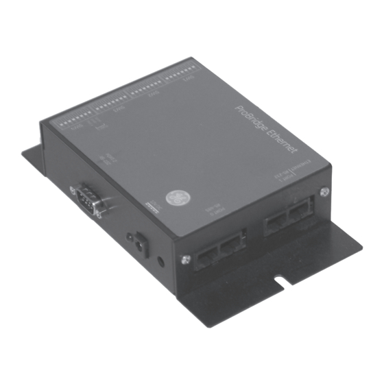
Installation Before installation, please familiarize yourself with the PBe and its typical system layout. PBe components Figure 2. PBe landmarks Port 0/RS-485 Connects multiple PBes together Power connection Port 2/RS-232 Connects to the PC Ethernet Port Port 1/RS-232... -
Page 12: Typical System Layout
ProBridge Ethernet User Manual Typical system layout The following figure shows a typical multiple ATM layout. Figure 3. Multiple ATM system layout RS232 port 4310-0034B RJ45 to RJ45 cable Ethernet Existing ATMs 4310-0040 Ethernet cable... -
Page 13: Installation Overview
The basic steps required to install the PBe are: 1. Physically connect the PBe interface to the network switch or hub and the DVR using the supplied cables. 2. Program monitor mode to on by setting SW1 switches 1 to 4. See SW1 switches 1 to 4 settings. -
Page 14: Required Dip Switch Information
ProBridge Ethernet User Manual Required DIP switch information Important switch assignments Table 1. Important switch assignments Default switch settings Table 2. Default switch settings Installation steps 1. Select the camera number (1-16) on the DVR on which to associate the ATM transaction text. This is done by... - Page 15 5-8 on SW1. See page 21. 2. Connect the PBe to the network switch or hub using the supplied 4310-0040 Ethernet cable. 3. Connect the PBe to the DVR using the supplied 4310- 0034 cable. Plug one end into port 1 of the PBe and the other end into the RS-232/2 port of the DVR.
-
Page 16: Programming
ProBridge Ethernet User Manual Programming After you install the PBe, you need to program the ProBridge for operation. This is accomplished by using HyperTerminal or manually setting the DIP switches. HyperTerminal configuration You will need the following equipment to program the PBe using HyperTerminal: •... - Page 17 Figure 4. Laptop connected to PBe 4. The Connection Description dialog box will display. Type in a name for this session (PBe) and click OK. 5. The Connect To dialog box display. Select the COM port you are connected to in the Connect Using drop-down list.
- Page 18 ProBridge Ethernet User Manual Figure 5. HyperTerminal programming mode 2. Press the Enter key twice to bring up the Main Menu. Figure 6. Main menu...
-
Page 19: Main Menu
Main Menu There are five menu selections on the Main Menu: • Exit - Exits the maim menu and saves any changes. • PBe Set-up - provides IP address setup and Ethernet device selection. • Terminal IP/Camera Set-up - Enables or disables the IP camera and provides addressing options. - Page 20 • Verifone POS • Ethernet data analyzer Note: The Ethernet device can also be selected by DIP switch. See switches 1 to 8 Terminal IP/Camera Set-up menu Selecting option #3 from the main menu launches the Terminal IP/Camera Set-up menu.
- Page 21 4. The camera/terminal will redisplay with the new information. 5. Pressing the enter key will terminate the camera/terminal IP set-up and return you to the previous menu. Figure 9. The camera/terminal IP table Option #3 lets you enable/disable the Use IP for Camera command.
-
Page 22: Manual Dip Switch Configuration
1. Remove the RS-232 cable and reconnect the PBe to the DVR. Manual DIP switch configuration The Ethernet Device and Camera Selection can also be selected manually by changing the DIP switch setting see settings on page 20. Follow the steps below to change the DIP switches: 1. - Page 23 3. Set the DIP switches per the tables in DIP switch settings on page 20 to match the changes desired. 4. Reconnect the PBe to the DVR. 5. Reapply power to the PBe.
-
Page 24: Sw1 Switche 1 To
ProBridge Ethernet User Manual DIP switch settings This chapter deals in detail with the DIP switch settings. The PBe must be re initialized before any changes to the switch settings will be recognized. SW1 switches 1 to 4 Switches 1 to 4 on SW1 are for turning monitor mode on or off. -
Page 25: Sw1 Switche 5 To
SW1 switches 5 to 8 Switches 5 to 8 on SW1 are for associating a specific camera on the DVR to the PBe. Table 4. SW1 switches 5 to 8 - Camera number selection Camera number... -
Page 26: Sw3 Switche 1 To
ProBridge Ethernet User Manual SW3 switches 1 to 8 The switch positions on SW3 are for selecting the Ethernet device type. Table 5. SW3 switches 1 to 8 - Device type Switch function Ethernet Analyzer Generic Native ATM Verifone POS These switches are reserved for technical support. -
Page 27: Accessing The Webserver
Accessing the Webserver The PBe has a built-in webpage for simple configuration changes and remote upgrade. To access the webpage do the following: 1. Obtain the IP addresses for the PBe. The default address are: • IP Address: 3.112.55.79 • Subnet mask: 255.255.254.0 •... - Page 28 ProBridge Ethernet User Manual Figure 10. The PBe home page Click on any of the hyperlinked text to navigate to that feature’s page.
-
Page 29: Troubleshooting
Use the table below to solve some of the most common problems Table 7. Troubleshooting table Problem No red LEd No text on DVR text Not capturing data from switch Probable cause Fuse is bad No Power DVR baud rate incorrect Cable not connected... -
Page 30: Technical Specifications
ProBridge Ethernet User Manual Technical specifications General Housing: Dimensions: Weight: Color: Environmental Operating temperature: Relative humidity: Electrical AC power: Voltage range: Current: DC power: Power supply voltage: Current: Power consumption: Metal enclosure 4 x 7 x 1.5 in. (100 x 175 x 38 mm) 5.2 oz. -
Page 31: Cable Specifications
Cable Specifications PBe to DVR Part number: Communication type: Connector type: Length: Figure 11. 4310-0034B cable Pin 1 4310-0034B RS-232 RJ45 5 ft. (1.52 m) Pin 1... - Page 32 ProBridge Ethernet User Manual PBe to PC Part number: Communication type: Connector type: Length: Figure 12. 4310-0061 cable 4310-00061 RS-232/Null Modem DB9-F, DB9-F 6 ft. (1.82 m)
- Page 33 PBe Ethernet cable Part number: Communication type: Connector type: length: Figure 13. 4310-0040 PBe Ethernet 4310-0040 Ethernet RJ45, RJ45 6 ft. (1.83 m)
-
Page 34: Contacting Technical Support
Be ready at the equipment before calling for technical support. Online publication library Another great resource for assistance with your GE product is our online publication library, available to all of our customers. To access the library, go to our website at the following location: http://www.gesecurity.com...
Need help?
Do you have a question about the ProBridge Ethernet PBe and is the answer not in the manual?
Questions and answers