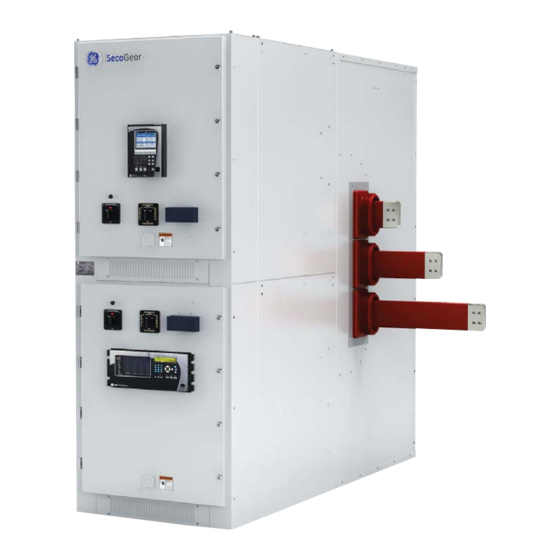
GE SecoGear Application Manual
5kv - 15kv ieee metal-clad switchgear
Hide thumbs
Also See for SecoGear:
- Installation, operation and maintenance manual (56 pages) ,
- User manual (36 pages)

Related Manuals for GE SecoGear


Summary of Contents for GE SecoGear
- Page 1 GE Energy Connections Industrial Solutions DET-882 Application and Technical Guide SecoGear Switchgear...
- Page 2 Features may be described herein that are not present in all hardware and software systems. Indicates a hazardous situation that, if not avoided, could GE Industrial Solutions assumes no obligation of notice to result in death or serious injury. holders of this document with respect to changes subsequently made.
-
Page 3: Table Of Contents
SecoGear Medium-voltage Switchgear Application and Technical Guide DET-882 TABLE OF CONTENTS SECTION 1. SecoGear Switchgear Concepts and Basic Configurations ..................1 SecoGear Metal-clad Switchgear ....................................... 1 Switchgear Standards ............................................3 Underwriters Laboratories, Inc. (UL) ....................................3 Service Conditions ............................................3 Temperature .............................................. - Page 4 DET-882 SecoGear Medium-voltage Switchgear Application and Technical Guide Battery Capacity and Sizing ......................................... 21 Battery Chargers ............................................22 AC Control Power Equipment ........................................23 Application ..............................................23 Selection ................................................23 Guide to Estimating Heat Loss........................................24 SECTION 4. System and Equipment Protection ..........................25 Basic System Protection ..........................................
- Page 5 Location of Optional Devices ......................................50 Standard Breaker and Auxiliary Configurations ................................52 Standard Tie Breaker and Auxiliary Configurations ..............................53 SECTION 6. Standard SecoGear Construction, Features, and Installation ................55 Documentation ..............................................55 Construction ............................................... 55 Indoor Equipment ............................................55 Hardware................................................
- Page 6 DET-882 SecoGear Medium-voltage Switchgear Application and Technical Guide Wiring................................................60 Power Termination Compartment ..................................... 60 Ground Bus ..............................................61 Equipment Heaters ............................................ 61 Finish and Paint ............................................61 Unit Nameplates ............................................61 Accessories ..............................................61 Breaker Test Box ............................................. 61 Breaker Racking Mechanism ......................................
- Page 7 Figure 6-16: Open/Close Pushbutton Open .................................... 59 Figure 6-17: CT Mounting in Breaker Compartment ................................59 Figure 6-18: Typical Ring-Type CTs Mounted in SecoGear Breaker Cell........................60 Figure 6-19: Typical Indoor Voltage Transformer ................................60 Figure 6-20: Rear View of Two high Compartment Showing Cable Trough ......................60 Figure 6-21: Cable Trough Opening......................................
- Page 8 Table 2-1: SecoVac VB2+ Vacuum Circuit Breaker Characteristics ..........................11 Table 2-2: SecoVac Breaker Capacitor Switching Capabilities ............................12 Table 2-3: Altitude Correction Factors* for SecoVac VB2+ Circuit Breakers and SecoGear Switchgear ..........13 Table 3-1: SecoVac VB2+ IEEE Circuit Breaker Control Voltages and Currents ....................18 Table 3-2: Contact Ratings for MOC, TOC, and Breaker Auxiliary Switches ......................
-
Page 9: Section 1. Secogear Switchgear Concepts And Basic Configurations
A brief introduction to SecoGear will serve as a useful starting point to begin the application procedure. SECOGEAR METAL-CLAD SWITCHGEAR... -
Page 10: Figure 1-2: Section Contents
A brief illustration of SecoGear switchgear design concepts is provided to assist in • SecoGear allows for intermixing auxiliary and a breaker compartment in the same vertical section understanding. Certain elements in the switchgear application procedure are affected by these fundamental design features. -
Page 11: Switchgear Standards
Figure 1-9 and Figure 1-10. Additional illustrations will be provided to Not all medium-voltage switchgear assemblies assist in the layout of a SecoGear lineup in SECTION 5 qualify for UL listing. “SecoGear Switchgear Applications.”... -
Page 12: Figure 1-5: Dual Vt Rollouts, Line/Bus Connected - Upper Or Lower Section
SecoGear Medium-voltage Switchgear Application and Technical Guide DET-882 SecoGear Switchgear Concepts and Basic Configurations Figure 1-5: Dual VT Rollouts, Line/Bus Connected – Figure 1-7: 1200 A/2000 A – Upper or Lower Upper or Lower Section Breaker Section Space for 4 CTs per phase: •... -
Page 13: Rollout Configurations
DET-882 SecoGear Medium-voltage Switchgear Application and Technical Guide SecoGear Switchgear Concepts and Basic Configurations Rollout Configurations Figure 1-10: Single Rollouts Figure 1-9: Dual Rollouts Compartment A Upper Rollout Compartment A Lower Rollout Compartment B Upper Rollout Compartment B Fuse Rollout... -
Page 14: Two-High Breaker And Auxiliary Stacking
SecoGear Medium-voltage Switchgear Application and Technical Guide DET-882 SecoGear Switchgear Concepts and Basic Configurations Two-High Breaker and Auxiliary Stacking Figure 1-13: Breaker in Compartment A, Bus-connected VTs and CPT Fuse Rollout in Compartment B SecoGear allows stacking of various modules or compartments into a vertical section. -
Page 15: Figure 1-15: Breaker In Compartment A, Line- And Bus-Connected Vt Rollouts In Compartment B
DET-882 SecoGear Medium-voltage Switchgear Application and Technical Guide SecoGear Switchgear Concepts and Basic Configurations Figure 1-15: Breaker in Compartment A, Line- and Bus- Figure 1-17: Breaker in Compartment B, Bus-connected connected VT Rollouts in Compartment B CPT in Compartment A... -
Page 16: Figure 1-19: Breaker In Compartment B, Bus-Connected Vts And Cpt In Compartment A
SecoGear Medium-voltage Switchgear Application and Technical Guide DET-882 SecoGear Switchgear Concepts and Basic Configurations Figure 1-19: Breaker in Compartment B, Bus-connected Figure 1-21: Typical Two-high Breaker Section – VTs and CPT in Compartment A Cabling Below GSCT Breaker GSCT Breaker... -
Page 17: Figure 1-23: Breaker In Compartment A - Cabling Above, Bus Entry In Compartment B - Cabling Below
DET-882 SecoGear Medium-voltage Switchgear Application and Technical Guide SecoGear Switchgear Concepts and Basic Configurations Figure 1-23: Breaker in Compartment A – Cabling Above, Figure 1-25: Bus-connected VTs in Compartment A, Bus Bus Entry in Compartment B – Cabling Below Tie Breaker in Compartment B... -
Page 18: Section 2. Circuit Breaker Selection
2,400 V through 15,000 V. System Frequency SecoGear Metal-clad switchgear is rated to 60 Hz as a standard with the option to provide a 50 Hz solution as required. When determining the system frequency of any switchgear, remember that the frequency rating should be the same as the nominal frequency of the power system. -
Page 19: Closing And Latching Current
DET-882 SecoGear Medium-voltage Switchgear Application and Technical Guide Circuit Breaker Selection Table 2-1: SecoVac VB2+ Vacuum Circuit Breaker Characteristics Characteristic 1200/31.5 Rating 1200/40 Rating 2000/40 Rating Rated current 1200 A 1200 A 2000 A 4.76 kV, 8.25 kV, 4.76 kV, 8.25 kV, 4.76 kV, 8.25 kV,... -
Page 20: Capacitor Switching
(-30 °C relays, such as GE Multilin SR850. In addition to a protective [-22 °F] to 40 °C [104 °F], consult ANSI C37.20.2 for derating relay required for each of the three circuit breakers (both values applicable. -
Page 21: Breaker Accessories
0.95 higher temperature rise and lower dielectric withstand 1500 m [6000 ft] 0.987 0.92 capability. If we intend to use a SecoGear switchgear at 2100 m [7000 ft] 0.985 0.89 high altitudes we need to use the correction factors (listed 1500 m [8000 ft] 0.970... -
Page 22: Related Circuit Breaker References
SecoGear Medium-voltage Switchgear Application and Technical Guide DET-882 Circuit Breaker Selection Figure 2-2: Lift Truck Any housekeeping pad placed under the switchgear, must be less than 4 in. tall for proper operation of the lift truck. For maximum safety and ease of use, the lift truck will be locked to the switchgear when a device is being handled, either inserted or removed. -
Page 23: Figure 2-3: Secovac Vb2+ Breaker Front Panel
DET-882 SecoGear Medium-voltage Switchgear Application and Technical Guide Circuit Breaker Selection Figure 2-3: SecoVac VB2+ Breaker Front Panel Secondary disconnect plug connector Spring discharge Charging handle instructions Open pushbutton Close pushbutton Vacuum bottle label Operation counter Spring charge Open/close status indicator... -
Page 24: Typical Breaker Device Internals
SecoGear Medium-voltage Switchgear Application and Technical Guide DET-882 Circuit Breaker Selection TYPICAL BREAKER DEVICE INTERNALS Figure 2-5: System Wiring Diagram Key Note S1~S3: Energy storing travel switch Limit switch for trip free TC2: Auxiliary Contact Number. 2nd Trip coil (optional) -
Page 25: Figure 2-8: Example - Main Breaker Control Circuit, 850 Relay, Expanded Moc Switch
DET-882 SecoGear Medium-voltage Switchgear Application and Technical Guide Circuit Breaker Selection Figure 2-8: Example – Main Breaker Control Circuit, 850 Relay, Expanded MOC Switch ©2017 General Electric All Rights Reserved... -
Page 26: Section 3. Control Power Equipment
CONTROL POWER REQUIREMENTS breakers, maintenance, etc., and the end cost. Control power for SecoGear needs to have enough Breaker Close and Trip Considerations capacity to provide the maximum power required at any operating condition. It is important to have adequate... -
Page 27: Dc Battery Trip
For indoor applications where a battery bank can be located close to When initially installing SecoGear, to energize the control the switchgear, a 48 V battery operating level is suitable. power equipment first establish the control power and For more general use, a 125 V battery system is then rack in SecoVac circuit breakers one at a time. -
Page 28: Indicating Lamps
(Table 3-4) Table 3-1. Usually, only one breaker will be closed at a time, but the possibility of simultaneous closing of two or Table 3-4: GE Type HEA Lockout Relay Coil Current more breakers must be examined. This possibility will Characteristics... -
Page 29: Control Power Source Selection
DC Control Power Equipment Life expectancy Lower Higher GE does not design, manufacture, or test storage batteries. Battery Capacity and Sizing GE Switchgear Operations, when required, will select and furnish batteries and their charger as specified by the The capacity of a storage battery is usually expressed in... -
Page 30: Battery Chargers
SecoGear Medium-voltage Switchgear Application and Technical Guide DET-882 Control Power Equipment Generally, the effect of high temperatures for every 15 °F Table 3-8: Battery Sizing, Example B above 77 °F the lead-acid battery loses 50% of its useful Lead-acid Nickel-cadmium life. -
Page 31: Ac Control Power Equipment
DET-882 SecoGear Medium-voltage Switchgear Application and Technical Guide Control Power Equipment The charger must be selected with an ampere rating AC CONTROL POWER EQUIPMENT sufficient to satisfy the simultaneous demand of the Control power equipment for SecoGear Switchgear, following three functions: operated through an AC source should be powered from a ·... -
Page 32: Guide To Estimating Heat Loss
SecoGear Medium-voltage Switchgear Application and Technical Guide DET-882 Control Power Equipment GUIDE TO ESTIMATING HEAT LOSS When operating at nameplate rating, SecoGear Metal-clad switchgear heat losses per section should be estimated by adding the individual components of heat loss as shown in Table 3-10 and then add each item from Table 3-11 as they apply in the switchgear line-up. -
Page 33: Section 4. System And Equipment Protection
GE Multilin Relay product reference guide can be found at www.GEMultilin.com or directly at www.gegridsolutions.com/multilin/selector/... -
Page 34: Figure 4-1: Multilin Website Features - Motor Protection Selection
SecoGear Medium-voltage Switchgear Application and Technical Guide DET-882 System and Equipment Protection The GE Multilin website provides an easy reference to various relays and metering options available to you for use in your SecoGear equipment. Figure 4-1: Multilin Website Features – Motor Protection Selection... -
Page 35: Figure 4-2: Multilin Website Features - Digital Metering Selection
DET-882 SecoGear Medium-voltage Switchgear Application and Technical Guide System and Equipment Protection Figure 4-2: Multilin Website Features – Digital Metering Selection ©2017 General Electric All Rights Reserved... -
Page 36: Basic System Protection
(50/51) in each phase operated from a current transformer GE Multilin 350, or 850 digital multi-function relays provide in each phase. This arrangement provides complete phase- complete incoming line or feeder protection and overcurrent protection for the circuit, even when one phase monitoring. -
Page 37: Ground Overcurrent Protection
DET-882 SecoGear Medium-voltage Switchgear Application and Technical Guide System and Equipment Protection Incoming Lines Ground Overcurrent Protection Ground-overcurrent protection is provided by either time- Incoming line ground-over-current relay protection overcurrent or instantaneous overcurrent relays. To consists of either a residually connected relay (51N) or a... -
Page 38: Transformers And Generators
“high Z” capabilities, specifically designed for this instantaneous directional unit is set to operate for faults purpose, such as GE Multilin F60 Feeder Protection Relay. located approximately 80 % to 90 % of the distance from the incoming line to the source. -
Page 39: Bus Protection
This type of relaying uses equally rated phase-current Generators transformers of like characteristics in each circuit connected to or from the bus to be protected. GE Multilin All generators should be protected with differential offers three-phase bus-differential relays (87B) with the relaying. -
Page 40: Directional Power, Underfrequency, And Undervoltage Protection
An alternate to the use of the A60 system is the GE Multilin observed on the front panel (Figure 2-3). -
Page 41: Instrumentation, Current, And Voltage Transformers
* = This scheme uses same devices as scheme B, but different wiring. Table 4-2: Single Ratio CTs Instrumentation, Current, and Voltage Transformers Standard High Accuracy Basic current or voltage indication in SecoGear switchgear CT Ratio Accuracy Class Class can be via a switchboard type analog meter and transfer... -
Page 42: Metering And Test Block
Reversing device Control and Transfer Switches Unit sequence switch Multifunction device GE Series 95 control and transfer switches are furnished, or Overspeed device as specified. Test blocks and plugs can be furnished to Synchronous-speed device facilitate circuit testing, using portable instruments and Underspeed device meters. - Page 43 DET-882 SecoGear Medium-voltage Switchgear Application and Technical Guide System and Equipment Protection Device Function Device Function DC undervoltage relay Pressure switch Flame detector Ground detector relay Isolating contactor or switch 64REF Restricted earth fault differential Annunciator relay Rotor earth fault...
- Page 44 SecoGear Medium-voltage Switchgear Application and Technical Guide DET-882 System and Equipment Protection Device Function High Impedance fault detector Human machine interface Historian Scheme logic Substation metering Phasor data concentrator Phasor measurement unit Power quality monitor Remote input/output device Remote terminal unit/data concentrator...
-
Page 45: Section 5. Secogear Switchgear Applications
A bus tie devices and circuit arrangements other than those included requires two compartments in adjacent sections; see in this section. Contact your GE Sales Representative for available arrangements later in this section (Figure 5-5). more information on special configurations. -
Page 46: General-Purpose Feeders (Gpf)
Amps, Volts, Watts, Vars, PF, and these centers. demand functions (such as GE 850, F650, F35 &, F60, 3 Series, 8 Series, UR family) Protective Scheme Selection • Test Blocks: For circuits that require the provisions for •... -
Page 47: Control
DET-882 SecoGear Medium-voltage Switchgear Application and Technical Guide SecoGear Switchgear Applications • Remote Control: For circuit breakers controlled from a Control remote location, choose the remote control scheme from • Control Voltage: Available control voltages are 48 Vdc, those listed in Table 4-1. From this table, Scheme C is recommended, since it provides maximum operating 125 Vdc, 250 Vdc, 120 Vac, and 240 Vac. -
Page 48: Transformer Primary Feeders (Tpf)
A transformer primary feeder is similar to a general-purpose relays (87T), or as part of a complete multifunction feeder, except the entire load is one transformer and the transformer protection package, like GE relays 845, T35, or circuit is typically protected with transformer differential T60. -
Page 49: Optional Equipment Selection
(2 as GE Type 850 and F650, or as a single function relay and 62), two auxiliary relays (2X and 62X), and one Type NBV or other. -
Page 50: Control
SecoGear Medium-voltage Switchgear Application and Technical Guide DET-882 SecoGear Switchgear Applications Watts, Vars, PF and demand functions (such as GE 850 & with normally open-tie circuit breaker and AC control, F650). add CPT throwover contactor. • Test Blocks: For circuits that require the provisions for •... -
Page 51: Dual-Source Incoming Lines (Dsil)
CT. These protective functions are available in a single • Instrumentation and Metering: For circuits requiring the relay package, such as the GE 850, F650 or F60 relays. indication or metering of additional electrical quantities, • DSIL-2: Use this type of incoming line for an impedance... -
Page 52: Bus Ties (Bt)
Each set of bus-differential protection indicating lights. includes three-phase high-speed bus-differential relays (87B) such as GE Multilin B30 or B90, one Type GE Series 95 hand-reset lockout relay (86B), and three current transformers. If the bus-differential relays have been included in the incoming line (SSIL or DSIL) package, then additional relays are not required. -
Page 53: Indication
DET-882 SecoGear Medium-voltage Switchgear Application and Technical Guide SecoGear Switchgear Applications • Automatic Throwover: For systems with a normally open • Test Blocks: For circuits that require the provisions for bus-tie circuit breaker that require automatic throwover, insertion of portable recording meters or other similar add equipment listed under SSIL “Optional Equipment... -
Page 54: Bus Entrances (Be)
For undervoltage protection when using Multilin grounding. Also see IEEE C37.96-2000 IEEE Guide for AC 339, add a separate GE Multilin MIV undervoltage relay. Motor Protection for relaying recommendations. When using Multilin 339, specify the optional MPM module, or add a separate MIV relay as noted above. -
Page 55: Optional Equipment Selection (For Imfe, Imf1, Imf2)
DET-882 SecoGear Medium-voltage Switchgear Application and Technical Guide SecoGear Switchgear Applications • IMF2: Basic equipment for IMF2 is GE Multilin 869 digital and 339 digital motor protection relays offer RTD sensing inputs. motor protection relay, which includes (26/50/83) for locked rotor and short-circuit protection;... -
Page 56: Figure 5-7: Induction Motor Feeder
SecoGear Medium-voltage Switchgear Application and Technical Guide DET-882 SecoGear Switchgear Applications Figure 5-7: Induction Motor Feeder ©2017 General Electric All Rights Reserved... -
Page 57: Reduced Voltage Starting
• SMF1: Basic equipment for an SMF-1 (1500 HP and less) • SMF2: Basic equipment for an SMF2 (greater than 1500 includes three-phase running overload, locked rotor, and HP) is a GE Multilin 869 digital motor protection relay, short-circuit protection (49/50); undervoltage protection which includes three-phase running overload, locked with time delay (27, 62) (only one required per lineup);... -
Page 58: Optional Equipment Selection (For Smf1 And Smf2)
If six-CT machine differential relaying (87M) is required, use Control GE Multilin relay 869 and six CTs (three in machine neutral leads and three in metal-clad switchgear). Specify that the • Remote Control: For circuit breakers controlled from a... -
Page 59: Figure 5-9: Synchronous Motor Feeder
DET-882 SecoGear Medium-voltage Switchgear Application and Technical Guide SecoGear Switchgear Applications Figure 5-9: Synchronous Motor Feeder ©2017 General Electric All Rights Reserved... -
Page 60: Standard Breaker And Auxiliary Configurations
SecoGear Medium-voltage Switchgear Application and Technical Guide DET-882 SecoGear Switchgear Applications STANDARD BREAKER AND AUXILIARY CONFIGURATIONS Figure 5-10: Sample Lineup – A Figure 5-11: Sample Lineup – B ©2017 General Electric All Rights Reserved... -
Page 61: Standard Tie Breaker And Auxiliary Configurations
DET-882 SecoGear Medium-voltage Switchgear Application and Technical Guide SecoGear Switchgear Applications STANDARD TIE BREAKER AND AUXILIARY CONFIGURATIONS Figure 5-12: Tie Breaker and Aux Tie Stack Figure 5-14: Feeder Breakers in Upper Compartment Figure 5-13: Bus VTs on Each Side of Tie Breaker Figure 5-15: Bus VT in the Aux Tie Compartment ©2017 General Electric All Rights Reserved... -
Page 62: Figure 5-16: Typical Main-Tie-Main Example With Eight Feeder Breakers
SecoGear Medium-voltage Switchgear Application and Technical Guide DET-882 SecoGear Switchgear Applications The lineup in Figure 5-16 shows VTs and CPTs line connected incoming surge arrestors. Incoming source connections are for each incoming source. Included in this arrangement are shown entering from above. -
Page 63: Section 6. Standard Secogear Construction, Features, And Installation
CONSTRUCTION compartments. Indoor Equipment SecoGear can be accessed through hinged doors in the front and the rear of each vertical section. Two half-height SecoGear Metal-clad switchgear is designed and doors mounted on the front with quarter turn latches, and constructed to meet the requirements of IEEE C37.20.2 for... -
Page 64: Visual Breaker Position Indication
SecoGear Medium-voltage Switchgear Application and Technical Guide DET-882 Standard SecoGear Construction, Features, and Installation An optional racking mechanism (installed in the factory, as Figure 6-4: Breaker Position – Intermediate (Yellow) a part of the SecoVac VB2+ breaker), can use a motor for racking the breaker in and out of the compartment. -
Page 65: Safety Interlocks
Lockable handles are available as an option (Figure 6-8). Figure 6-8: Optional Lockable T Handle Safety Interlocks SecoGear is designed with a number of interlocking systems to help prevent improper operation: • The circuit breaker can be moved from “Test” to “Connect or service”... -
Page 66: Safety Key Lock Provisions
Figure 6-13. Figure 6-13: Breaker Racking Padlock Safety Key Lock Provisions SecoGear provides several provisions for installation of key locks for lock-out and tag-out procedures and safety. Front and rear doors are offered with padlock provisions as shown in Figure 6-11 and Figure 6-12. -
Page 67: Padlock For Open/Close Pushbutton (Optional)
A maximum of four (4) CTs with standard accuracy class (GE/ITI CT 780 & 781 for 1200/2000A) can be mounted per phase. For the optional high accuracy class CTs (GE/ITI CT 785 & 786) only two (2) can be mounted per phase. See Table 4-2 for typical ring type CT ratios. -
Page 68: Wiring
Control power transformers can be mounted in a rollout tray up to a maximum of 15 kVA. For applications that require the use of a CPT larger than 15 kVA, SecoGear can accommodate fix-mounted CPTs up to 45 kVA single phase and 45 kVA three phase. -
Page 69: Ground Bus
Figure 6-22: Ground Bus Bar Bolt Locations Breaker Racking Mechanism An optional remote racking mechanism installed at the factory as a part of the SecoGear, can use a motor for Equipment Heaters racking the breaker in and out of the compartment. The... -
Page 70: Identification Of Breakers And Equipment
SecoGear Medium-voltage Switchgear Application and Technical Guide DET-882 Standard SecoGear Construction, Features, and Installation Figure 6-25: Ground and Test Device Figure 6-27: SecoVac Nameplate Identification of Breakers and Equipment GE provides multiple means to identify SecoVac breakers and equipment. Each breaker is provided with a label specifying ratings and identification number on the front cover. -
Page 71: Installation Information
SecoGear Medium-voltage Switchgear Application and Technical Guide Standard SecoGear Construction, Features, and Installation INSTALLATION INFORMATION Anchoring SecoGear to the floor or channels must be properly done with a minimum of M12 (1/2 in.) Grade 5 Typical estimating weights and dimensions are given in bolts in specific locations. -
Page 72: Anchoring Details
1. Each floor channel shall be level over its entire length Maximum 25.4 mm [1.0 in.] conduit can be accommodated and floor channels shall be level with each other. This is in this location. Figure 6-30: SecoGear Installation Drawing – Indoor Anchoring Method Finished Floor (Even SecoGear... -
Page 73: Figure 6-31: Secogear Primary Indoor Anchoring Method
DET-882 SecoGear Medium-voltage Switchgear Application and Technical Guide Standard SecoGear Construction, Features, and Installation Figure 6-31: SecoGear Primary Indoor Anchoring Method 35.05 mm [1.38 in] 2Ø 18.0 mm [0.709 in] Holes for M12 [0.5 in] Anchor Bolts, Front & Rear 25.4 mm [1.0 in] max. -
Page 74: Section 7. Ground And Test Device
The Manual Ground and Test Device is an auxiliary removable device for use in SecoGear Metal-clad switchgear equipment during initial installation and at normal maintenance periods. The function of this device is to solidly ground the equipment manually as well as permit various types of tests. - Page 75 DET-882 SecoGear Medium-voltage Switchgear Application and Technical Guide NOTES: NOTES: ©2017 General Electric All Rights Reserved...
- Page 76 © 201 General Electric Company Information provided is subject to change without notice. Please verify all details with GE. All values are design or typical values when measured under laboratory conditions, and GE makes no warranty or guarantee, express or implied, that such performance will be obtained under end-use conditions.
Need help?
Do you have a question about the SecoGear and is the answer not in the manual?
Questions and answers