
Related Manuals for KTI Networks KCD-302 Series


Summary of Contents for KTI Networks KCD-302 Series
- Page 1 INDUSTRIAL Tri-segment Media Converter KCD-302 Series Installation Guide DOC.040913-KCD-302...
- Page 2 (C) 2003 KTI Networks Inc. All rights reserved. No part of this documen- tation may be reproduced in any form or by any means or used to make any directive work (such as translation or transformation) without per- mission from KTI Networks Inc.
- Page 3 The information contained in this document is subject to change without prior notice. Copyright (C) All Rights Reserved. TRADEMARKS Ethernet is a registered trademark of Xerox Corp. FCC NOTICE This device complies with Class B Part 15 the FCC Rules. Operation is subject to the following two conditions: (1) This device may not cause harmful interference, and (2) this device must accept any interference received including the interference that may cause.
-
Page 4: Table Of Contents
Table of Contents 1. Introduction ............5 1.1 Features ..................7 1.2 Specifications ................8 1.3 Model Specifications ..............13 1.4 Special Functions ................ 14 2. Installation ............15 2.1 Unpacking ................... 15 2.2 DIN-Rail Mounting ............... 16 2.3 Mounting on a Plane Surface ............19 2.4 Applying Power ................ -
Page 5: Introduction
1. Introduction The industrial tri-segment media converter series provides one 10/100BASE- TX Fast Ethernet port and two 100BASE-FX ports. It supports the connec- tions to three network segments, one UTP and two fiber cables. It serves the network data transfer between any two segments in switching basis. The following figure illustrates a basic connection example: The following figure illustrates another example which deploys multiple fiber cables to connect other Ethernet devices in a daisy-chain method. - Page 6 For industrial environment, the converters are designed with the follow- ing enhanced features exceeding that of commercial media converters: High and wide operating Temperature: -10 C to +55 Wide operating voltage range for DC power input: +7 ~ 30VDC Power input interface: Screw terminal block and DC jack for adapter DIN rail mounting support for industrial enclosure Screw plane mounting support for industrial enclosure Industrial-rated Emission and Immunity performance...
-
Page 7: Features
1.1 Features • Support network data transfer at full wire speed • The TP port supports 10Mbps and 100Mbps connections • Auto MDI/MDI-X detection function on the TP (copper) port • Auto-negotiation function on the TP port • Transparent conversion to 802.1Q VLAN tagged packets between any two segments •... -
Page 8: Specifications
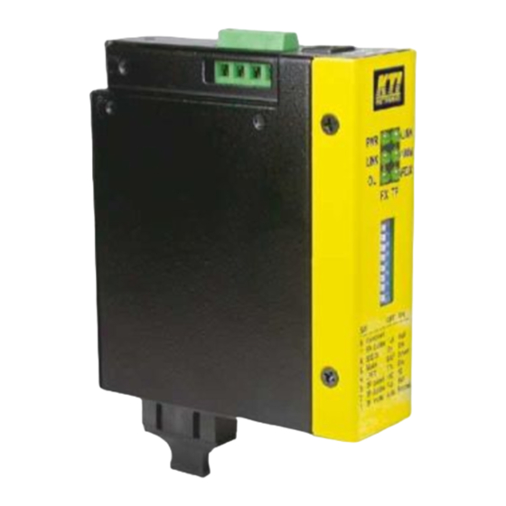
1.2 Specifications This figure shows the important components of the converter:... - Page 9 Twisted-Pair Interface (TP Port, or called copper Port) Connector Shielded RJ-45 Pin Assignments Auto MDI/MDI-X detection Signal Compliance IEEE 802.3 10BASE-T, 802.3u 100BASE-TX Data Speed 10Mbps or 100Mbps Duplex Mode Half-duplex or Full-duplex Configuration Auto-negotiation capable and optional forced manual settings Cable Types 10Mbps - Category 3, 4, or 5 UTP 100Mbps - Category 5 UTP...
- Page 10 Configuration Setting Switches (SW) FUNCTION SETTINGS TP Port mode Auto-negotiation (default) Forced mode TP Port Duplex Full duplex (default) Half duplex TP Port Speed 100Mbps (default) 10Mbps SW4 802.3x function Enable (default) Disable SW5 FX1 port duplex Full duplex mode (default) Half duplex mode SW6 FX2 port duplex Full duplex mode (default)
- Page 11 DC Power Input Interface Screw-type terminal block (2 sets for power wire cascading) DC Jack ( -D 6.3mm / + D 2.0mm) Operating Input Voltages +7V ~ +30V(+5%) Power consumption 2.7W max. @7.5VDC input 2.9W max. @24VDC input 3.0W max. @+30VDC input Basic Information MAC Addresses Entries Forwarding Throughput...
- Page 12 Certificate Part 15 Class B CE/EMC EMI EN50081-1 Class B EMS EN55024 CE/LVD Safety EN 60950 EN 50081-1/1992 : EN55022:1994/A1:1995/A2:1997 CISPR Class B EN61000-3-2:2000 Device <75W EN61000-3-3:1995/A1:2001 Clause 5 EN 55024:1998/A1:2001 IEC 61000-4-2:1995 ESD Test IEC 61000-4-3:1995 RS Test IEC 61000-4-4:1995 EFT/BURST Test IEC 61000-4-5:1995 Surge Test...
-
Page 13: Model Specifications
1.3 Model Specifications The media converter series provides the following fiber options: Model Specifications KCD-302-xxx WaveL. Operating Model Ext. FX Connectors (nm) Fiber Distance Temperature FX1 : ST MMF 1310 2 km -10 ~ 55 FX2 : ST MMF 1310... -
Page 14: Special Functions
1.4 Special Functions Auto MDI/MDI-X Function This function allows the TP port to auto-detect the twisted-pair signals and adapts itself to form a valid MDI to MDI-X connection with the remote connected device automatically. Auto-negotiation Function When TP port is set on Auto-negotiation mode (SW1:ON), it is featured with auto-negotiation function and full capability. -
Page 15: Installation
2. Installation 2.1 Unpacking Check that the following components have been included: • Information CD • The product unit • DIN-rail mounting bracket If any item is found missing or damaged, please contact your local reseller for replacement. The following are available optional accessories: •... -
Page 16: Din-Rail Mounting
2.2 DIN-Rail Mounting In the product package, a DIN-rail bracket is provided for mounting the converter in a industrial DIN-rail enclosure. The steps to mount the device onto a DIN-rail are: 1. Clamp the bracket into the rear of the device. Align the bracket with the rear face of the device and screw it onto the device unit. - Page 17 2. Unscrew and loose the mounting clamp plate of the bracket. Mount the bracket with the device onto the DIN rail. 5. Screw the clamp with the bracket and make sure the device is properly fixed on the DIN rail. -17-...
- Page 18 Make sure that there are proper heat dissipation from and adequate ven- tilation around the device. The final mechanical dimensions after installing DIN rail mounting bracket are: -18-...
-
Page 19: Mounting On A Plane Surface
2.3 Mounting on a Plane Surface An optional mounting bracket, as shown below is also available for mount- ing the device on a plane surface such as a wall, a wood board, or a metal plate in an industrial enclosure. To mount the device on a plane surface, the steps are: 1. - Page 20 2. Mount and screw the device on the target surface. The final dimension after bracket installation is also shown below: Make sure that there are proper heat dissipation from and adequate ven- tilation around the device. Do not place heavy objects on the device. -20-...
-
Page 21: Applying Power
2.4 Applying Power The product provide two types of power interfaces, terminal block and DC power jack for receiving DC power input from external power supply. DC Power Input Specification Operating Voltage +7 ~ +30VDC Power Consumption Max. 3.0W @30VDC DC Power Terminal Block Connectors Screw-type Terminal block (2 sets) - Page 22 DC2 + and DC2 - can be installed with another power-pair for delivering the main power input to next converter in a cascading way. Note: Only up to four device units can be cascaded to receive power from one main power input source. DC Power Jack Connector: Jack D 6.3mm...
-
Page 23: Making Tp Port Connection
2.5 Making TP Port Connection TP port is featured to support connection to : • Auto-negotiation devices • Auto-negotiation incapable 10BASE-T devices • Auto-negotiation incapable 100BASE-TX devices Network Cables 10BASE-T: 2-pair UTP Cat. 3,4,5 , EIA/TIA-568B 100-ohm STP 100BASE-TX: 2-pair UTP Cat. 5, EIA/TIA-568B 100-ohm STP Link distance: Up to 100 meters Note: The TP port is featured with auto MDI/MDI-X crossover... -
Page 24: Making Fx Port Connections
2.6 Making FX Port Connections FX1 port and FX2 port operate on 100Mbps and full duplex (factory default). A variety of fiber options is provided as follows: Model Specifications KCD-302-xxx WaveL. Operating Model Ext. FX Connectors (nm) Fiber Distance Temperature... -
Page 25: Optical Specifications
Optical Specifications KCD-302-xxx WaveL. TX Power Rx Sens. Rx max. Model Ext. FX Connectors (nm) (dBm) (dBm) (dBm) FX1 : ST MMF 1310 -19 ~ -14 -34 max. -14 min. FX2 : ST MMF 1310 -19 ~ -14 -34 max. -
Page 26: Configuration Switches & Led Indicators
3 Configuration Switches & LED Indicators The following figure shows the locations of the configuration switches and LED indicators: Refer to the following sections for the related functions. -26-... -
Page 27: Configuration Switches
3.1 Configuration Switches FUNCTION SETTING & STATE SW1 TP Port mode OFF Auto-negotiation (default) Forced mode SW2 TP Port Duplex OFF Full duplex (default) Half duplex SW3 TP Port Speed OFF 100Mbps (default) 10Mbps SW4 802.3x function OFF Enable (default) Disable SW5 FX1 port duplex OFF Full duplex mode (default) -
Page 28: Fx Port Duplex Settings Sw5 Sw6
3.1.3 FX Port Duplex Settings SW5 SW6 This settings are used to set the duplex mode of the FX1 port and FX2 port individually. It is recommended to use full duplex mode for FX con- nection unless its link partner is a fixed half duplex device. Half duplex mode will shorten the connection distance. -
Page 29: Led Indicators
3.2 LED Indicators DISPLAY STATUS & INTERPRETATION Power status Power on Power off LINK TP port link status Link up and no traffic Link fault Blink Rx/Tx activities 100M TP port speed status 100Mbps 10Mbps TP port duplex status Full duplex Half duplex Blink Collisions on half duplex LINK...
Need help?
Do you have a question about the KCD-302 Series and is the answer not in the manual?
Questions and answers