Table of Contents
Advertisement
This Manual is Bookmarked
Operating Instructions and Parts Manual
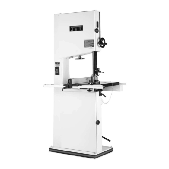
18-inch Metal/Wood Cutting Band Saw
Model VBS-18MW
WALTER MEIER (Manufacturing), Inc.
427 New Sanford Road
LaVergne, TN 37086-4184, USA
Part No. M-414418
Ph.: 800-274-6848
Revision B 10/09
www.waltermeier.com
Copyright © 2009 Walter Meier (Manufacturing), Inc.
Advertisement
Table of Contents

Related Manuals for Jet VBS-18MW


Summary of Contents for Jet VBS-18MW
- Page 1 This Manual is Bookmarked Operating Instructions and Parts Manual 18-inch Metal/Wood Cutting Band Saw Model VBS-18MW WALTER MEIER (Manufacturing), Inc. 427 New Sanford Road LaVergne, TN 37086-4184, USA Part No. M-414418 Ph.: 800-274-6848 Revision B 10/09 www.waltermeier.com Copyright © 2009 Walter Meier (Manufacturing), Inc.
-
Page 2: Warranty And Service
Walter Meier is consistently adding new products to the line. For complete, up-to-date product information, check with your local Walter Meier distributor, or visit jettools.com. WARRANTY JET products carry a limited warranty which varies in duration based upon the product (MW = Metalworking, WW = Woodworking). WHAT IS COVERED? This warranty covers any defects in workmanship or materials subject to the exceptions stated below. -
Page 3: Table Of Contents
Table of Contents Warranty and Service..........................2 Table of Contents ..........................3 Warning .............................4 Introduction ............................6 Specifications .............................6 Grounding Instructions ........................6 115 Volt Operation ..........................7 230 Volt Operation ..........................7 Extension cords..........................7 Unpacking ............................8 Contents of Shipping Container ......................8 Assembly ............................9 Handwheel............................9 Mounting the Table ..........................9 Rail Assembly ..........................9 Chip Tray ............................ -
Page 4: Warning
Warning 1. Read and understand the entire owner's manual before attempting assembly or operation. 2. Read and understand the warnings posted on the machine and in this manual. Failure to comply with all of these warnings may cause serious injury. 3. -
Page 5: Save These Instructions
20. Make your workshop child proof with padlocks, master switches or by removing starter keys. 21. Give your work undivided attention. Looking around, carrying on a conversation and “horse-play” are careless acts that can result in serious injury. 22. Maintain a balanced stance at all times so that you do not fall or lean against the blade or other moving parts. -
Page 6: Introduction
Introduction This manual is provided by Walter Meier (Manufacturing), Inc., covering the safe operation and maintenance procedures for a JET Model VBS-18MW Band Saw. This manual contains instructions on installation, safety precautions, general operating procedures, maintenance instructions and parts breakdown. This machine has been designed and constructed to provide years of trouble free operation if used in accordance with instructions set forth in this manual. -
Page 7: 115 Volt Operation
115 Volt Operation available or should be used with the 230V plug. The VBS-18MW band saw is wired from the factory for 115 volt operation. The power cord has a plug that looks like A, Figure 1, and is used in an outlet that looks like B, Figure 1. A... -
Page 8: Unpacking
Unpacking Contents of Shipping Container Band Saw Table Fence and Rail Assembly Resaw Guide and Knob Miter Gauge Upper Chip Tray Owner’s Manual Warranty Card Accessory Package Contains: Hardware Bag 2 Knobs 1 Handle 1 10/12mm Wrench 2 Screws, 1/4-20x1/4” (Upper Chip Tray) Fence Hardware Bag 4 Socket Head Cap Screws, 5/16x3/4”... -
Page 9: Assembly
Assembly Handwheel Attach the handle (A, Fig. 4) to the handwheel (B, Fig. 4). Mounting the Table Important: The table is heavy. The assistance of a second person is strongly recommended. Referring to Figures 5 and 6: Figure 4 1. Remove the table insert (A) and tapered pin (B). -
Page 10: Chip Tray
Chip Tray Referring to Figure 8: Insert two 1/4” x 1/4” pan head screws through the holes in the rear rail and into the table edge, leaving the screw heads protruding slightly. Mount the chip tray onto the screws as shown. Dust Collection Figure 8 If cutting wood on the band saw, attach the hose of... - Page 11 Fence Adjustment 5. Place the fence assembly onto the guide rail (D, Figure 11) and against the edge of the miter slot (C, Figure 11). The hook at the rear of the fence should fit under the rear rail (see Figure 14).
-
Page 12: Resaw Guide
Adjusting Clearance between Fence and Table Referring to Figures 13 and 14: Check the clearance between the table and the fence. The fence should not rub against the table surface but be slightly above it. This gap should be the same at the front of the table as it is at the rear. Figure 13 If the gap between fence and table is not consistent, loosen either of the hex nuts on the... -
Page 13: Adjusting 90 Degree Table Stop
Adjusting 90 Degree Table Stop Referring to Figures 17 and 18: Blade tension must be properly adjusted prior to adjusting 90 degree stop. Refer to the Adjusting Blade Tension section. 1. Loosen lock knobs (C) and tilt the table until it rests against the table stop bolt (B);... -
Page 14: Installing/Changing Blades
Installing/Changing Blades Referring to Figures 21 and 22: The band saw is provided with a 10-TPI metal cutting blade, 137”L x 3/4”W x 0.025”Thk. Disconnect machine from power source. Blade teeth are sharp, use care when handling the blade. Failure to comply may cause serious injury. -
Page 15: Blade Tension
Initially, set the blade tension to correspond to the width of your blade. The VBS-18MW comes with a 3/4" metal working blade, so the tension should be set at 3/4" on the metal working scale when using this blade. -
Page 16: Overview - Bearing Adjustments
Overview – Bearing Adjustments A Thrust (back support) bearing is located behind the saw blade and provides support to the back of the blade when the saw is in operation. Guide bearings are located on either side of the saw blade and provide stability for the blade when the saw is in operation. -
Page 17: Lower Bearing Adjustments
Lower Bearing Adjustments Unplug the machine from power source before making any adjustments! Blade teeth are sharp – use care when working near the saw blade. Failure to comply may cause serious injury. Note: Blade tension must be properly adjusted prior to bearing guide setup. -
Page 18: Blade Lead
Blade Lead Blade drift (also known as lead or fence drift) is a problem that may occur when the blade begins to wander off the cutting line even when the band saw fence is being used. Figure 28 shows an example of blade lead. -
Page 19: Replacing The V-Belt
Replacing the V-Belt Disconnect machine from power source before making any adjustments. Referring to Figures 29 and 30: 1. Release blade tension as described in the Blade Tension section. 2. Release belt tension by loosening the handle (A) and lifting up on the lever (B). Re-tighten the handle. -
Page 20: Pulley Alignment
Failure to comply may result in loss of property and/or serious injury. VBS-18MW is rated at 1-3/4 HP, 1Ph, 115/230V, prewired 115V. The band saw comes with a 115V plug. If you switch to 230V, a UL/CSA listed plug needs to be purchased for the band saw that matches the 230V outlet you intend to use. -
Page 21: Operation
Ripping Operation Ripping cutting lengthwise down workpiece, and with the grain (of wood stock). General Procedure See Figure 33. 1. Make sure the blade and upper and lower bearings are properly adjusted for tension and tracking. 2. Adjust blade guide assembly so that the guide bearings are just above the workpiece (about 3/16”) allowing minimum exposure to the blade. -
Page 22: Resawing
Resawing the tip of the tooth. Generally, wider blades are used for ripping or making straight cuts; Resawing is the process of slicing stock to narrower blades are often used when the part reduce its thickness, or to produce boards that being cut has curves with small radii. -
Page 23: Blade Breakage
A special type of saw lower wheel housings. Vacuum out frequently. blade is made from "high speed steel"; these Connect the band saw to a JET dust collection should not be used on band saws with low rates system. -
Page 24: Replacing Tires
4. Clean the surface of the drive wheels. Use a Replacing Tires solvent such as mineral spirits as required to achieve a clean, dry surface for the new The rubber tires that cover the drive wheels tires. protect the wheel from blade damage and provide a high friction drive force on the 5. -
Page 25: Blade Selection Guide
Blade Selection Guide Identify the material and thickness of your work piece. The chart will show the recommended PITCH, blade TYPE, and FEED RATE. Key: H – Hook L – Low S – Skip M – Medium R – Regular H –... -
Page 26: Blade Speed Per Materials Chart
Blade Speed per Materials Chart Speed range Material being cut (SF/M) Structural steel shapes Low carbon steel 160-165 Medium carbon steel High carbon steel 90-100 Cr-moly steel 105-135 Ni-Cr-moly steel 90-115 Chromium steel 80-140 Cr-vanadium steel 105-115 Tool steel 40-80 Stainless steel 40-70 Free machining steel... -
Page 27: Troubleshooting
Troubleshooting Trouble Probable Cause Remedy Saw stops or will not Saw unplugged. Check plug connections. start. Fuse blown, or circuit breaker tripped. Replace fuse, or reset circuit breaker. Cord damaged. Replace cord. Does not make Check blade with square and adjust Stop not adjusted correctly. - Page 28 Trouble Probable Cause Remedy Excessive blade Material loose in vise. Clamp work securely. breakage. Refer to charts on pages 25-26 or check Machinist’s Handbook for Incorrect speed or feed rate. speed/feed appropriate for the material being cut. Check Machinist’s Handbook for Teeth too coarse for material.
-
Page 29: Replacement Parts
Replacement Parts Replacement parts are listed on the following pages. To order parts or reach our service department, call 1-800-274-6848, Monday through Friday (see our website for business hours, www.waltermeier.com). Having the Model Number and Serial Number of your machine available when you call will allow us to serve you quickly and accurately. -
Page 30: Upper Wheel Assembly
Upper Wheel Assembly... -
Page 31: Parts List: Upper Wheel Assembly
37 ..TS-0590061 .....Wing Nut ............5/16-18 ....1 38 ..JWBS18-138 ....Lock Knob ............5/16 ......1 39 ..JWBS18DX-139 ....Upper Front Door................1 40 ..JWBS18-140 ....JET Nameplate................1 41 ..JWBS18-141 ....Warning Label ................1 42 ..JWBS18-142 ....Bolt ....................1 43 ..TS-0561011 .....Hex Nut............1/4-20 ...... 1 44 ..TS-081C052 .....Screw ............#10-24x3/4 .... -
Page 32: Lower Wheel And Motor Assembly
Lower Wheel and Motor Assembly... -
Page 33: Parts List: Lower Wheel And Motor Assembly
Parts List: Lower Wheel and Motor Assembly Index No. Part No. Description Size 1 ..JWBS18-201N....Bearing Base................1 2 ..JWBS20-62 ......Adjusting Bolt ................4 3 ..TS-0720091 .....Lock Washer ..........3/8 ......5 4 ..TS-0060081 .....Hex Cap Screw ..........3/8-16x1-3/4 ..... 4 5 ..BB-6204ZZ.......Ball Bearing..........6204ZZ ....1 6 ..VBS18MW-206....Spindle .................. - Page 34 51 ..TS-081C032 .....Screw ............#10-24x1/2 ....2 52 ..TS-1550031 .....Flat Washer..........M5 ......2 53 ..TS-0560071 .....Hex Nut............#10-24 ..... 2 54 ..JWBS18DX-254 ....Plastic Washer ..........5/16 ......1 55 ..TS-0720081 .....Lock Washer ..........5/16 ......6 56 ..TS-0561021 .....Hex Nut............5/16-18 ....2 57 ..VBS18MW-257....Lower Chip Tray ................1 58 ..TS-081F032 .....Pan Head Screw...........1/4-20x1/2 ....
-
Page 35: Blade Guide Assembly
Blade Guide Assembly... -
Page 36: Parts List: Blade Guide Assembly
Parts List: Blade Guide Assembly Index No. Part No. Description Size 1 ..TS-0051051 .....Hex Cap Screw ..........5/16-18x1 ....4 2 ..TS-0720081 .....Lock Washer ..........5/16 ......4 3 ..TS-0680031 .....Flat Washer..........5/16 ......8 4 ..JWBS18DX-304 ....Guide Bar Bracket ................ 1 5 ..JWBS18-305 ....Worm ................... 1 6 ..JWBS18-306 ....E-Ring ............E-8 ...... - Page 37 57 ..JWBS18DX-357 ....Bearing Bracket ................1 58 ..6295293......Locking Handle................1 59 ..JWBS18DX-359 ....Locking Handle................1 60 ..JWBS18DX-360 ....Shaft .................... 1 61 ..JWBS18DX-361 ....Adjusting Screw ................1 62 ..JWBS18DX-362 ....Adjusting Bracket................1 63 ..JWBS18DX-363 ....Nut ....................1 64 ..TS-0267021 .....Set Screw ............1/4-20x1/4 ....1 65 ..JWBS18DX-365 ....Set Screw, Special................
-
Page 38: Table And Fence Assembly
Table and Fence Assembly... -
Page 39: Parts List: Table And Fence Assembly
48 ..JWBS18DX-448 ....Table Pin..................1 49 ..JWBS18-449E ....Resaw Post .................. 1 50 ..JWBS18-450 ....Lock Knob ..................1 51 ..JWBS18-451 ....JET Fence Label ................1 52 ..TS-2210651 .....Hex Cap Screw ..........M10x65 ....1 53 ..TS-1551041 .....Lock Washer ..........M6 ......6 54 ..TS-1550041 .....Flat Washer..........M6 ......6... -
Page 40: Electrical Connections
57 ..TS-0051091 .....Hex Cap Screw ..........5/16-18x2 ....2 58 ..40-0260 ......Wrench ..................1 59 ..JWBS18DX-459 ....C-Ring ............S-10......1 60 ..JWBS18DX-460 ....Link Chain ..................1 61 ..TS-0680031 .....Flat Washer..........5/16 ......2 62 ..2013-285 ......End Cover ..................2 63 ..TS-081F032 .....Pan Head Screw...........1/4-20x1/2 ....2 64 ..VBS18MW-464....Upper Chip Tray ................
Need help?
Do you have a question about the VBS-18MW and is the answer not in the manual?
Questions and answers