
Related Manuals for Jet VBS-1207VS-DC


Summary of Contents for Jet VBS-1207VS-DC
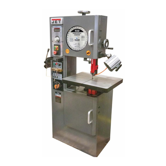
- Page 1 Operating Instructions and Parts Manual 12-inch Variable Speed Vertical Band Saw Model VBS-1207VS-DC Part No. M-JT1-1375 Edition 2 07/2024 Copyright © 2024 JET...
-
Page 2: Warranty And Service
JET sells through distributors only. The specifications listed in JET printed materials and on official JET website are given as general information and are not binding. JET reserves the right to effect at any time, without prior notice, those alterations to parts, fittings, and accessory equipment which they may deem necessary for any reason ®... -
Page 3: Table Of Contents
17.0 Replacement Parts ............................. 27 17.1.1 VBS-1207VS-DC Cabinet Assembly – Exploded View ............... 28 17.1.2 VBS-1207VS-DC Guide Post & Work Table Assembly – Exploded View ........... 29 17.1.3 VBS-1207VS-DC Drive System Assembly – Exploded View .............. 30 17.1.4 VBS-1207VS-DC Welder Assembly – Exploded View ................ 31 17.2.1 VBS-1207VS-DC Band Saw –... -
Page 4: Safety Warnings
5. Only use this band saw for its intended use. If used for other purposes, JET disclaims any 19. Always keep safety guards in place when the real or implied warranty and holds itself machine is in use. -
Page 5: About This Manual
If there are questions or comments, please contact your local supplier or JET. JET can also be reached at our web site: www.jettools.com. -
Page 6: Specifications
Shipping ..........................382 lbs (173.5kg) The specifications in this manual were current at time of publication, but because of our policy of continuous improvement, JET reserves the right to change specifications at any time and without prior notice, without incurring obligations. -
Page 7: Uncrating And Checking Contents
6.0 Uncrating and Checking 3. Use a forklift with sufficient lifting capacity and forks that are long enough to reach the Contents complete width of the machine. 4. Remove the securing bolts that attach the machine to the pallet. Suffocation Hazard! 5. -
Page 8: Anchoring The Machine
Volts Rating Cord in Feet properly grounded. More The VBS-1207VS-DC Band Saw is rated at 230V, More Than 60Hz alternating current. Verify the input power Than supply before making any electrical connections. Before connecting the machine to the power source, make sure the power source is OFF. -
Page 9: Product And Controls Identification
9.0 Product and Controls D - Blade Shear: Trims end of blade square prior to welding. Cuts saw bands ranging in width from Identification 0.062” to 1” (1.6mm to 25.4mm) and thickness of 0.025” to 0.035” (0.63mm to 0.89mm). E - Emergency Stop Switch: Removes power to OVERALL MACHINE the operating controls and stops operation. - Page 10 CONTROL PANEL WELD STATION Refer to Figure 9-2 Refer to Figure 9-3 Figure 9-2 Control Panel Identification A - Blade Speed Indicator: Displays the speed of the blade in FPM (Feet Per Minute). Figure 9-3 Weld Station Identification B - Speed Control: This potentiometer will vary A - Welder Controls: The pressure select the input signal, which in turn will vary the voltage switch is used to set the pressure or force used...
- Page 11 C – Upper Guide Post Handwheel: Turn TILTING WORK TABLE handwheel to raise or lower guide post. The work table may be tilted from 15° to 45°. D – Upper Guide Post: Provides blade guard The outboard side of the table will lift to create a protection and supports the blade.
-
Page 12: Adjustments
10.2 Blade Guide Adjustment 10.0 Adjustments Refer to Figure 10-2 All adjustments or repairs to Blade guides must be properly machine must be done with power off and adjusted or damage may occur to blade and/or machine disconnected from power source. guides. -
Page 13: Guide Post Adjustment
10.4 Changing Saw Blades Refer to Figure 10-4 1. Disconnect saw from power source. 2. Open the upper and lower pulley access doors. 3. Release the blade tension by rotating the tension wheel (A) counterclockwise. 4. Put on gloves to protect your hands. Now slide the blade off the upper and lower sheaves, around the blade guards, and through the slot in the table. -
Page 14: Tooth Shape
11.2 Tooth Shape 11.5 Breaking in a Band Saw Blade Note: When cutting thin materials, the rule for Sharp cutting edges with extremely small edge blade pitch is to have a minimum of two teeth radii are required for high cutting capacity. To engaging the material being cut at all times. -
Page 15: Band Saw Operation
The following body parts away from the saw blade. Use a procedure will be adequate for break-in of JET- block of wood as a pusher for the material supplied blades on lower alloy ferrous materials. -
Page 16: Basic Operating Procedure
12.6 Basic Operating Procedure 1. Verify the work area including the table is clear of obstructions. 2. Make sure upper and lower wheel housing doors are closed. There are door limit switches on each door which prevent the machine from operating if the doors are not closed. -
Page 17: Welder Operation
13.0 Welder Operation to be removed by grinding so that the weld area of the blade is uniform, and the teeth will be uniformly spaced (see Figure 13-2). The electrical current that Squaring Ends: If the saw band cut is not square after shearing, use the grinding wheel to square it flows through the blade welder when operating up. -
Page 18: Welding
13.2 Welding edge of right clamp. Slide the butt the end of blade against the other end of blade. Make sure the blade ends fit together with no gap The electrical current that (the blade ends need to be in contact with flows through the blade welder when operating each other). -
Page 19: Annealing
9. Release weld button (F) and wait 3 or 4 3. Quickly and repeatedly press the red anneal seconds until blade returns to original color. button (G) with a few short bursts to make the Unclamp blade. weld area a dull orangish-red. The wider the blade, the more bursts and time it will take. -
Page 20: Blade Grinding
13.3.2 Carbon Steel Hard Back Blades 1. Heat blade slowly until weld becomes a deep blue color. 2. Continue to heat by jogging the anneal button until the width of the blue color is one-half the length of the band exposed between the jaws. 3. -
Page 21: Maintenance
14.3 Monthly Maintenance 14.0 Maintenance Tighten any loose bolts, nuts, or screws on the machine. Before doing maintenance on Re-grease the drive bearings. the machine, disconnect it from the electrical Inspect the blade brush for wear. Adjust or replace supply. Failure to comply may cause serious if needed. -
Page 22: Troubleshooting
15.0 Troubleshooting 15.1 Driver Error Codes Table 2 Code Description Possible Cause Troubleshoot Problems Low voltage protection. Input voltage too low. Check the power supply. 1. Main power input over limit 1. Check main power voltage. voltage between 104- 2. Over motor allowance rate 120V(12”/18”), 208-230V Overload voltage protection. -
Page 23: Operating Problems
15.2 Operating Problems Table 3 Trouble Probable Cause Remedy Blade has been improperly welded. Re-weld blade. See Section 13.0 Welder Operation. Blade not installed properly. Follow instructions in Section 10.5 Changing Saw Blades. Saw blade is twisted. Feeding workpiece too forcefully. Decrease feed rate. -
Page 24: Mechanical And Electrical Problems
15.3 Mechanical and Electrical Problems Table 4 Trouble Probable Cause Remedy Machine will not Verify machine is connected to power start/restart, stops source. Make sure ON button is pushed in No incoming power. during operation, or completely, and STOP button is repeatedly trips circuit disengaged. -
Page 25: Welded Blade Inspection
15.4 Welded Blade Inspection Table 5 Trouble Probable Cause Remedy Weld is misaligned. Dirt or scale on welder jaws or blade. Always keep jaws clean. Clean blade before welding. Blade ends not square. Before welding, grind cut edges of blade until they are square. Use the shear on the band saw for square cuts. -
Page 26: Welder Mechanical Problems
15.5 Welder Mechanical Problems Table 6 Trouble Probable Cause Remedy Wire connection is poor; connecting Change switch or grind the connecting point of welding switch is bad. port with a file. Weld could not be Transformer burned out. Change transformer or rewire it. made. -
Page 27: Typical Band Saw Operations
Number of your machine available when you call will allow us to serve you quickly and accurately. Non-proprietary parts, such as fasteners, can be found at local hardware stores, or may be ordered from JET. Some parts are shown for reference only, and may not be available individually. -
Page 28: Vbs-1207Vs-Dc Cabinet Assembly - Exploded View
17.1.1 VBS-1207VS-DC Cabinet Assembly – Exploded View... -
Page 29: Vbs-1207Vs-Dc Guide Post & Work Table Assembly - Exploded View
17.1.2 VBS-1207VS-DC Guide Post & Work Table Assembly – Exploded View... -
Page 30: Vbs-1207Vs-Dc Drive System Assembly - Exploded View
17.1.3 VBS-1207VS-DC Drive System Assembly – Exploded View... -
Page 31: Vbs-1207Vs-Dc Welder Assembly - Exploded View
17.1.4 VBS-1207VS-DC Welder Assembly – Exploded View... -
Page 32: Vbs-1207Vs-Dc Band Saw - Parts List
17.2.1 VBS-1207VS-DC Band Saw – Parts List Index No Part No Description Size Cabinet Assembly 1 ....VBS1207VS-01 ..Lower Wheel Door ..................1 2 ....BSV12VS-V2-02 ..Hinge Pin Lower .................... 2 3 ....VBS1207VS-03 ..Motor Driver Board ..........1HP/ 110V ....1 3-1 ..... - Page 33 34 ....VBS1207VS-34 ..Acrylic Bracket-Left (Small) ................1 35 ....VBS1207VS-35 ..Acrylic Bracket-Right (Small) ................. 1 35-1 ... TS-2284082 ....Pan Head Machine Screw ........M4 x 8 ......2 35-2 ... TS-1540021 ....Hex Nut ..............M4 ......... 2 36 ....
- Page 34 Drive System Assembly 201 .... HN1/2 ......Hex Nut ..............1/2"-20 ......1 202 .... TS-0720111 ....Lock Washer ............1/2" ........ 1 203 .... BB6203 ..... Ball Bearing ............. 6203ZZ ......1 204 .... BSV12VS-V2-204 ..Int Retaining Ring ............ 35mm ......2 205 ....
- Page 35 Welder Assembly 301 .... TS-0050171 ....Hex Cap Screw ............1/4"-20 x 4" ....1 302 .... BSV20VS-V2-302 ..Transformer Bracket ..................1 303 .... TS-130005 ....Flat Washer ............. 1/4" ........ 2 304 .... TS-0561011 ....Hex Nut ..............1/4" x 20 ......2 305 ....
-
Page 36: Electrical Connections
18.0 Electrical Connections...
Need help?
Do you have a question about the VBS-1207VS-DC and is the answer not in the manual?
Questions and answers