Table of Contents
Advertisement
Quick Links
This .pdf document is bookmarked
Operating Instructions and Parts Manual
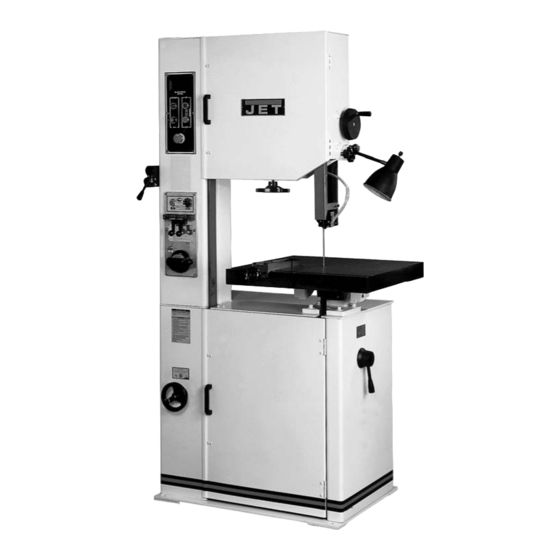
20-inch Metalworking Band Saw
Model VBS-2012
WALTER MEIER (Manufacturing) Inc.
427 New Sanford Road
LaVergne, Tennessee 37086
Part No. M-414482
Ph.: 800-274-6848
Revision G1 04/2013
www.waltermeier.com
Copyright © 2013 Walter Meier (Manufacturing) Inc.
Advertisement
Table of Contents

Related Manuals for Jet VBS-2012


Summary of Contents for Jet VBS-2012
- Page 1 This .pdf document is bookmarked Operating Instructions and Parts Manual 20-inch Metalworking Band Saw Model VBS-2012 WALTER MEIER (Manufacturing) Inc. 427 New Sanford Road LaVergne, Tennessee 37086 Part No. M-414482 Ph.: 800-274-6848 Revision G1 04/2013 www.waltermeier.com Copyright © 2013 Walter Meier (Manufacturing) Inc.
-
Page 2: Warranty And Service
Walter Meier Authorized Service Centers can authorize warranty repair, assist you in obtaining parts, or perform routine maintenance and major repair on your JET® tools. For the name of an Authorized Service Center in your area call 1-800-274-6848. -
Page 3: Table Of Contents
18.0 Replacement Parts ............................. 21 18.1.1 VBS-2012 Band Saw – Exploded View ....................22 18.1.2 VBS-2012 Band Saw (Welder Assembly) – Exploded View ............... 23 18.1.3 VBS-2012 Band Saw – Parts List ......................24 19.0 Electrical Connections ..........................29... -
Page 4: Safety Warnings
that are specifically designed to filter out microscopic particles. 10. Do not operate this machine while tired or under the influence of drugs, alcohol or any 3.0 Safety warnings medication. 11. Make certain the switch is in the OFF position 1. -
Page 5: About This Manual
This manual is provided by Walter Meier (Manufacturing) Inc. covering the safe operation and maintenance procedures for a JET Model VBS-2012 Band Saw. This manual contains instructions on installation, safety precautions, general operating procedures, maintenance instructions and parts breakdown. Your machine has been designed and constructed to provide years of trouble-free operation if used in accordance with the instructions as set forth in this document. -
Page 6: Specifications
5.0 Specifications Model number ............................VBS-2012 Stock number .............................. 414482 Blade speed ............................... variable Low range ............................... 65-555 High range ............................390-3280 Capacities: Height (max. thickness) ..........................12” Throat (max. width) ............................20” Welder capacity ..........................5/16” – 3/4" Motor ............TEFC, 2HP(1.5kW), 3PH, 230/460V (prewired 230V), 6.2/3.1A, 60Hz Table size ............................ -
Page 7: Uncrating And Assembly
Failure to comply may cause serious injury. diesel oil. Do not use gasoline, paint thinner, or any cellulose-based product, as these will The VBS-2012 Band Saw is rated at 230/460V and damage painted surfaces. comes from the factory prewired 230V. -
Page 8: Controls
control panel. Insert key and turn to 3 o’clock 9.0 Controls position to turn on power to control panel. Emergency Stop Switch (K, Figure 3) – Press to Low/High Range Shift Lever (B, Figure 2) – Pull stop all machine functions. Turn 90° to reset. toward front of machine to shift into low speed range. -
Page 9: Adjustments
Figure 6 Figure 4 Blade Tension Handwheel (S, Figure 5) – located Figure 7 on underside of upper frame. Turn clockwise to tension blade; counterclockwise to release tension 10.0 Adjustments on blade. Blade Tracking Handwheel (T, Figure 5) – located at upper rear of saw. Turn clockwise to All adjustments or repairs to track blade toward front of blade wheel. -
Page 10: Blade Tracking
4. Use blade tension indicator (D, Figure 9) as reference only. Blade should be tensioned using the finger pressure method. Figure 10 3. Loosen screw (G, Figure 10). Slide blade stop (H, Figure 10) toward blade until a gap of 1/32” remains. -
Page 11: Work Lamp Bulb
down toward table. NOTE: If teeth will not Carbide Tipped – for cutting unusual materials point downward regardless blade such as uranium, titanium, or beryllium. orientation, the blade is inside-out. Twist blade outside-in and reinstall. 11.2 Tooth shape 7. Verify that blade rests against ball bearing Note: When cutting thin materials, the rule for (Figure 11), not behind it. -
Page 12: Blade Breakage
• Run the bandsaw with blade centered in upper and lower guides, and guide fingers adjusted as close as possible without touching the blade or weld joint. Never adjust guide fingers while blade is running. Failure to comply may cause serious injury. 11.7 Blade breakage Band saw blades are subject to high stresses and breakage... -
Page 13: Annealing
2. Carefully clean ends of blade which will this time from the weld appearance. See contact welder jaws. Remove any dirt, oil, Figure 16 for examples of incorrect welds. scale and oxide. 11. If the weld is imperfect, refer to section 15.3 for possible remedies to any problems. -
Page 14: Blade Grinding
not break or crack after forming the radius. If 3. Follow this procedure before and after grinding the weld breaks, cut away welded area and bimetal blades. repeat welding-annealing process. 12.5 Blade grinding 6. Check to make sure welded section is same thickness as rest of blade. -
Page 15: Band Saw Operation
If chips are slightly curled and not colored by procedure will be adequate, however, for break-in heat, then the blade is sufficiently sharp and is of JET-supplied blades on lower alloy ferrous cutting at its most efficient rate. materials. 1. Use a section of round stock. -
Page 16: Troubleshooting
15.0 Troubleshooting 15.1 Operating problems Table 1 Trouble Probable Cause Remedy Blade has been improperly welded. Re-weld blade. See section 12.3 Blade not installed properly. Set guide inserts closer, and increase blade tension. Saw blade is twisted. Feeding workpiece too forcefully. Decrease feed rate. -
Page 17: Mechanical And Electrical Problems
15.2 Mechanical and electrical problems Table 2 Trouble Probable Cause Remedy Machine will not Verify machine is connected to power start/restart or source. Make sure START button is No incoming power. repeatedly trips circuit pushed in completely, and STOP button breaker or blows is disengaged. -
Page 18: Welded Blade Inspection
15.3 Welded blade inspection Table 3 Trouble Probable Cause Remedy Weld is misaligned. Dirt or scale on clamp jaws or blade. Always keep jaws clean. Clean blade before welding. Blade ends not square. Before welding, grind cut edges of blade until they are square. Use the shear on the band saw for square cuts. -
Page 19: Welder Mechanical Problems
15.4 Welder mechanical problems Table 4 Trouble Probable Cause Remedy Wire connection is poor; connecting Change switch, or grind the connecting point of welding switch is bad. port with a file. Weld could not be Transformer burned out. Change transformer, or rewire it. made. -
Page 20: Speed And Pitch Chart
16.0 Speed and pitch chart Table 5... -
Page 21: Typical Band Saw Operations
17.0 Typical Band Saw Operations Figure 20 18.0 Replacement Parts Replacement parts are listed on the following pages. To order parts or reach our service department, call 1- 800-274-6848 Monday through Friday (see our website for business hours, www.waltermeier.com). Having the Model Number and Serial Number of your machine available when you call will allow us to serve you quickly and accurately. -
Page 22: Vbs-2012 Band Saw - Exploded View
18.1.1 VBS-2012 Band Saw – Exploded View... -
Page 23: Vbs-2012 Band Saw (Welder Assembly) - Exploded View
18.1.2 VBS-2012 Band Saw (Welder Assembly) – Exploded View... -
Page 24: Vbs-2012 Band Saw - Parts List
18.1.3 VBS-2012 Band Saw – Parts List Index No Part No Description Size Qty Control Panel Assembly 6600 ..VBS2012-6600 ..Push Button - On ................... 1 6602 ..VBS2012-6602 ..Push Button – Off ..................1 6610 ..VBS2012-6610 ..Emergency Off Switch ................... 1 6650 .. - Page 25 Lower Wheel Assembly 3010 ..VBS1220A-301 ..Lower Wheel ....................1 3020 ..VBS-1220A-302 ..Rubber Tire ....................1 ....VBS2012-301 .... Lower Wheel with Tire ................... 1 3030 ..VBS2012-3030 ..Taper Sleeve ....................1 3040 ..
- Page 26 9300 ..VBS2012-9300 ..Upper Door Hinge ..................2 9999 ..VBS2012-9999 ..Eye Bolt ......................1 ....STRIPE-1-3/4 .... JET Stripe (not shown) ..........1-3/4”...... per ft. Variable Speed Assembly 7000 ..VBS2012-7000 ..Motor Spring Housing *.................. 1 7010 ..
- Page 27 7260 ..VBS2012-7260 ..Shaft Housing * ....................1 * ....VBS2012-7200CP ..Variable Speed Housing Assembly Complete ..........1 7290 ..VBS2012-7290 ..Wheel Seat ....................1 7300 ..VBS2012-7300 ..Pulley ......................1 7310 ..VBS2012-7310 ..Speed Readout Detector ................1 7320 ..
- Page 28 6250 ..PR-EV-6250 ....Switch * ......................1 6260 ..PR-EV-6260 ....Grinder Motor * ....................1 6270 ..PR-EV-6270 ....Spacer * ......................1 6280 ..PR-EV-6280 ....Grinding Wheel *.................... 1 6281 ..TS-0680021 ....Washer * ..............1/4" ........ 1 6282 ..
-
Page 29: Electrical Connections
19.0 Electrical Connections... - Page 30 This page intentionally left blank.
- Page 31 This page intentionally left blank.
- Page 32 WALTER MEIER (Manufacturing) Inc. 427 New Sanford Road LaVergne, Tennessee 37086 Phone: 800-274-6848 www.jettools.com www.waltermeier.com...
Need help?
Do you have a question about the VBS-2012 and is the answer not in the manual?
Questions and answers