Table of Contents
Advertisement
This .pdf document is bookmarked
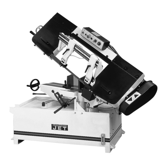
Operating Instructions and Parts Manual
10 x 14 Horizontal Mitering Band Saw
Model MBS-1014W
WALTER MEIER (Manufacturing) Inc.
427 New Sanford Road
LaVergne, Tennessee 37086
Part No. M-414477
Ph.: 800-274-6848
Revision G1 10/2013
www.jettools.com
Copyright © 2013 Walter Meier (Manufacturing) Inc.
Advertisement
Table of Contents

Subscribe to Our Youtube Channel
Related Manuals for Jet MBS-1014W


Summary of Contents for Jet MBS-1014W
- Page 1 This .pdf document is bookmarked Operating Instructions and Parts Manual 10 x 14 Horizontal Mitering Band Saw Model MBS-1014W WALTER MEIER (Manufacturing) Inc. 427 New Sanford Road LaVergne, Tennessee 37086 Part No. M-414477 Ph.: 800-274-6848 Revision G1 10/2013 www.jettools.com Copyright © 2013 Walter Meier (Manufacturing) Inc.
-
Page 2: Warranty And Service
JET, Wilton and Powermatic-branded websites are given as general information and are not binding. JET, Wilton and Powermatic reserve the right to effect at any time, without prior notice, those alterations to parts, fittings, and accessory equipment which they may deem necessary for any reason whatsoever. -
Page 3: Table Of Contents
14.1.1 Base and Bed Assembly – Exploded View ..................13 14.1.2 Bow Assembly – Exploded View ......................14 14.1.3 Parts List for MBS-1014W Band Saw ....................15 14.2.1 Gear Speed Reducer Assembly – Exploded View ................20 ... -
Page 4: Warnings
1. Read and understand the entire instruction manual before attempting assembly or 14. Keep visitors a safe distance from the work operation. area. 2. All JET bandsaws are designed and 15. Use recommended accessories; improper intended for use by properly trained and accessories may be hazardous. -
Page 5: About This Manual
This manual is provided by Walter Meier (Manufacturing) Inc. covering the safe operation and maintenance procedures for a JET Model MBS-1014W Horizontal Saw. This manual contains instructions on installation, safety precautions, general operating procedures, maintenance instructions and parts breakdown. Your machine has been designed and constructed to provide years of trouble-free operation if used in accordance with the instructions as set forth in this document. -
Page 6: Uncrating And Cleanup
8.0 Assembly 6.0 Uncrating and Cleanup 1. Unbolt the motor assembly from the shipping NOTE: Read and understand the entire manual crate bottom. before attempting setup or operation. 2. Remove nut (A, Figure 2) and washer (B, 1. Finish uncrating the saw and inspect for Figure 2) from the motor support shaft. -
Page 7: Electrical Connections
Failure to comply may cause serious injury. The MBS-1014W bandsaw is rated at 3HP, 3 phase 230/460V, prewired 230V; or 2HP, single phase, 230V only. Confirm power available at the saw’s location is the same as the saw is wired. To... -
Page 8: Adjustments
8. Check to see that coolant level is adequate Material chips or shavings are the best indicator of and turn on coolant pump if material to be cut proper speed and pressure. The ideal chip is thin, requires it. Machine should be filled with four tightly curled, and warm to the touch. -
Page 9: Blade Tracking Adjustment
6. Loosen lock knob (A, Figure 8) and slide left accomplished by qualified personnel that are blade guide arm (B, Figure 8) to the right as far familiar with this type of adjustment and the as possible. dangers associated with it. 1. -
Page 10: Thrust Roller Adjustment
12.7 Thrust roller adjustment 1. Disconnect machine from power source. 2. Loosen two hex socket cap screws (A, Figure 10). 3. Move guide seat (B, Figure 10) up or down until a clearance of 0.003” to 0.005” between back of blade and thrust roller is obtained. 4. -
Page 11: Angle Adjustment
1. Disconnect the machine from the power 12.10 Angle adjustment source. To swivel the saw arm up to a 45° angle: 2. Lower saw arm completely. 1. Disconnect the machine from the power 3. Pull the lock lever toward the front of the saw source. -
Page 12: Maintenance
2. Set the vise to desired angle, reinstall nuts and 2. Open drain plug and allow lubricant to drain tighten the nut and bolt assemblies. completely. Drain plug may be found on lower rear of gear case. Remove drain plug with a 3. -
Page 13: Base And Bed Assembly - Exploded View
14.1.1 Base and Bed Assembly – Exploded View... -
Page 14: Bow Assembly - Exploded View
14.1.2 Bow Assembly – Exploded View... -
Page 15: Parts List For Mbs-1014W Band Saw
14.1.3 Parts List for MBS-1014W Band Saw Index No Part No Description Size 1A ....MBS1014W-1A ..Base....................... 1 2 ....Ts-1492071 ....Hex Cap Bolt............M12x70 ......4 3 ....TS-1540081 ....Hex Nut ..............M12 ....... 4 4 .... - Page 16 Index No Part No Description Size 60 ....HBS1018W-60 ..Spring ......................1 62 ....TS-1492041 ....Hex Cap Bolt............M12x40 ......2 63-1 ... TS-1551081 ....Lock Washer (s/n 0202755 and lower) ....12mm ......6 ....TS-1551081 ....Lock Washer (s/n 0202756 and higher)....12mm ......2 65 ....
- Page 17 Index No Part No Description Size 110 .... HBS916W-110 ..Motor Mount Plate ..................1 111 .... HBS1018W-111 ..Motor................ 2HP, 1PH, 230V only ..1 ....MBS1014W-111 ..Motor................ 3HP, 3PH, 230/460V..1 ....HBS1018W-111A ..Capacitor (not shown)..........400MFD, 125VAC ..1 ....
- Page 18 Index No Part No Description Size 158 .... HBS916W-158 ..Lock Knob ...................... 2 159 .... TS-1523021 ....Set Screw ..............M6x8 ......1 160 .... HBS916W-160 ..Adjusting Valve ....................2 160-1 ..HBS916W-160-1 ..Clamp ......................2 160-2 ..
- Page 19 Index No Part No Description Size 220A ..MBS1014W-220A ..Support (S/N 0202756 and higher) ..............1 221 .... MBS1014W-221 ..Adjustable Handle..................1 222 .... MBS1014W-222 ..Bracket......................1 223 .... MBS1014W-223 ..Bracket......................1 224 ....
-
Page 20: Gear Speed Reducer Assembly - Exploded View
14.2.1 Gear Speed Reducer Assembly – Exploded View... -
Page 21: Gear Speed Reducer Assembly - Parts List
14.2.2 Gear Speed Reducer Assembly – Parts List Index No Part No Description Size 1 ....HBS916W-94-01 ..Oil Seal ..............35x55x8 mm ....1 2 ....BB-30207 ....Bearing ..............30207 ......1 3 ....BB-6207 ....Bearing ..............6207 ......1 4 .... -
Page 22: Electrical Connections
15.0 Electrical Connections 15.1.1 Electrical Connections – 1 Phase 15.1.2 Electrical Panel Layout – 1 Phase... -
Page 23: Electrical Connections - 3 Phase
15.2.1 Electrical Connections – 3 Phase 15.2.2 Electrical Panel Layout – 3 Phase... - Page 24 WALTER MEIER (Manufacturing) Inc. 427 New Sanford Road LaVergne, Tennessee 37086 Phone: 800-274-6848 www.jettools.com...
Need help?
Do you have a question about the MBS-1014W and is the answer not in the manual?
Questions and answers