Table of Contents
Advertisement
Advertisement
Table of Contents
Troubleshooting

Related Manuals for Jet VBS-3612


Summary of Contents for Jet VBS-3612
- Page 1 This Manual is Bookmarked Operating Instructions and Parts Manual 36-inch Metalworking Band Saw Model VBS-3612 WMH TOOL GROUP 2420 Vantage Drive Elgin, Illinois 60124 Part No. M-414470A Ph.: 800-274-6848 Revision A1 9/06 www.wmhtoolgroup.com Copyright © WMH Tool Group...
-
Page 2: Warranty And Service
Warranty and Service WMH Tool Group, Inc., warrants every product it sells. If one of our tools needs service or repair, one of our Authorized Service Centers located throughout the United States can give you quick service. In most cases, any of these WMH Tool Group Authorized Service Centers can authorize warranty repair, assist you in obtaining parts, or perform routine maintenance and major repair on your JET tools. -
Page 3: Table Of Contents
Speed and Pitch Chart...23 Typical Band Saw Operations ...24 Troubleshooting – Mechanical and Electrical Problems ...26 Replacement Parts ...29 Parts List: VBS-3612 Band Saw ...30 VBS-3612 Band Saw...35 VBS-3612 Band Saw...36 Parts List: Welder, Shear and Work Lamp Assemblies...37 Welder, Shear and Work Lamp Assemblies...39 Electrical Connections –... -
Page 4: Warning
4. This band saw is designed and intended for use by properly trained and experienced personnel only. If you are not familiar with the proper and safe operation of a band saw, do not use until proper training and knowledge have been obtained. -
Page 5: Save These Instructions
33. Always wear leather gloves when handling saw blades. The operator should not wear gloves when operating the machine. 34. Do not allow the saw blade to rest against the workpiece when the saw is not running. 35. The saw must be stopped and the electrical supply must be cut off before any blade replacement, drive belt replacement, or any periodic service or maintenance is performed on the machine. -
Page 6: Introduction
This manual is provided by WMH Tool Group covering the safe operation and maintenance procedures for a JET Model VBS-3612 Band Saw. This manual contains instructions on installation, safety precautions, general operating procedures, maintenance instructions and parts breakdown. This machine has been designed and constructed to provide years of trouble free operation if used in accordance with instructions set forth in this manual. -
Page 7: Features And Terminology
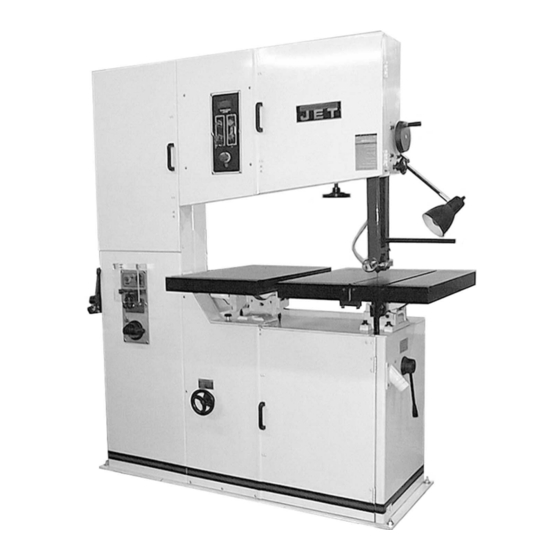
Features and Terminology 1 – Main Work Table 2 – Work Lamp 3 – Blade Tension Handwheel 4 – Auxiliary Work Table 5 – Variable Speed Handwheel 6 – Chip Port 7 – Gear Shift Lever 8 – Rod for Circle Cutting Attachment 9 –... -
Page 8: Unpacking
Open shipping container and check for shipping damage. Report any damage immediately to your distributor and shipping agent. Do not discard any shipping material until the Band Saw is set up and running properly. Compare the contents of your container with the following parts list to make sure all parts are intact. -
Page 9: Installation And Assembly
Use a forklift with a strap or chain connected to the eye bolt to lift the band saw from the pallet. Move the band saw to its permanent location which should be dry, well ventilated, with sufficient lighting. -
Page 10: Grounding Instructions
Extension cords extension recommended for this Band Saw. But if one is necessary, make sure the cord rating is suitable for the amperage listed on the machine’s motor plate. An undersize cord will cause a drop in line... -
Page 11: Converting From 230 Volt To 460 Volt (Three Phase)
If the Band Saw is to be hard-wired to a panel, make sure a disconnect is available for the operator. During hard-wiring of the Band Saw, make sure the fuses have been removed or the breakers have been tripped in the circuit to which the Band Saw will be connected. -
Page 12: Blade Tension
If the band saw is not to be used for a period of time, release tension on the blade – this will prolong its life. First make a note of the specific tension setting for that blade. -
Page 13: Guide Post
The stopper positioned behind the back edge of the blade (Figure 10) will also become worn with use, and the friction of the shaft with the saw blade may cause lines in the surface of the stopper. If this occurs, loosen the socket head cap screw, and rotate the stopper to either side to change its position on the blade. -
Page 14: Squaring Work Table With Blade
Squaring Work Table with Blade 1. Place the table in horizontal position with “0” on the scale (Figure 11). 2. Place a machinist’s square on the table and against the blade as shown. 3. If the square is not flush against the blade, loosen the screw below the table (Figure 11) with a 26mm wrench (provided). -
Page 15: Work Lamp Bulb
JET-supplied blades on lower alloy ferrous materials. 1. Use a section of round stock. 2. Operate the saw at low speed. Start the cut with a very light feed rate. 3. When the saw has completed about 1/3 of the cut, increase the feed rate slightly and allow the saw to complete the cut. -
Page 16: Evaluating Cutting Efficiency
Shearing Cut the blade to the longest length needed for the band saw. Using the shear to cut your blade will ensure that the blade ends are cut flat, square and smooth. 1. Place the blade in the shear as shown in Figure 15. -
Page 17: Removing Teeth
IMPORTANT: If a blade has been cut by using snips, the ends of the blade must be ground square before welding them together, as shown in Figure 17. Removing Teeth In fine pitched blades, one or more of the teeth on each side of the cut may need to be removed by grinding so that the weld area of the blade is uniform and the teeth will be uniformly spaced. -
Page 18: Annealing
The size of the radius should be approximately the same as the radius of the band saw drive wheel. The weld must hold and not break or crack after forming the radius. If the weld breaks, cut away the welded area and repeat the welding- annealing process. -
Page 19: Blade Selection
5. the “set” of the teeth 6. the blade material itself Width Band saw width is measured from the back of the blade to the tip of the tooth. Always use the widest blade possible that still performs the needed job. Generally, wider blades are used for straight cutting. -
Page 20: Gage
Gage Use the standard gage (blade thickness) except when the increased thickness of the workpiece decreases accuracy and width cannot be increased to compensate. Examples of heavy gage applications: 1. When radius cutting in thick materials. 2. When the maximum width usable on the machine still provides insufficient beam strength for the blade. -
Page 21: Set
The term “set” refers to the way in which the saw teeth are bent or positioned. Bending the teeth creates a kerf that is wider than the back of the blade. -
Page 22: Maintenance
Maintenance Before doing maintenance on the machine, disconnect it from the electrical supply by pulling out the plug or switching off the main switch! Failure to comply may cause serious injury. Use a brush to loosen accumulated chips and debris. Use a shop vacuum to remove the debris. -
Page 23: Speed And Pitch Chart
Speed and Pitch Chart... -
Page 24: Typical Band Saw Operations
Typical Band Saw Operations... -
Page 25: Troubleshooting - Operating Problems
Dull blade. Guide post not fixed properly. Blade warps. Blade not tensioned enough. Blade not 90° to table. Band Saw not resting on level Band Saw is noisy, or surface. vibrates too much. The variator pulley is damaged. Incorrect blade for the job. -
Page 26: Troubleshooting - Mechanical And Electrical Problems
Check amp setting on motor starter. Verify that band saw is on a circuit of correct size. If circuit size is correct, there is probably a loose electrical lead. - Page 27 Miswiring of the unit. repeatedly trips circuit breaker or blows fuses. Switch failure. Band Saw does not Extension cord too light or too long. come up to speed. Low current. Remedy If electric motor is suspect, you have...
- Page 28 Remedy Always keep jaws clean. Clean blade before welding. Before welding, grind cut edges of the blade until they are square. Use the shear on the band saw for square cuts. Align the ends properly before clamping. Replace clamp jaws.
-
Page 29: Replacement Parts
Troubleshooting – Welder Mechanical Problems Trouble Probable Cause Wire connection is poor; connecting point of welding switch is bad. Weld could not be Transformer burnt out. made. Jaws do not move. Blade has oil on it. Blade ends have rust on them. Welding switch is cutting off too late. -
Page 30: Parts List: Vbs-3612 Band Saw
Parts List: VBS-3612 Band Saw (refer to breakdowns on pages 35 and 36) Index No. Part No. Description 1...VBS3612-101... Gear Box ..1 2...TS-0209101 ... Socket Head Cap Screw... 3/8”-16 x 2-1/4” ... 4 3...TS-0720091 ... Lock Washer... 3/8"... 26 4...TS-0680041 ... - Page 31 Index No. Part No. Description Size 56 ...TS-0561021 ... Hex Nut ... 5/16”-18... 4 57 ...VBS1220M-110... Guide Support Housing..1 58 ...TS-0208061 ... Socket Head Cap Screw... 5/16”-18 x 1" ... 4 59 ...TS-0720081 ... Lock Washer... 5/16"... 34 60 ...TS-0680031 ...
- Page 32 Index No. Part No. Description Size 115 ...TS-0051051 ... Hex Cap Screw... 5/16”-18 x 1" ... 8 116 ...VBS3612-1116... Motor Pulley ... 4-1/8” A3... 1 117 ...VB-A44 ... V-Belt ... 2010+7070 ... 2 118 ...VB-A50 ... V-Belt ... 7300+7071 ... 2 119 ...BA62...
- Page 33 Index No. Part No. Description Size 174 ...VBS3612-1174... Spring Plate..6 175 ...VBS3612-1175... Handle Arm ..3 176 ...TS-1534052 ... Phillips Pan Head Machine Screw... M6 x 16 ... 6 177 ...TS-1540041 ... Hex Nut ... M6 ... 6 178 ...9600...
- Page 34 Index No. Part No. Description Size 233 ...TS-0267061 ... Set Screw... 1/4"-20 x 5/8"... 4 234 ...VBS2012-7100... Gear Shaft ..1 235 ...VBS2012-7110... Worm..1 236 ...TS-0267041 ... Socket Set Screw ... 1/4"-20 x 3/8"... 1 237 ...VBS2012-7120... Arm ..1 238 ...VBS2012-7190...
-
Page 35: Vbs-3612 Band Saw
VBS-3612 Band Saw... -
Page 36: Vbs-3612 Band Saw
VBS-3612 Band Saw... -
Page 37: Parts List: Welder, Shear And Work Lamp Assemblies
Parts List: Welder, Shear and Work Lamp Assemblies (refer to breakdown on page 39) Index No. Part No. Description Size 1...JWG34-601... Limit Switch ..1 2...PR-EV-6011... Insulator ..1 3...VBS3612-203... Pan Head Bolt ... 1/8”-32 x 5/8" ... 2 4...TS-0720051 ... - Page 38 Index No. Part No. Description Size 58 ...PR-EV-6280... Grinder Wheel ..1 59 ...TS-0680021 ... Flat Washer ... M6 ... 1 60 ...TS-1540041 ... Hex Nut ... M6 ... 1 61 ...VBS1220M-629... Grinder Guard..1 62 ...PR-EV-6291... Grinder Cover..1 63 ...JWG34-633...
-
Page 39: Welder, Shear And Work Lamp Assemblies
Welder, Shear and Work Lamp Assemblies... -
Page 40: Electrical Connections - 3Ph, 230/460V
Electrical Connections – 3Ph, 230/460V... -
Page 41: Electrical Connections - 3Ph, 230/460V
Electrical Connections – 3Ph, 230/460V Weld On (White) Anneal On (Green) Emergency Stop (Red) Main Motor Off (Red) Main Motor On (Green) Grinder Motor On Work Lamp On (Black) Key Switch Indicator Light (Green) Lamp (60W, 115V) General Switch Safety Switch Safety Switch Weld Auto Stop Safety Switch... -
Page 42: Electrical Box
Electrical Box (see page 41 for identification of parts) - Page 44 WMH Tool Group 2420 Vantage Drive Elgin, Illinois 60124 Phone: 800-274-6848 www.wmhtoolgroup.com...
Need help?
Do you have a question about the VBS-3612 and is the answer not in the manual?
Questions and answers