Table of Contents

Related Manuals for Jet VBS-18MWEVS


Summary of Contents for Jet VBS-18MWEVS
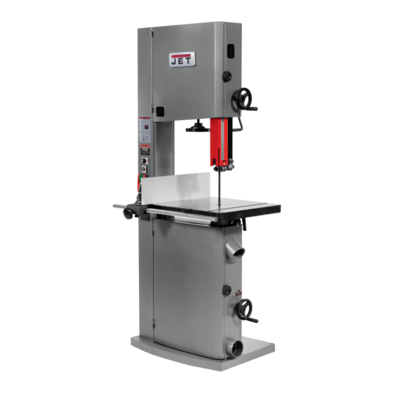
- Page 1 Operating Instructions and Parts Manual Metal/Wood Working MWEVS Band Saw Model VBS-18MWEVS 427 New Sanford Road LaVergne, Tennessee 37086 Part No. M-414428 Ph.: 800-274-6848 Edition 1 06/2021 www.jettools.com Copyright © 2021 JET...
-
Page 2: Important Safety Instructions
Do not use this band saw for other than its 21. Give your work undivided attention. Looking intended use. If used for other purposes, JET around, carrying on a conversation and “horse- disclaims any real or implied warranty and holds play”... - Page 3 29. Remove loose items and unnecessary work 42. Don’t use in dangerous environment. Don’t use pieces from the area before starting the power tools in damp or wet location or expose machine. them to rain. Keep work area well lighted. 30.
-
Page 4: Table Of Contents
1.0 IMPORTANT SAFETY INSTRUCTIONS ....................2 2.0 Table of contents ............................ 4 3.0 About this manual ..........................6 4.0 Specifications for VBS-18MWEVS ......................7 4.1 Overall Dimensions ..........................8 5.0 Setup and Assembly ..........................9 5.1 Shipping contents ........................... 9 5.2 Tools required for assembly ....................... - Page 5 18.9.1 VBS-18MWEVS Upper Blade Guide Assembly – Exploded View ..........47 18.9.2 VBS-18MWEVS Upper Blade Guide Assembly – Parts List ............47 18.10.1 VBS-18MWEVS Speed control & Switch assembly – Exploded View ........48 18.10.2 VBS-18MWEVS Speed control & Switch assembly – Parts List ..........48 18.11.1 VBS-18MWEVS AC Inverter Assembly –...
-
Page 6: About This Manual
Additional knowledge can be obtained from experienced users or trade articles. Whatever accepted methods are used, always make personal safety a priority. If there are questions or comments, please contact your local supplier or JET. JET can also be reached at our web site: www.jettools.com. -
Page 7: Specifications For Vbs-18Mwevs
4.0 Specifications for VBS-18MWEVS Model number ............................VBS-18MWEVS Stock number ..............................414428 Band saw nominal size ............................18 in. Motor and electricals: Motor type ................totally-enclosed, powered fan-cooled, iron motor housing Horsepower ................................2 HP Phase ..................................three Voltage .................................. -
Page 8: Overall Dimensions
Subject to local/national electrical codes. The specified values are emission levels and are not necessarily to be seen as safe operating levels. As workplace conditions vary, this information is intended to allow the user to make a better estimation of the hazards and risks involved only. 4.1 Overall Dimensions Figure 4-1: base hole centers (millimeters) -
Page 9: Setup And Assembly
5.0 Setup and Assembly Read and understand the entire contents of this manual before attempting assembly or operation. Failure to comply may cause serious injury. Figure 5-1B: contents 5.1 Shipping contents 5.2 Tools required for assembly Refer to Figure 5-1A and 5-1B. The tools listed below are not included but are required for assembly. -
Page 10: Installing And Aligning Table
5.6 Installing and aligning table Table is heavy. Mounting with the help of another person is recommended. Refer to Figures 5-3 through 5-4: Slide table so that saw blade passes through slot (A). Line up table to trunnions and insert four hex cap screws with lock washers and flat washers Figure 5-5 (Figure 5-4). -
Page 11: Miter Gauge
Tighten screw. immediately. 6.2 Single phase connections Model VBS-18MWEVS Band Saw is wired from the factory for 230 Volt, single phase operation. It is not supplied with a plug. You may either install a UL/CSA-listed plug suitable for 230 Volt operation, or “hard-wire”... -
Page 12: Circuit Information
Slide fence to approximate position, based on Recommended the scale measurement aligning with the right Model Voltage Circuit* side of resaw fence. 414428, VBS-18MWEVS 230 V Tighten knob (B). * Local codes take precedence over Rotate knurled knob (C) to achieve fine recommendations. adjustment. -
Page 13: Adjusting 90-Degree Table Stop
7.4 Adjusting 90-degree table stop Move quick tension lever to “Full Release (Blade Change)” position. Before adjusting the 90º table stop, the blade Open upper and lower doors by rotating door tension must be properly adjusted (see sect. 7.7) knobs. To adjust 90º... -
Page 14: Blade Tension
Figure 7-9 Figure 7-8 11. Position blade at center of upper and lower wheels. 12. Reinstall dust block (J, Figure 7-8) and table slot handle (HP6, Figure 5-3). 13. Before operating band saw, the new blade must be tensioned and tracked, in that order. Find instructions for tensioning and tracking the blade in sections 7.7 and 7.9. -
Page 15: Blade Tracking
7.9 Blade tracking Loosen locking handle (P, Figure 7-12) and slightly rotate tracking knob (R) with your right Refer to Figures 7-12 and 7-13. hand while continuing to rotate wheel with your left. Observe blade through tracking window. After proper tensioning, the blade must be tracked. Rotating knob clockwise will cause blade to “Tracking”... -
Page 16: Upper Thrust Bearing
NOTE: Do not force guide bearing against side of blade. It should generally only make contact with blade when there is pressure from the cutting operation. Tighten lock knob (B). 10. Repeat process for opposite guide bearing. 7.12 Upper thrust bearing Refer to Figures 7-14 and 7-15. -
Page 17: Guide Post
7.15 Guide post parallelism The guide post should be parallel to blade throughout vertical travel of the guide post; thus the guide bearings will maintain their relationship to blade at any height from the table and won’t require re-setting each time guide post is moved. This setting been accurately... - Page 18 Depending on the desired cutting application, this This is done by changing the positioning and band saw can be set for either “Wood Cutting” mode configuration of the belt(s) to match the desired with a speed range of 540-3600 SFPM (with wood mode of operation.
-
Page 19: Operating Controls
8.0 Operating Controls Tighten the lock handle to hold the motor in the down position when tension is correct. 10. When complete, the belt routing will match 8.1 Start/Stop Switch Figure 7.20. Refer to Figure 8-1. 11. Complete the change to “Wood Mode” by installing the correct blade and changing the Insert the key into the power switch (C) and turn display to Wood Mode. -
Page 20: Setting Speed Digital Readout
8.3 Variable Speed Control Dial NOTE: When the key switch is turned Off, it is common and normal for the display to show an LV The variable speed control dial (D, Figure 8-1) (Low Voltage) code. Additionally, when the key will adjust the blade speed during operation. -
Page 21: Ripping
Turn on band saw and allow a few seconds for the machine to reach full speed. Whenever possible, use a push stick, hold-down, power feeder, jig, or similar device while feeding stock, to prevent your hands getting too close to the blade. Place the straightest edge of the workpiece against the fence and push the workpiece slowly into the blade. -
Page 22: Operation - Metal
There are five specific blades on specific materials. The following (5) blade features that are normally changed to meet procedure will be adequate, however, for break-in of certain kinds of sawing requirements. JET-supplied blades lower alloy ferrous materials. -
Page 23: Width
• the "set" of the teeth • the blade material itself. 11.1 Width Band saw blades come in different standard widths, measured from the back of the blade to the tip of the tooth. Generally, wider blades are used for ripping or making straight cuts;... -
Page 24: Material
Straight Set – used for free cutting non-ferrous from "high speed steel"; these should not be used materials; i.e., aluminum, magnesium, plastics, and on band saws with low rates of speed. wood. Carbon Steel – low cost, for use with non-ferrous Wavy Set –... -
Page 25: Non-Metal Blade Chart
12.0 Non-Metal Blade Chart Identify the material and thickness of your workpiece. Table 3 will show the recommended PITCH, blade TYPE, and FEED RATE. Key: H – Hook L – Low S – Skip M – Medium R – Regular H –... -
Page 26: Speed And Pitch Chart - Metal
13.0 Speed and Pitch Chart – Metal Table 4... -
Page 27: Typical Band Saw Operations
14.0 Typical Band Saw Operations... -
Page 28: User-Maintenance
Clean band saw regularly to remove any resinous way, have it replaced immediately. deposits and sawdust. Connect the band saw to a JET dust collection Keep miter slot, and guide bearings, clean and free system of appropriate capacity. of resin. -
Page 29: Troubleshooting Vbs-18Mwevs Band Saw
16.0 Troubleshooting VBS-18MWEVS Band Saw 16.1 Operational problems Table 5 Symptom Probable Cause Correction * Lock handle not tight. Tighten lock handle. Table tilt does not hold Trunnion locking mechanism is broken Replace trunnion locking mechanism. position under load. or worn. - Page 30 Symptom Probable Cause Correction * Blade pitch too coarse. Refer to blade selection chart; use finer pitch blade. Blade breaks Guide bearings not properly supporting Check guide bearings for correct prematurely. blade. position and signs of wear. Adjust or replace as needed. Blade tensioned too tightly.
-
Page 31: Mechanical And Electrical Problems
16.2 Mechanical and electrical problems Table 6 Symptom Probable Cause Correction * No incoming power. Verify machine connections. Cord damaged. Replace cord. Band Saw frequently trips. One cause of overloading trips which are not electrical in nature is too heavy a cut. -
Page 32: Replacement Parts
Non-proprietary parts, such as fasteners, can be found at local hardware stores, or may be ordered from JET. Some parts are shown for reference only and may not be available individually. -
Page 33: Vbs-18Mwevs Mw/Ww Band Saw Assembly - Exploded View
18.1.1 VBS-18MWEVS MW/WW Band saw Assembly – Exploded View... -
Page 35: Vbs-18Mwevs Ww/Mw Band Saw Assembly - Parts List
18.1.2 VBS-18MWEVS WW/MW Band saw Assembly – Parts List Index No. Part No. Description Size PM1500-004 ..... Lifting Ring ............M10 ........ 1 VBS-18MWEVS-002 ..Machine Main Body Frame ..............1 TS-1482021 ...... Hex Cap Bolt ............. M6x12 ......1 TS-1533032 ...... - Page 36 VBS-18MWEVS-085CF ..Motor Coolant Fan (not shown) ............1 VBS-18MWEVS-085CFC ..Motor Fan Cover (not shown) ............... 1 VBS-18MWEVS-085JB ..Junction Box with Cover (not shown) ........... 1 PM1500-015 ......Motor Bracket Lock Handle ......M10x33 ......1 TS-1550071 ......
- Page 37 TS-2279301 ....Set Screw ............. M10x30 ....... 4 TS-1541041 ....Hex Nut ..............M10 ......4 VBS-18MWEVS-093 ..Lower Wheel Shaft ................... 1 JWBS15-197 ....Motor Bracket Handle ................1 PM1500-039 ....Tapping Screw ............. M4x8 ......2 TS-1540061 ....
- Page 38 VBS-18MWEVS-151 ..Bearing Stand Assembly ................1 TS-2361101 ....Lock Washer ............M8 ....... 2 VBS-18MWEVS-153 ..Metal Working Saw Blade ........150”x3/4”x0.03”x8TPI . 1 TS-1490031 ....Hex Cap Screw ............ M8x20 ......2 VBS-18MWEVS-155 ..Motor Pulley ..................... 1 VBS-18MWEVS-156 ..
-
Page 39: Vbs-18Mwevs Trunnion Support Bracket Assembly - Exploded View
18.2.1 VBS-18MWEVS Trunnion Support Bracket Assembly – Exploded View... -
Page 40: Vbs-18Mwevs Trunnion Support Bracket Assembly - Parts List
18.2.2 VBS-18MWEVS Trunnion Support Bracket Assembly – Parts List Index No Part No Description Size JWBS15-1138A ..... Trunnion Support Bracket Assembly (#1 thru 34) ........TS-1550061 ....Flat Washer ............M8 x Ø23 ....2 TS-2361081 ....Lock Washer ............M8 ....... 1 TS-1541031 .... -
Page 41: Vbs-18Mwevs Rip Fence Assembly - Exploded View
18.3.1 VBS-18MWEVS Rip Fence Assembly – Exploded View 18.3.2 VBS-18MWEVS Fence Assembly – Parts List Index No. Part No. Description Size JWBS18B-1128 ..... Rip Fence Assembly (#1 thru 18) .............. JWBS15-1123-201 ..Fence Body ....................1 JWBS15-1123-202 ..Lock Block ....................1 JWBS18B-1128-203 .. -
Page 42: Vbs-18Mwevs Miter Gauge Assembly - Exploded View
18.4.1 VBS-18MWEVS Miter Gauge Assembly – Exploded View 18.4.2 VBS-18MWEVS Miter Gauge Assembly – Parts List Index No Part No Description Size JWBS15-1122 ....Miter Gauge Assembly (#1 thru 9) ............. JWBS15-1122-701 ..Guide Bar ....................1 JWBS15-1122-702 ..Guide Piece....................1 JWBS15-1122-703 .. -
Page 43: Vbs-18Mwevs Guide Bar Bracket Assembly - Exploded View
18.5.1 VBS-18MWEVS Guide Bar Bracket Assembly – Exploded View 18.5.2 VBS-18MWEVS Guide Bar Bracket Assembly – Parts List Index No Part No Description Size JWBS18B-1125 ..... Guide Bar Bracket Assembly (#1 thru 28) ..........JWBS18B-1125-401 ..Guide Bar ....................1 TS-1503021 .... -
Page 44: Vbs-18Mwevs Upper Wheel Assembly - Exploded View
JWBS18B-1125-426 ..Plate ......................2 JWBS18B-1125-427 ..Nylon Piece ....................2 JWBS15-1120-425 ..Plastic Nylon Set Screw ........M7x10 ......4 18.6.1 VBS-18MWEVS Upper Wheel Assembly – Exploded View 18.6.2 VBS-18MWEVS Upper Wheel Assembly – Parts List Index No Part No... -
Page 45: Vbs-18Mwevs Lower Wheel Assembly - Exploded View
VBS-18MWEVS-030-05 ..Gasket .................... 1 VBS-18MWEVS-030-06 ..Bearing Press Plate ............... 1 VBS-18MWEVS-030-07 ..Phillips Pan Head Machine Screw ..... M6x6 ......4 VBS-18MWEVS-030-08 ..Pulley ....................1 TS-2248402 ......Socket Head Button Screw ......M8x40 ......4... -
Page 46: Vbs-18Mwevs Lower Blade Guide Assembly - Exploded View
18.8.1 VBS-18MWEVS Lower Blade Guide Assembly – Exploded View 18.8.2 VBS-18MWEVS Lower Blade Guide Assembly – Parts List Index No Part No Description Size JWBS18B-1142 ..... Lower Blade Guide Assembly (#1 thru 12) ..........PM1500-096-01 .... Lower Blade Guide Support ..............1 PM1500-096-02 .... -
Page 47: Vbs-18Mwevs Upper Blade Guide Assembly - Exploded View
18.9.1 VBS-18MWEVS Upper Blade Guide Assembly – Exploded View 18.9.2 VBS-18MWEVS Upper Blade Guide Assembly – Parts List Index No Part No Description Size JWBS18B-1126 ..... Upper Blade Guide Assembly (#1 thru 18) ..........PM1500-095-01 .... Upper Blade Guide Support ..............1 PM1500-095-02 .... -
Page 48: Vbs-18Mwevs Speed Control & Switch Assembly - Exploded View
Index No Part No Description Size VBS-18MWEVS-041 ... Speed control & Switch assembly (#1 thru 6)........1 VBS-18MWEVS-041-01 ..Switch Plate ..................1 TS-2284081 ......Phillips Pan Head Machine Screw ....M4x8 ......1 VBS-18MWEVS-041-03 ..Control Switch Assembly ..............1 VBS-18MWEVS-041-04 .. -
Page 49: Vbs-18Mwevs Ac Inverter Assembly - Exploded View
Index No Part No Description Size VBS-18MWEVS-045 ... AC Inverter Assembly (#1 thru 16) ............1 VBS-18MWEVS-045-01 ..Inverter Mounted Plate ................. 1 VBS-18MWEVS-045-02 ..Power Supply ............ O/P+24V/1.3A ..... 1 VBS-18MWEVS-045-03 ..Inverter .............. 220V 2HP ....1 TS-1540021 ...... -
Page 50: Electrical Connections For Vbs-18Mwevs
19.0 Electrical connections for VBS-18MWEVS... -
Page 51: Warranty And Service
Accessories; Shop Tools; Warehouse & Dock products; Hand Tools; Air Tools NOTE: JET is a division of JPW Industries, Inc. References in this document to JET also apply to JPW Industries, Inc., or any of its successors in interest to the JET brand. - Page 52 427 New Sanford Road LaVergne, Tennessee 37086 Phone: 800-274-6848 www.jettools.com...
Need help?
Do you have a question about the VBS-18MWEVS and is the answer not in the manual?
Questions and answers