Table of Contents
Advertisement
This .pdf document is bookmarked
Operating Instructions and Parts Manual
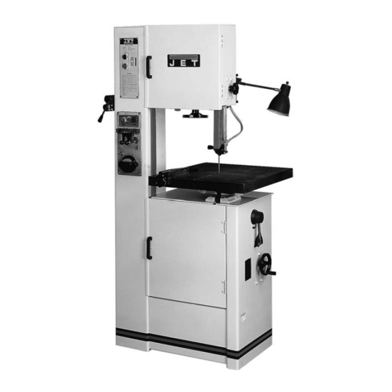
16-inch Metalworking Band Saw
Model VBS-1610
WALTER MEIER (Manufacturing) Inc.
427 New Sanford Road
LaVergne, Tennessee 37086
Part No. M-414485
Ph.: 800-274-6848
Revision H 10/2013
www.jettools.com
Copyright © 2013 Walter Meier (Manufacturing) Inc.
Advertisement
Table of Contents

Subscribe to Our Youtube Channel
Related Manuals for Jet VBS-1610


Summary of Contents for Jet VBS-1610
- Page 1 This .pdf document is bookmarked Operating Instructions and Parts Manual 16-inch Metalworking Band Saw Model VBS-1610 WALTER MEIER (Manufacturing) Inc. 427 New Sanford Road LaVergne, Tennessee 37086 Part No. M-414485 Ph.: 800-274-6848 Revision H 10/2013 www.jettools.com Copyright © 2013 Walter Meier (Manufacturing) Inc.
-
Page 2: Warranty And Service
JET, Wilton and Powermatic-branded websites are given as general information and are not binding. JET, Wilton and Powermatic reserve the right to effect at any time, without prior notice, those alterations to parts, fittings, and accessory equipment which they may deem necessary for any reason whatsoever. -
Page 3: Table Of Contents
18.0 Replacement Parts ............................. 21 18.1.1 VBS-1610 Band Saw – Exploded View ....................22 18.1.2 VBS-1610 Band Saw (Welder Assembly) – Exploded View ............... 23 18.1.3 VBS-1610 Band Saw – Parts List ......................24 19.0 Electrical diagram (VBS-1610) ........................28... -
Page 4: Safety Warnings
that are specifically designed to filter out microscopic particles. 10. Do not operate this machine while tired or under the influence of drugs, alcohol or any 3.0 Safety warnings medication. 11. Make certain the switch is in the OFF position 1. -
Page 5: About This Manual
This manual is provided by Walter Meier (Manufacturing) Inc. covering the safe operation and maintenance procedures for a JET Model VBS-1610 Band Saw. This manual contains instructions on installation, safety precautions, general operating procedures, maintenance instructions and parts breakdown. Your machine has been designed and constructed to provide years of trouble-free operation if used in accordance with the instructions as set forth in this document. -
Page 6: Specifications
5.0 Specifications Model number ............................VBS-1610 Stock number .............................. 414485 Blade speed ............................... variable Low range (SFM) ............................ 82-330 High range (SFM) ..........................985-3950 Capacities: Height (max. thickness) ..........................10” Throat (max. width) ..........................15-1/2” Welder capacity ............................5/8" Motor ............TEFC, 2HP(1.5kW), 3PH, 230/460V (prewired 230V), 6.2/3.1A, 60Hz Table size .............................. -
Page 7: Uncrating And Assembly
Failure to comply may cause serious injury. diesel oil. Do not use gasoline, paint thinner, or any cellulose-based product, as these will The VBS-1610 Band Saw is rated at 230/460V and damage painted surfaces. comes from the factory prewired 230V. -
Page 8: Controls
Anneal Button (K, Figure 3) – located on blade 9.0 Controls welder panel. Press and hold to anneal blade, release to stop. Low/High Range Shift Lever (B, Figure 2) – Pull Blade Clamp Pressure Knob (L, Figure 3) – toward front of machine to shift into low speed located on blade welder panel. -
Page 9: Adjustments
Table Tilt Mechanism – located under work table. 2. Apply finger pressure to blade. Travel from To tilt table left or right, loosen two socket head vertical should be approximately 3/8" each cap screws (P, Figure 5) at rear of mechanism. To way. -
Page 10: Top Guide Adjustment
Blade guide adjustment has been set by the 4. Remove blade from both wheels manufacturer. Should future adjustment maneuver it around blade guard on column needed, proceed as follows. and protective shield on upper blade guide. Use gloves when handling blades. 1. -
Page 11: Set Type
11.7 Blade breakage Skip Tooth - have better chip clearance (larger gullet) and are used on softer, non-ferrous Band saw blades are subject to high stresses and materials such as aluminum, copper, magnesium, breakage sometimes unavoidable. and soft brass. However, many factors can be controlled to help Hook Tooth - provides a chip breaker and has less prevent most blade breakage. -
Page 12: Removing Teeth
IMPORTANT: If a blade has been cut by using clamp. Then position the end of the blade snips, the ends of the blade must be ground midway between left and right clamps. Tighten square before welding them together, as shown in left clamp. -
Page 13: Annealing
excess weld material using the grinder. Refer to section 12.5, Blade grinding. If blade is thicker at the weld than at the rest of the blade, using the blade may damage the guides. The following are variations of the general procedure, based upon blade type: 12.4.1 Carbon steel blades 1. -
Page 14: Blade Grinding
The following Figure 17 illustrates some unacceptable grindings. procedure will be adequate, however, for break-in of JET-supplied blades on lower alloy ferrous materials. 1. Use a section of round stock. 2. Operate the saw at low speed. Start the cut with a very light feed rate. -
Page 15: Evaluating Cutting Efficiency
13.3 Evaluating cutting efficiency Use a brush to loosen accumulated chips and debris. Use a shop vacuum to remove the debris. The best way to determine whether a blade is Make sure the chip brush on the lower band wheel cutting efficiently is to observe the chips formed by is properly adjusted. -
Page 16: Troubleshooting
15.0 Troubleshooting 15.1 Operating problems Table 1 Trouble Probable Cause Remedy Blade has been improperly welded. Re-weld blade. See section 12.3 Blade not installed properly. Set guide inserts closer, and increase blade tension. Saw blade is twisted. Feeding workpiece too forcefully. Decrease feed rate. -
Page 17: Mechanical And Electrical Problems
15.2 Mechanical and electrical problems Table 2 Trouble Probable Cause Remedy Machine will not Verify machine is connected to power start/restart or source. Make sure START button is No incoming power. repeatedly trips circuit pushed in completely, and STOP button breaker or blows is disengaged. -
Page 18: Welded Blade Inspection
15.3 Welded blade inspection Table 3 Trouble Probable Cause Remedy Weld is misaligned. Dirt or scale on clamp jaws or blade. Always keep jaws clean. Clean blade before welding. Blade ends not square. Before welding, grind cut edges of blade until they are square. Use the shear on the band saw for square cuts. -
Page 19: Welder Mechanical Problems
15.4 Welder mechanical problems Table 4 Trouble Probable Cause Remedy Wire connection is poor; connecting Change switch, or grind the connecting point of welding switch is bad. port with a file. Weld could not be Transformer burned out. Change transformer, or rewire it. made. -
Page 20: Speed And Pitch Chart
16.0 Speed and pitch chart Table 5... -
Page 21: Typical Band Saw Operations
17.0 Typical Band Saw Operations Figure 18 18.0 Replacement Parts Replacement parts are listed on the following pages. To order parts or reach our service department, call 1- 800-274-6848 Monday through Friday (see our website for business hours, www.jetttools.com). Having the Model Number and Serial Number of your machine available when you call will allow us to serve you quickly and accurately. -
Page 22: Vbs-1610 Band Saw - Exploded View
18.1.1 VBS-1610 Band Saw – Exploded View... -
Page 23: Vbs-1610 Band Saw (Welder Assembly) - Exploded View
18.1.2 VBS-1610 Band Saw (Welder Assembly) – Exploded View... -
Page 24: Vbs-1610 Band Saw - Parts List
18.1.3 VBS-1610 Band Saw – Parts List Index No Part No Description Size ....VBS1610-GB..... Gear Box Assembly Complete............... 1 0500 ..0500 ......Gear Box * ....................1 0510 ..0510 ......Gear Box Cover * ..................1 0520 .. - Page 25 Index No Part No Description Size 2020 ..2020 ......Motor Suspension Arm .................. 2 2030 ..2030 ......Motor Spring Housing ..................1 2040 ..2040 ......Motor Spring ....................1 2050 ..2050 ......Motor Spring Support..................1 3010 ..
- Page 26 Index No Part No Description Size 6160 ..6160 ......Micro Switch ....................1 6170 ..VBS16-617 ....Pressure Adjust Switch .................. 1 6180 ..VBS16-618 ....Shaft ......................1 6200 ..VBS16-620 ....Cam ....................... 1 6210 ..
- Page 27 G6205 ..BB-6205 ....Ball Bearing ....................2 G6303 ..BB-6303 ....Ball Bearing ....................1 G6306 ..BB-6303 ....Ball Bearing ....................1 G6304 ..BB-6304 ....Ball Bearing ....................1 ....STRIPE-1-3/4 .... JET Stripe (not shown) ..........1-3/4”...... per ft.
-
Page 28: Electrical Diagram (Vbs-1610)
19.0 Electrical diagram (VBS-1610)
Need help?
Do you have a question about the VBS-1610 and is the answer not in the manual?
Questions and answers