CMA Dishmachines L-1X Owner's Manual
Hide thumbs
Also See for L-1X:
- Parts manual (19 pages) ,
- Owner's manual (19 pages) ,
- Specifications (2 pages)
Table of Contents
Advertisement
Advertisement
Table of Contents

Subscribe to Our Youtube Channel
Related Manuals for CMA Dishmachines L-1X


Summary of Contents for CMA Dishmachines L-1X
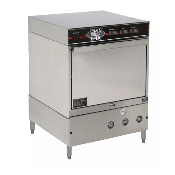
- Page 1 Owner’s Manual Keep with machine for reference MODEL L-1X & L-1X16 Installation & Operations Rev 1.15 C M A D I S H M A C H I N E S 1 2 7 0 0 K N O T T A V E N U E...
-
Page 2: Table Of Contents
ABLE OF ONTENTS CMA-L-1X & L-1X16 ODEL 1. SPECIFICATIONS ..................2 1.1. L-1X & L-1X16..........................2 1.2. L-1X L-1X16 O ..................3 PERATIONAL YCLE 2. GETTING STARTED ..................5 2.1. L-1X L-1X16 ..................5 NTRODUCTION TO THE 2.2....................... 6 ECEIVING AND NSTALLATION 2.2.1. -
Page 3: Specifications
13.4 AMPS *MUST CONNECT TO DEDICATED 20 AMP SUPPLY CIRCUIT. COMPLIANCE WITH LOCAL ELECTRICAL CODES MUST BE FOLLOWED. SHIPPING WEIGHT L-1X (Approximate) 190# 86.2 kg L-1X16 (Approximate) 195# 88.5 kg Page MODEL L-1X & L-1X16 INSTALLATION & OPERATION MANUAL Rev. 1.15... -
Page 4: L-1X And L-1X16 Operational Cycle
1.2. L-1X and L-1X16 Operational Cycle The L-1X and L-1X16 Operational Cycle has a total cycle time of 2 minutes (120 seconds). The Timing Diagram and the steps listed below detail the individual functions that are executed during each Operational Cycle. - Page 5 7. Cam switch 8 operates the optional sustainer heater. This cam assures that the sustainer heater only turns on when the dishmachine is not in a cycle. This prevents the machine from drawing too much electrical current at any one time. Page MODEL L-1X & L-1X16 INSTALLATION & OPERATION MANUAL Rev. 1.15...
-
Page 6: Getting Started
The supply water to the L-1X and L-1X16 must be a minimum of 140°F. The pipe supplying the water must be ½” minimum. The plumbing connection is located at the back of the machine. The drain is a 1"... -
Page 7: Receiving And Installation
2.2.1. Electrical A 20-amp, 115 volt, 60 Hz dedicated circuit must be used to supply electrical power to the L-1X or L-1X16 Dishmachine (see specification sheet page 1). The power connection must be such that there is sufficient length of flexible conduit or power cord to permit the machine to be moved for cleaning. -
Page 8: Installers Checklist
Drain hose is installed with adequate air gap Dishmachine is properly grounded Dishmachine is properly leveled Machine circuit breaker is labeled “DISHWASHER” Machine has been connected with correctly sized wire (12 gauge minimum) Page MODEL L-1X & L-1X16 Installation & Operations Manual Rev. 1.15... -
Page 9: Operation
It is essential that the operator thoroughly understand the importance of pre-scrapping the dishes before loading them. The L-1X and L-1X16 are equipped with a removable drain screen. The drain screen can be easily removed for cleaning between Operational Cycles of the dishmachine. -
Page 10: Proper Filling
Cam 4 can be adjusted to increase the amount of water that is automatically fed into the machine during a cycle (see section 4.1.1 Cam Adjustment). Page MODEL L-1X & L-1X16 Installation & Operations Manual Rev. 1.15... -
Page 11: Maintenance
5. Adjust the trailing edge of the cam groove by rotating the appropriate side of the cam in the proper direction to either increase or decrease the cam’s groove; resulting in increasing or decreasing the total time that switch will be held ON. Page MODEL L-1X & L-1X16 PARTS MANUAL Rev. 1.15... -
Page 12: Quick Service Guide
Replace solenoid coil, P/N 00738.10 Delimer switch in wrong position Switch to NORMAL position Sanitizer pump does not run Faulty 5th micro switch Replace switch, P/N 00411.00 Faulty sanitizer pump motor Replace motor, P/N 00416.00 Page MODEL L-1X & L-1X16 PARTS MANUAL Rev. 1.15... -
Page 13: Troubleshooting
Replace heater relay P/N: 00631.00 *The timer assembly motor ( ) or micro switches ( ) can be replaced P/N: 00501.00 P/N: 00411.00 independently if that is the only component that has failed. Page MODEL L-1X & L-1X16 PARTS MANUAL Rev. 1.15... -
Page 14: Electrical Diagram
P/N: 00408.80 (Cam 5) *The timer assembly motor ( ) or micro switches ( ) can be replaced P/N: 00501.00 P/N: 00411.00 independently if that is the only component that has failed. Page MODEL L-1X & L-1X16 PARTS MANUAL Rev. 1.15... - Page 15 Replace pump motor P/N: 00201.00 *The timer assembly motor ( ) or micro switches ( ) can be replaced P/N: 00501.00 P/N: 00411.00 independently if that is the only component that has failed. Page MODEL L-1X & L-1X16 PARTS MANUAL Rev. 1.15...
-
Page 16: Addendum For Machines Installed In The City Of Chicago
1. All low energy models must have low level sani-alarms, both visual and audio. 2. All models must have a City of Chicago approval data label affixed to the machine. 3. Chlorine sanitizer must be a minimum of 100 PPM. Page MODEL L-1X & L-1X16 PARTS MANUAL Rev. 1.15... -
Page 17: Appendix A: Operator & Cleaning Instructions
Appendix A: Operator & Cleaning Instructions MODEL L-1X & L-1X16 PARTS MANUAL Rev. 1.15 Page... -
Page 18: Electrical Diagram (Effective 06/2007)
Electrical Diagram 6. Electrical Diagram (Effective 06/2007) Page MODEL L-1X & L-1X16 PARTS MANUAL Rev. 1.15... -
Page 19: Electrical Diagram (Old Model)
Electrical Diagram 7. Electrical Diagram (Old Model) Page MODEL L-1X & L-1X16 PARTS MANUAL Rev. 1.15...
Need help?
Do you have a question about the L-1X and is the answer not in the manual?
Questions and answers