Table of Contents
Advertisement
Quick Links
Download this manual
See also:
User Manual
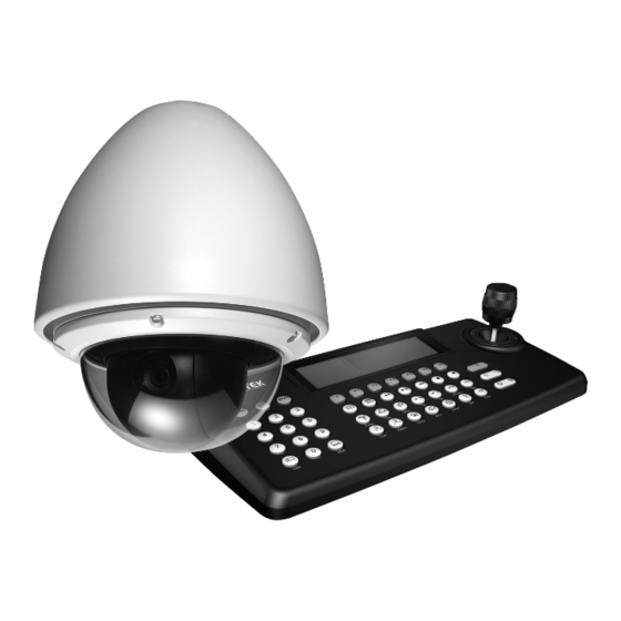
VT-PTZ10
Ultra-Compact PTZ Camera
with 10x Optical Zoom
• Built-In 3.8-38mm Lens with 10x Optical / 10x Digital Zoom.
• High Performance 1/4" CCD with 500 TV Lines.
• True Day/Night function with ICR.
• 128 Presets programmed with view direction, zoom, and BLC.
• 4 Patterns record and play back user preference of surveillance path up to 120º sec.
• 8 Scans: 8 speed steps from slow to medium panning with smooth Diagonal Scan.
• 4 Tours: Each tour consists up to 32 Presets, Patterns, and/or Scans.
• 4 Alarm inputs with 1~4 priority / 1 Auxiliary output with programmable NC & NO.
• 8 Privacy Zones: Video off or up to 8 masked blocks
• 64 steps of variable speed from 0.4?/sec to 90?/sec. Max manual speed 190?/sec with
Turbo key pressed, Preset speed is 380?/sec.
• Built-in RS-485 receiver driver.
• Built-in power-line surge protection and lightning protection.
• Optional Wall Mount, Indoor/Outdoor pendant housing, and Heater & Blower Kit
Advertisement
Table of Contents

Related Manuals for Vitek VT-PTZ10


Summary of Contents for Vitek VT-PTZ10
- Page 1 VT-PTZ10 Ultra-Compact PTZ Camera with 10x Optical Zoom • Built-In 3.8-38mm Lens with 10x Optical / 10x Digital Zoom. • High Performance 1/4” CCD with 500 TV Lines. • True Day/Night function with ICR. • 128 Presets programmed with view direction, zoom, and BLC.
- Page 2 Before installing the Dome camera, please make sure that the following items are included in the box: 1. Mini Speed Dome Camera 2. Instruction Manual 3. Mounting Hardware If any of these materials are missing, please contact the vendor or VITEK customer help desk immediately.
-
Page 3: Disclaimer
VITEK. VITEK makes no warranties for damages resulting from corrupted or lost data due to a mistaken operation or malfunction of the Speed Dome Cameras, peripheral... -
Page 4: Warning And Caution
VT-PTZ10 WARNING AND CAUTION WARNING TO REDUCE THE RISK OF FIRE OR ELECTRIC SHOCK, DO NOT EXPOSE THIS PRODUCT TO RAIN OR MOISTURE. DO NOT INSERT ANY METALLIC OBJECTS THROUGH THE VENTILATION GRILLS OR OTHER OPENINGS ON THE EQUIPMENT. CAUTION... -
Page 5: Fcc Compliance Statement
VT-PTZ10 FCC COMPLIANCE STATEMENT FCC INFORMATION: THIS EQUIPMENT HAS BEEN TESTED AND FOUND TO COMPLY WITH THE LIMITS FOR A CLASS A DIGITAL DEVICE, PURSUANT TO PART 15 OF THE FCC RULES. THESE LIMITS ARE DESIGNED TO PROVIDE REASONABLE PROTECTION AGAINST HARMFUL INTERFERENCE WHEN THE EQUIPMENT IS OPERATED IN A COMMERCIAL ENVIRONMENT. -
Page 6: Important Safeguards
VT-PTZ10 IMPORTANT SAFEGUARDS 1. Read these instructions. 2. Heed all warnings. 3. Follow all instructions. 4. Do not use this equipment near water. 5. Clean only with dry cloth. 6. Do not block any ventilation openings. Install in accordance with the manufacturer's instructions. -
Page 7: Table Of Contents
VT-PTZ10 TABLE OF CONTENTS DISCLAIMER ........................2 WARNING AND CAUTION ..................... 3 FCC COMPLIANCE STATEMENT ................. 4 CE COMPLIANCE STATEMENT ................... 4 IMPORTANT SAFEGUARDS ..................5 I. INTRODUCTION ......................8 Features ..............................8 II. INSTALLATION AND CONFIGURATION ..............9 2.1 Typical System Configuration ......................9 2.2 Basic Configuration of Speed Dome Camera System .............. - Page 8 VT-PTZ10 3.4.7 NIGHT SHOT MENU ( MENU => CAMERA =>NIGHT SHOT) ..................36 3.4.8 CAMERA INITIALIZE ( MENU => CAMERA =>CAMERA INITIALIZE) ................36 3.5 SETUP ( MENU => SETUP) ......................37 3.5.1 FLIP (MENU => SETUP => FLIP) ..........................37 3.5.2 SPEED (MENU =>...
-
Page 9: Introduction
VT-PTZ10 I. INTRODUCTION Features The Speed Dome Camera features a high resolution 1/4‖ Interline Transfer CCD imager for enhanced lowlight sensitivity. User friendly, on-screen pull-down menus and short- cuts make it easy to setup and program functions. System information aides trouble shooting by displaying the hardware and software version of the camera’s firmware version, baud rate, and protocol. -
Page 10: Installation And Configuration
VT-PTZ10 II. INSTALLATION AND CONFIGURATION 2.1 Typical System Configuration Additional Speed Dome joystick controllers and a variety of external switching devices such as multiplexers (MUXes) and Digital Video Recorders (DVRs) may be incorporated to accommodate the needs from a small to a large surveillance/security system. -
Page 11: Basic Configuration Of Speed Dome Camera System
VT-PTZ10 2.2 Basic Configuration of Speed Dome Camera System POWER AC 24V STP AWG # 22 BNC MONITOR 4 ALARM INPUT 1 AUX OUTPUT RS-485 HALF DUPLEX MODE CONTROLLER DOME Figure 2 - Basic Installation Diagram... -
Page 12: Connecting The Speed Dome Directly Into The Dvr
VT-PTZ10 2.3 Connecting the Speed Dome directly into the DVR Locate the RS485 + & - conductor wire from the Speed Dome Camera. Connect the + & - into the TRX+ & TRX- ports of the DVR. Tx+ & Tx- ports can be found in the rear part of the DVR. -
Page 13: Connecting Both Speed Dome And Dvr Via J-Box
VT-PTZ10 2.5 Connecting Both Speed Dome and DVR via J-box Figure 5 - Connecting Camera & DVR into Controller... - Page 14 VT-PTZ10 The dome camera must be installed by qualified service personnel. Before installing the dome camera system, this instruction manual must be read thoroughly and understood fully. Dome cameras must be set up properly before starting the installation. This involves properly setting configuration switches. Figure 6 shows the location of these switches.
-
Page 15: Principle Of Termination
VT-PTZ10 2.6 Principle of Termination Every device that is connected at the end of the communication data line must be terminated by either the DIP switch setting or an appropriate device such as a termination jumper to prevent potential control signal errors. - Page 16 VT-PTZ10 S1:Dome1 port Termination ON DVR Termination ON SW1:Termination ON SW1:Termination ON S1:Dome1 port Termination ON DVR Termination ON SW1:Termination ON SW1:Termination ON SW1:Termination ON SW1:Termination ON S1:Dome1 port Termination ON S4:DVR port Termination ON DVR Termination ON DVR Termination ON...
-
Page 17: Dome Camera Address (Id)
VT-PTZ10 2.7 Dome Camera Address (ID) Each dome camera must have a unique address (ID). Identical IDs on the same line may damage the control circuit caused by an electrical short. When installing multiple dome cameras or a DVR, it is recommended that the dome camera ID’s be identical to the camera port of the DVR. -
Page 18: Connections
VT-PTZ10 2.9 Connections • How to Connect RS485 The dome camera has a built-in RS-485 receiver so that it can be controlled remotely by an external control device such as a joystick controller or a DVR. RS-485: Connect the TXA (Tx+) and TXB (Tx-) of the RS485 control devices (KBD, DVR…) to TRX+, TRX- of the dome camera. -
Page 19: Mounting The Dome Camera
VT-PTZ10 3.0 Mounting the Dome Camera Once all DIP switches are set properly and all external connections are made, the dome camera can be mounted. The Mini PTZ Dome camera is designed to mount on a structural body supporting loads up to 3 Kg. See Figure 11. -
Page 20: Power On And Boot-Up Sequence
VT-PTZ10 3.1 Power on and Boot-up Sequence When the power is applied to the dome camera, it will start the boot-up sequence. When boot-up is done, the following information is displayed on the monitor screen. RAM TEST CHECK NO. : OK! -
Page 21: Program & Operation
VT-PTZ10 III. PROGRAM & OPERATION Dome Camera Selection Prior to starting programming or operating a dome camera, please make sure that both the camera and the joystick controller are communicating. In order for changes to take effect for a camera, particular camera’s ID must be selected on the controller. -
Page 22: Functions
VT-PTZ10 3.1 FUNCTIONS By pressing the MENU button on the keyboard controller, the following On-screen MAIN MENU will be shown on the monitor screen. MAIN MENU FUNCTION ALARM SCREEN CAMERA SETUP EXIT Select the FUNCTIONS and then move the joystick to the right to access FUNCTIONS menu. -
Page 23: Preset (Menu => Functions => Preset Short Cut:prst )
VT-PTZ10 The HOME function applies to the predefined functions such as Preset, Tour, Pattern, or Scan function after the keyboard controller has been idle for a programmed time. Follow the steps below to program the Home function: 1. Select the camera number by pressing No. and CAM 2. - Page 24 VT-PTZ10 PRESET 01/8 NO. F I B TITLE 001 A A F xxxxxxxxxxxxxxxx 002 M M O ---------------- 003 - - - ---------------- 004 - - - ---------------- 005 - - - ---------------- 006 - - - ---------------- 007 - - -...
-
Page 25: Pattern (Menu => Functions => Patterns Or Shortcut: Ptrn)
VT-PTZ10 SHORTCUT TO PROGRAMMING PRESETS. Select direction of the camera, zoom and focus to be programmed, then press No. (1~64), and then press SHFT, PRST subsequently. The current view will be stored to the selected preset number if position is empty. If selected preset number is not empty, ―PRESET EXISTING‖... -
Page 26: Scan ( Menu => Functions => Scan Or Shortcut: Scan)
VT-PTZ10 5. Scroll down to the Save and Exit option and move the Joystick to the right to save and exit. 6. Naming the Pattern can be done by twisting the Joystick. Rotate the handle clockwise or counterclockwise to scroll through the alphanumeric characters, move the handle to right or left to select next or previous space. - Page 27 VT-PTZ10 Follow the steps below to program Scans. 1. Press the SCAN key to enter Auto Scan menu directly. (Or MENU => FUNCTIONS => SCAN). 2. Select an Auto Scan number by moving the Joystick left or right. 3. Twist the Joystick to enter the title by scrolling through the alphanumeric characters and move the handle to the right or left to move to the next space.
-
Page 28: Tour (Or Menu => Functions => Tour, Short Cut: Tour)
VT-PTZ10 3.1.5 TOUR (or MENU => FUNCTIONS => TOUR, Short Cut: TOUR) There are 4 programmable Tours. Each Tour consists of up to 8 Preset positions, Patterns, Scans or other Tours. Using second-level Tours, it can be expanded up to 56 functions in a single Tour. - Page 29 VT-PTZ10 Follow the steps below to program the Tours: 1. Press MENU => FUNCTIONS => TOUR, Short Cut: TOUR MENU to display the main menu on the monitor. No. + SHFT+TOUR will open directly Tour No. 2. Choose an empty location of function by moving the Joystick up or down.
-
Page 30: Alarm ( Menu => Alarm)
VT-PTZ10 3.2 ALARM ( MENU => ALARM) MAIN MENU FUNCTIONS ALARM SCREEN CAMERA SETUP EXIT Highlight ALARM in the main menu and move the joystick to the right to access ALARM setup. ALARM SETUP NO FUNC PRI OUT HLD LATCH... -
Page 31: Screen
VT-PTZ10 1. Press Menu to display the main menu on the monitor. Select the Alarm option by moving the Joystick up/down and then move to the right to enter the detail menu. 2. Select the alarm input number by moving the Joystick up or down and select the column to setup. -
Page 32: Language ( Menu => Screen => Language)
VT-PTZ10 3.3.1 LANGUAGE ( MENU => SCREEN => LANGUAGE) Moving the joystick handle to the right to select LANGUAGE options. Preferred language will be scrolled by moving the joystick to the right on LANGUAGE ENGLISH. 3.3.2 PRIVACY ZONE ( MENU => SCREEN => PRIVACY ZONE) Highlight PRIVACY ZONE and then move the joystick to the right to enter the menu. -
Page 33: North Direction ( Menu => Screen => North Direction)
VT-PTZ10 4. To adjust the ―marked‖ (privacy) area, press and hold down the SHFT/PGM key and then use the Joystick (direction and zoom) until getting desired view. Release the key, the right column will be set to ON. (Or twist the zoom handle or hit the zoom button to start PTZ control for view selection and hit the Focus button to exit from control mode.) -
Page 34: Camera Title ( Menu => Screen => Camera Title)
VT-PTZ10 2. Select the zone number by moving the Joystick up or down. Select Start, End or number column to be set by moving the handle to the right or left. The selected column will be highlighted. 3. Twist the joystick handle on the No. column to enter zone title. Select alphanumeric characters by rotating the handle. -
Page 35: Camera ( Menu => Camera)
VT-PTZ10 NORTH DIRECTION : turn on or off the azimuth direction display. DOME POSITION : turn on or off the coordinates display. DOME ID : turn on or off the dome ID display. ZOOM MAGNIFICATION : turn on or off the current zoom magnification level display. -
Page 36: Ae Control ( Menu => Camera => Exposure Setup)
VT-PTZ10 WB SETUP MODE OUTDOOR R GAIN : B GAIN : EXIT MODE MANUAL / OUTDOOR / INDOOR / AWC R GAIN 0 ~ 100 B GAIN 0 ~ 100 Use the AWC mode for normal use. RGAIN / BGAIN modes are controllable only in MANUAL Mode Moving the Joystick to the right or left to change. -
Page 37: Back Light Compensation ( Menu Camera Back Light)
VT-PTZ10 3.4.4 BACK LIGHT COMPENSATION ( MENU CAMERA Back Light) Objects in front of bright backgrounds will be clearer with BLC ON. LOW / MID. / HIGH / OFF 3.4.5 SHARPENSS CONTROL ( MENU => CAMERA =>SHAPENESS) Higher the value, outlines of the image will be enhanced (0~31) 3.4.6 DIGITAL ZOOM ( MENU =>... -
Page 38: Setup ( Menu => Setup)
VT-PTZ10 CAMERA INITIALIZE ARE YOU SURE : (Y/N) YES : ENTER OR MENUKEY : ESC KEY 3.5 SETUP ( MENU => SETUP) CONFIGURATION MENU FLIP FUNTION : ON P/T SPEED : FAST PRESET FREEZE : OFF PANNING RANGE TILT LIMIT... -
Page 39: Tilt Limit (Menu => Setup => Tilt Limit)
VT-PTZ10 PAN RANGE SETUP RIGHT LIMITE : 000.0 LEFT LIMT : 007.2 ENABLE : ON / OFF SWAP RIGHT LEFT SAVE AND EXIT When the dome camera is installed near a wall or on a corner, panning range can be limited by user. -
Page 40: Line Lock Control (Menu = Setup => Line Lock Control)
VT-PTZ10 3.5.7 LINE LOCK CONTROL (MENU = SETUP => LINE LOCK CONTROL) LINE LOCK SETUP MODE INTERNAL PHASE (0~359) EXIT MODE INTERNAL / EXTERNAL Adjusts phase of picture with other PHASE 0~359 cameras in EXTERNAL mode. EXIT (ESC TO EXIT) 3.5.8 FACTORY DEFAULT (MENU =>... -
Page 41: System Information (Menu => Setup => System Information)
VT-PTZ10 3.5.10 SYSTEM INFORMATION (MENU => SETUP => SYSTEM INFORMATION) SYSTEM INFORMATION CAMERA TYPE : XXXXXXX H/W VERSION : V1.00 ROM VERSION : V1.00 PROTOCOL : EZ BUADRATE : 9600BPS EXIT MENU This screen shows information of the dome camera for service or trouble shooting APPENDIX A —... - Page 42 VT-PTZ10 Alarm Output 1 Normal relays 24 VDC/1A Max (selectable NC/NO) Alarm Input 4 Normal dry contact (selectable NC/NO) Control RS-485 baud rate:2400~38400bps (default:9600bps) Access Time 0.75 second maximum preset recall time ID (Camera Address) Physical 99, Logical 3999 Mechanical...
- Page 43 VT-PTZ10 Figure 10-Dimension...
-
Page 44: Appendix B - Troubleshooting
VT-PTZ10 Appendix B — Troubleshooting If problems occur, verify the installation of the camera with the instructions in this manual. Isolate the problem from the equipments in the system and refer to the equipment manual for further information. Problem Solution Verify that power is connected to all components in the system. -
Page 45: Glossary
VT-PTZ10 Glossary ALARM ACTIONS The assigned responses of the dome camera when there is input status change. The dome may call Presets for each of the eight inputs. The dome reports the alarm states to the Keyboard controller for processing. - Page 46 VT-PTZ10 INPUT DEVICES External devices that provide information about the condition of system components that connect to the inputs on the dome camera. Typical input devices include door contacts, motion detectors and smoke detectors. IR MODE A feature of the camera that permits manual or automatic switching between color and IR (black-and-white) operation.
- Page 47 VT-PTZ10 WHITE BALANCE Adjustments in the color hue (red and blue) gains for a camera so that true white appears white in the image. It is normally compensated for by the automatic gain control. In some lighting conditions, you may need to manually adjust the red and blue settings for optimal viewing.
- Page 51 (3) years, or as otherwise stated above, from the date of purchase by the end user. This warranty is non-transferable and extends only to the original buyer or end user customer of a VITEK Authorized Reseller.
- Page 52 28492 CONSTELLATION ROAD VALENCIA, CA 91355 WWW.VITEKCCTV.COM | 888-VITEK-70...
Need help?
Do you have a question about the VT-PTZ10 and is the answer not in the manual?
Questions and answers