Table of Contents
Advertisement
Quick Links
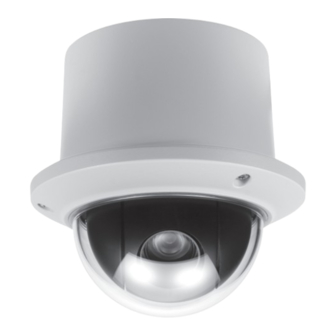
VT-PTZ12WH
Ultra Compact 960H PTZ Camera
with 12X Optical Zoom and WDR
• 1/4" Sony Super HAD II CCD with 700 TV Lines (960H)
• Built-In 3.8mm to 45.6mm Lens with 12x Optical / 32x Digital Zoom
• True Day/Night function with ICR
• 128 Presets programmed with view direction, zoom, and BLC
• 4 Patterns record and play back user preference of surveillance path up to 120º sec.
• 8 Scans: 8 speed steps from slow to medium panning with smooth Diagonal Scan
• 4 Tours: Each tour consists up to 32 Presets, Patterns, and/or Scans
• Fully Gasket Sealed IP-66 Rated Weatherproof Design
• 4 Alarm inputs with 1~4 priority / 1 Auxiliary output with programmable NC & NO
• 8 Privacy Zones: Video off or up to 8 masked blocks
• 64 steps of variable speed from 0.4º/sec to 90º/sec. Max manual speed 190º/sec
with Turbo key pressed, Preset speed is 380º/sec.
• Built-in RS-485 receiver driver.
• Built-in power-line surge protection and lightning protection
• Built-in Heater/Blower for use in Extreme Temperatures
Advertisement
Table of Contents

Related Manuals for Vitek VT-PTZ12WH


Summary of Contents for Vitek VT-PTZ12WH
- Page 1 VT-PTZ12WH Ultra Compact 960H PTZ Camera with 12X Optical Zoom and WDR • 1/4” Sony Super HAD II CCD with 700 TV Lines (960H) • Built-In 3.8mm to 45.6mm Lens with 12x Optical / 32x Digital Zoom • True Day/Night function with ICR •...
- Page 2 Before installing the Dome camera, please make sure that the following items are included in the box: 1. Mini Speed Dome Camera 2. Instruction Manual 3. Mounting Hardware If any of these materials are missing, please contact the vendor or VITEK customer help desk immediately.
-
Page 3: Disclaimer
VITEK. • VITEK makes no warranties for damages resulting from corrupted or lost data due to a mistaken operation or malfunction of the Speed Dome Cameras, peripheral... -
Page 4: Warning And Caution
VT-PTZ12WH WARNING AND CAUTION... -
Page 5: Fcc Compliance Statement
VT-PTZ12WH FCC COMPLIANCE STATEMENT FCC INFORMATION: THIS EQUIPMENT HAS BEEN TESTED AND FOUND TO COMPLY WITH THE LIMITS FOR A CLASS A DIGITAL DEVICE, PURSUANT TO PART 15 OF THE FCC RULES. THESE LIMITS ARE DESIGNED TO PROVIDE REASONABLE PROTECTION AGAINST HARMFUL INTERFERENCE WHEN THE EQUIPMENT IS OPERATED IN A COMMERCIAL ENVIRONMENT. -
Page 6: Important Safeguards
VT-PTZ12WH IMPORTANT SAFEGUARDS 1. Read these instructions. 2. Heed all warnings. 3. Follow all instructions. 4. Do not use this equipment near water. 5. Clean only with dry cloth. 6. Do not block any ventilation openings. Install in accordance with the manufacturer's instructions. -
Page 7: Table Of Contents
VT-PTZ12WH TABLE OF CONTENTS DISCLAIMER ........................2 I. INTRODUCTION ......................7 Features ..............................7 II. INSTALLATION AND CONFIGURATION ..............8 2.1 Typical System Configuration ......................8 2.2 Basic Configuration of Speed Dome Camera System ..............9 ... -
Page 8: Introduction
VT-PTZ12WH I. INTRODUCTION Features The Speed Dome Camera features a high resolution 1/4” Interline Transfer CCD imager for enhanced lowlight sensitivity. User friendly, on-screen pull-down menus and short- cuts make it easy to setup and program functions. System information aides trouble shooting by displaying the hardware and software version of the camera’s firmware version, baud rate, and protocol. -
Page 9: Installation And Configuration
VT-PTZ12WH II. INSTALLATION AND CONFIGURATION 2.1 Typical System Configuration Additional Speed Dome joystick controllers and a variety of external switching devices such as multiplexers (MUXes) and Digital Video Recorders (DVRs) may be incorporated to accommodate the needs from a small to a large surveillance/security system. -
Page 10: Basic Configuration Of Speed Dome Camera System
VT-PTZ12WH 2.2 Basic Configuration of Speed Dome Camera System POWER AC 24V STP AWG # 22 BNC MONITOR 4 ALARM INPUT 1 AUX OUTPUT RS-485 HALF DUPLEX MODE CONTROLLER DOME Figure 2 - Basic Installation Diagram... -
Page 11: Connecting The Speed Dome Directly Into The Dvr
VT-PTZ12WH 2.3 Connecting the Speed Dome directly into the DVR Locate the RS485 + & - conductor wire from the Speed Dome Camera. • Connect the + & - into the TRX+ & TRX- ports of the DVR. Tx+ & Tx- ports can be •... - Page 12 VT-PTZ12WH 2.5 Connecting Both Speed Dome and DVR via J-box Figure 5 - Connecting Camera & DVR into Controller...
- Page 13 VT-PTZ12WH The dome camera must be installed by qualified service personnel. Before installing the dome camera system, this instruction manual must be read thoroughly and understood fully. Dome cameras must be set up properly before starting the installation. This involves properly setting configuration switches. Figure 6 shows the location of these switches.
-
Page 14: Principle Of Termination
VT-PTZ12WH 2.6 Principle of Termination There are two general types of wiring scheme for PTZ cameras: • Daisy-Chain Wiring • Home-Run Wiring Each scheme has a different termination method Daisy-Chain Wiring Every device that is connected at the end of the communication data line (daisy-chain) must be terminated by either the DIP switch setting or an appropriate device such as a termination jumper to prevent potential control signal errors. - Page 15 VT-PTZ12WH...
-
Page 16: Dome Camera Address (Id)
VT-PTZ12WH S1:Dome1 port Termination ON DVR Termination ON SW1:Termination ON SW1:Termination ON S1:Dome1 port Termination ON DVR Termination ON SW1:Termination ON SW1:Termination ON SW1:Termination ON SW1:Termination ON S1:Dome1 port Termination ON S4:DVR port Termination ON DVR Termination ON DVR Termination ON... -
Page 17: Setting Protocols
VT-PTZ12WH Cam Port 1 = Dome ID1, Cam Port 2 = Dome ID 2 … Cam Port 16 = Dome ID 16. If more than 16 dome cameras are installed using two or more DVRs the following formula is useful to determine the Dome ID: ID =16x (n-1) +m (where n= number of DVR, m=Camera Port) Refer to Figures 9 for setting the dome camera address (ID) and protocol selection. -
Page 18: Connections
VT-PTZ12WH 2.9 Connections • How to Connect RS485 The dome camera has a built-in RS-485 receiver so that it can be controlled remotely by an external control device such as a joystick controller or a DVR. RS-485: Connect the TXA (Tx+) and TXB (Tx-) of the RS485 control devices (KBD, DVR…) to TRX+, TRX- of the dome camera. -
Page 19: Mounting The Dome Camera
VT-PTZ12WH 3.0 Mounting the Dome Camera Once all DIP switches are set properly and all external connections are made, the dome camera can be mounted. The Mini PTZ Dome camera is designed to mount on a structural body supporting loads up to 3 Kg. See Figure 11. -
Page 20: Power On And Boot-Up Sequence
VT-PTZ12WH 3.1 Power on and Boot-up Sequence When the power is applied to the dome camera, it will start the boot-up sequence. When boot-up is done, the following information is displayed on the monitor screen. RAM TEST CHECK NO. : OK! -
Page 21: Program & Operation
VT-PTZ12WH III. PROGRAM & OPERATION Dome Camera Selection Prior to start programming or operating a dome camera, please make sure that both the camera and the joystick controller are communicating. In order for changes to take effect for a camera, particular camera’s ID must be selected on the controller. -
Page 22: Home Function (Menu =>Functions => Home Function)
VT-PTZ12WH Select the FUNCTIONS and then move the joystick to the right to access FUNCTIONS menu. FUNCTIONS HOME FUNCTION PRESET PATTERN SCAN TOUR EXIT 3.1.1 HOME FUNCTION (MENU =>FUNCTIONS => HOME FUNCTION) After HOME FUNCTION item has been selected, follow the directions below to set HOME function. -
Page 23: Preset (Menu => Functions => Preset Short Cut:prst )
VT-PTZ12WH 6. Select Function Number by pulling the Joystick down, and twist the Joystick to the CCW/CW (or turn right/left). The executable function number will be scrolled. If selected function is not programmed, it won’t change. Go to setup function first. - Page 24 VT-PTZ12WH PRESET 01/8 NO. F I B TITLE 001 A A F xxxxxxxxxxxxxxxx 002 M M O ---------------- 003 - - - ---------------- 004 - - - ---------------- 005 - - - ---------------- 006 - - - ---------------- 007 - - -...
-
Page 25: Pattern (Menu => Functions => Patterns Or Shortcut: Ptrn)
VT-PTZ12WH NOTE: Press the Home or OFF button at programmed position to delete the preset. SHORTCUT TO PROGRAMMING PRESETS. Select direction of the camera, zoom and focus to be programmed, then press No. (1~64 ), and then press SHFT , PRST subsequently. The current view will be stored to the selected preset number if position is empty. -
Page 26: Scan ( Menu => Functions => Scan Or Shortcut: Scan)
VT-PTZ12WH 5. Move to the title field to edit/enter the name. Rotate the handle CW and CCW to scroll through the alphanumeric characters. Moving the handle to right or left to select next or previous digit. 6. To finish entering the title, move the Joystick up/down. - Page 27 VT-PTZ12WH Follow the steps below to program Scans. 1. Press the SCAN key to enter Auto Scan menu directly. (Or MENU => FUNCTIONS => SCAN). 2. Select an Auto Scan number by moving the Joystick left or right. 3. Highlight the title and twist the Joystick to edit the title by scrolling through the alphanumeric characters and move the handle to the right or left to move to the next space.
- Page 28 VT-PTZ12WH 3.1.5 TOUR (or MENU => FUNCTIONS => TOUR, Short Cut: TOUR) There are 4 programmable Tours. Each Tour consists of up to 8 Preset positions, Patterns, Scans or other Tours. Using second-level Tours, it can be expanded up to 56 functions in a single Tour.
- Page 29 VT-PTZ12WH Follow the steps below to program the Tours: 1. Press MENU => FUNCTIONS => TOUR, (Short Cut: TOUR) to display the main menu on the monitor. No. + SHFT +TOUR will open directly Tour No. 2. Choose an empty location of function by moving the Joystick up or down.
- Page 30 VT-PTZ12WH 3.2 ALARM ( MENU => ALARM) MAIN MENU FUNCTIONS ALARM SCREEN CAMERA SETUP EXIT Highlight ALARM in the main menu and move the joystick to the right to access ALARM setup. ALARM SETUP NO FUNC PRI OUT HLD LATCH...
-
Page 31: Screen
VT-PTZ12WH 1. Press Menu to display the main menu on the monitor. Select the Alarm option by moving the Joystick up/down and then move to the right to enter the detail menu. 2. Select the alarm input number by moving the Joystick up or down and select the column to setup. -
Page 32: Privacy Zone ( Menu => Screen => Privacy Zone)
VT-PTZ12WH 3.3.2 PRIVACY ZONE ( MENU => SCREEN => PRIVACY ZONE) Highlight PRIVACY ZONE and then move the joystick to the right to enter the menu. SCREEN MENU LANGUAGE PRIVACY ZONE NORTH DIRECTION : 000.0 ZONE TITLE CAMERA TITLE : DOME... -
Page 33: North Direction ( Menu => Screen => North Direction)
VT-PTZ12WH 6. Select the Save and Exit option by moving the Joystick up or down. Save and exit the program by moving the Joystick to the right. Press ESC to exit the program without saving. Press the HOME orOff button to delete programmed privacy zone. - Page 34 VT-PTZ12WH 4. To adjust panning limit, highlight Start or End and twist joystick. Then use the Joystick to set the desired direction. The end limit must be in an increasing direction. (Start < End). press the Focus button to save and exit from control mode.
-
Page 35: Camera ( Menu => Camera)
VT-PTZ12WH 3.4 CAMERA ( MENU => CAMERA) NOTE: The menu features will vary depending on the camera module. CAMERA MENU FOCUS CONTROL WB CONTROL EXPOSURE SETUP BACK LIGHT : OFF SHARPNESS : 31 DIGITAL ZOOM : OFF (2X/4X/MAX) NIGHT SHOT... -
Page 36: Ae Control ( Menu => Camera => Exposure Setup)
VT-PTZ12WH MODE MANUAL / OUTDOOR / INDOOR / AWC R GAIN 0 ~ 100 B GAIN 0 ~ 100 Use the AWC mode for normal use. RGAIN / BGAIN modes are controllable only in MANUAL Mode Moving the Joystick to the right or left to change. -
Page 37: Sharpenss Control ( Menu => Camera =>Shapeness)
VT-PTZ12WH 3.4.5 SHARPENSS CONTROL ( MENU => CAMERA =>SHAPENESS) Higher the value, outlines of the image will be enhanced (0~31) 3.4.6 DIGITAL ZOOM ( MENU => CAMERA =>DIGITAL ZOOM) OFF - Optical zoom only 2x,4x, Max. - Digitally magnifies up to 2x, 4x 10x respectively. -
Page 38: Setup ( Menu => Setup)
VT-PTZ12WH CAMERA INITIALIZE ARE YOU SURE : (Y/N) YES : ENTER OR MENUKEY : ESC KEY 3.5 SETUP ( MENU => SETUP) CONFIGURATION MENU FLIP FUNTION : ON P/T SPEED : FAST PRESET FREEZE : OFF PANNING RANGE TILT LIMIT... -
Page 39: Tilt Limit (Menu => Setup => Tilt Limit)
VT-PTZ12WH PAN RANGE SETUP RIGHT LIMITE : 000.0 LEFT LIMT : 007.2 ENABLE : ON / OFF SWAP RIGHT LEFT SAVE AND EXIT When the dome camera is installed near a wall or on a corner, panning range can be limited by user. -
Page 40: Factory Default (Menu => Setup => Factory Default)
VT-PTZ12WH EXIT MODE INTERNAL / EXTERNAL Adjusts phase of picture with other PHASE 0~359 cameras in EXTERNAL mode. EXIT (ESC TO EXIT) 3.5.8 FACTORY DEFAULT (MENU => SETUP => FACTORY DEFAULT) FACTORY DEFAULT ARE YOU SURE : (Y/N) YES : ENTER OR MENU KEY... -
Page 41: System Information (Menu => Setup => System Information)
VT-PTZ12WH 3.5.10 SYSTEM INFORMATION (MENU => SETUP => SYSTEM INFORMATION) SYSTEM INFORMATION CAMERA TYPE : XXXXXXX H/W VERSION : V1.00 ROM VERSION : V1.00 PROTOCOL : EZ BUADRATE : 9600BPS EXIT MENU This screen shows information of the dome camera for service or trouble shooting... -
Page 42: Appendix A - Specifications
VT-PTZ12WH APPENDIX A — SPECIFICATIONS Image Sensor 1/4" Sony Super HAD II CCD Horizontal Resolution 700 TV Lines (960H) Minimum Illumination 0.6 lux / 0.0004 lux (DSS & IR Cut Filter Removed) Lens 3.8mm to 45.6mm @ F1.6 to F2.7 View angle Approx. - Page 43 VT-PTZ12WH Figure 10-Dimension Appendix B — Troubleshooting If problems occur, verify the installation of the camera with the instructions in this manual. Isolate the problem from the equipments in the system and refer to the equipment manual for further information.
- Page 44 VT-PTZ12WH multiplexer number. proper input of the multiplexer. Adjust phase of Line Lock. Picture is torn when switching Glossary ALARM ACTIONS The assigned responses of the dome camera when there is input status change. The dome may call Presets for each of the eight inputs. The dome reports the alarm states to the Keyboard controller for processing.
- Page 45 VT-PTZ12WH HOME POSITION The default position to which the dome camera returns after an assigned period of inactivity passes. The default position may be a Preset, Tour, Pattern, or No Action. INPUT ALARM A connection point on the dome camera that enables the system to monitor Input Devices.
- Page 46 VT-PTZ12WH relation to the dome camera’s pan/tilt position. In addition, the apparent size of the Privacy Zone adjusts automatically as the lens zooms in or out. Up to eight Privacy Zones may be established for a dome camera. SHUTTER LIMIT Setting used to define the maximum exposure time for the Open Shutter setting.
- Page 47 VITEK warrants to the purchaser that products manufactured by VITEK are free of any rightful claim of infringement or the like, and when used in the manner intended, will be free of defects in materials and workmanship for a period of three (3) years, or as otherwise stated above, from the date of purchase by the end user.
- Page 48 28492 Constellation Road ValenCia, Ca 91355 VeRsion 1 WWW.ViteKCCtV.CoM 12/2014...
Need help?
Do you have a question about the VT-PTZ12WH and is the answer not in the manual?
Questions and answers