Table of Contents
Advertisement
Quick Links
• True Night Shot (D/N) Function with Automatic Cut Filter (VT-PTZ26 & VT-PTZ36)
• Built-in 36x Optical Zoom / 12x Digital Zoom (VT-PTZ36), Built-in 26x Optical Zoom /
12x Digital Zoom (VT-PTZ26) or 18x Optical Zoom / 12x Digital Zoom (VT-PTZ18)
• Auto Protocol Detection
• 248 Presets programmed with view direction, zoom, BLC.
• 4 Patterns record and play back user preference of surveillance path up to 240° sec.
• 16 Scans, 1 Auto Pan: 8 speed steps from slow to medium panning with smooth Vector
Scan.
• 8 Tours: Each tour consists up to 64 Preset, Pattern, Scan and other Tours.
• Tour can be expanded up to 500 different functions using nested Tours.
• Smooth Vector Scan mode and programmable Individual dwell time camera functions.
(Speed, Dwell time BLC, Focus, IRIS of the preset)
• 8 Alarm inputs with 0~8 priority / 2 Auxiliary outputs programmable NC & NO.
• 8 Privacy Zones: Video off or up to 8 masked blocks
• 64 steps of variable speed from 0.1°/sec to 90°/sec.
• Max manual speed 360°/sec with Turbo key pressed, Preset speed is 380°/sec.
• Minimum adjustable angle is 0.0375° with Single Step move function.
• Programmable user preferences of speed (Slow, Medium, Fast)
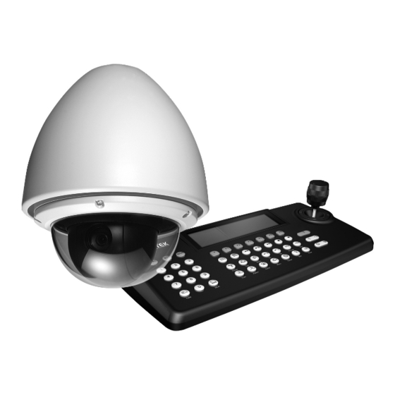
VT-PTZ Series
Xpress Dome with 18x, 26x
or 36x Optical Zoom
Advertisement
Table of Contents

Related Manuals for Vitek VT-PTZ10


Summary of Contents for Vitek VT-PTZ10
- Page 1 • True Night Shot (D/N) Function with Automatic Cut Filter (VT-PTZ26 & VT-PTZ36) • Built-in 36x Optical Zoom / 12x Digital Zoom (VT-PTZ36), Built-in 26x Optical Zoom / 12x Digital Zoom (VT-PTZ26) or 18x Optical Zoom / 12x Digital Zoom (VT-PTZ18) •...
-
Page 2: Content Verification
3. One Instruction Manual. 4. Three Mounting Screws. 5. Three Plastic Anchors. 6. One Three-Pin Connector. 7. One Four-Pin Connector. 8. Two Eight-Pin Cable Assemblies. If any of the contents are missing, please contact the Vitek Customer Help Desk immediately. -
Page 3: Risk Of Electrick Shock Warning
RISK OF ELECTRICK SHOCK WARNING WARNING TO REDUCE THE RISK OF FIRE OR ELECTRIC SHOCK, DO NOT EXPOSE THIS PRODUCT TO RAIN OR MOISTURE. DO NOT INSERT ANY METALLIC OBJECTS THROUGH THE VENTILATION GRILLS OR OTHER OPENINGS ON THE EQUIPMENT. CAUTION EXPLANATION OF GRAPHICAL SYMBOLS The lightning flash with arrowhead symbol, within an equilateral triangle, is intended to... -
Page 4: Disclaimer
Vitek Industrial Video Products, Inc. • Vitek makes no warranties for damages resulting from corrupted or lost data due to a mistaken operation or malfunction of the Xpress Domes, the software, keyboard joystick controller, personal computers, peripheral devices, or unapproved/unsupported devices. -
Page 5: Fcc Notice
Vitek Industrial Video Products, Inc. 28492 Constellation Road Valencia, CA 91355 Phone: (888) VITEK-70 / (818) 771-0300 Fax: (818) 771-0400 www.vitekcctv.com | Sales@vitekcctv.com Canadian Radio Interference Regulations This is a Class A apparatus complies with Canadian ICES-003. -
Page 6: Read This First
Before you try to record important subjects, we highly recommend that you make several test sessions to ensure that the Xpress Dome is operating and being operated correctly. Please note that Vitek Industrial Video Products, Inc., its subsidiaries and affiliates, and its distributors are not liable for any consequential damages arising from any malfunction of the Xpress Dome or its accessories. -
Page 7: Safety Precautions
Speed Dome. Immediately turn the Speed Dome’s power off or unplug the power cord from the power outlet. authorized by the equipment distributor or a Vitek customer help desk. Do not attempt to disassemble or alter any part of the equipment that is not expressly described in this guide. - Page 8 VT-PTZ Series Do not use substances containing alcohol, benzene, thinners or other flammable substances to clean or maintain the equipment. The use of these substances may lead to fire. Use a dry cloth on a regular periodic basis and wipe away the dust and dirt that collects on the device.
-
Page 9: Caution
CAUTION Avoid using, placing or storing the equipment in places subject to strong sunlight or high temperatures, such as the greenhouse or trunk of a car. Exposure to intense sunlight and heat may cause the battery to leak, overheat or explode, resulting in fire, burns or other injuries. -
Page 10: Table Of Contents
VT-PTZ Series CONTENT VERIFICATION... 1 RISK OF ELECTRICK SHOCK WARNING ... 2 DISCLAIMER... 3 FCC NOTICE ... 4 READ THIS FIRST ... 5 Test Sessions... 5 The Privacy act of 1974 (5 U.S.C. § 552a) ... 5 Warranty Limitations... 5 SAFETY PRECAUTIONS... - Page 11 3.1.3.3 Deleting a programmed pattern..35 3.1.3.4 Save and Exit ... 35 3.1.4 SCAN (VECTOR SCAN)..36 3.1.4.1 Programming a SCAN..36 3.1.4.2 Alternate method of programming a scan..38 3.1.4.3 Direction..39 3.1.4.4 Swap... 39 3.1.4.5 Save and Exit ...
- Page 12 VT-PTZ Series 3.4.1.1 Mode ... 63 3.4.1.2 AF Sensitivity (Automatic Focus Sensitivity) ... 64 3.4.2 WB CONTROL (WHITE BALANCE CONTROL)... 64 3.4.2.1 Mode ... 64 3.4.2.2 R Gain (Red Gain)... 65 3.4.2.3 B Gain (Blue Gain) ... 65 3.4.2.4 Exit ... 65 3.4.3 AE CONTROL (AUTOMATIC EXPOSURE CONTROL)...
- Page 13 3.5.9 SYSTEM INFORMATION... 81 3.5.10 EXIT ... 81 V. GLOSSARY ... 83 VI. FUNCTION SHORTCUTS... 86 VT-PTZ Series...
-
Page 14: Introduction
VT-PTZ Series I. INTRODUCTION 1.1 FEATURES The Xpress Dome features lowlight sensitivity. User friendly, on-screen pull-down menus and short-cuts make it easy to setup and program functions. System information aides trouble shooting by displaying the hardware and software version of the dome driver, baud rate, and protocol. Mechanism Built-in 18 (VT-PTZ18) and 26 (VT-PTZ26) times optical power zoom camera and 12 times digital zoom. - Page 15 Movement 64 steps of variable speed from 0.1°/sec to 90°/sec. Max manual speed 360°/sec with Turbo key pressed, Preset speed is 380°/sec. Minimum adjustable angle is 0.0375° with SingleStep move function. Programmable user preferences of speed (Slow, Medium, Fast). Connection Addressable up to 999 camera IDs (Extendable up to 3999 in factory mode).
-
Page 16: System Configuration And Connection
VT-PTZ Series 1.2 SYSTEM CONFIGURATION AND CONNECTION Additional joystick keyboard controllers such as the Xpress Keyboard (VT-KBD1) and a variety of external switching devices such as the Saga Series Digital Video Recorders (VT-ST and VT-XL) may be incorporated to accommodate the needs from the small to large surveillance/security system. -
Page 17: Installation
II. INSTALLATION 2.1 Connection Diagram The base of the Xpress Dome Alarm Interface A Termination Switches Address Selection Switches Protocol Selection Switches 2.2 Termination Any device that is at the end of the daisy chain must be terminated. On the Speed Dome, the dip switches can be switched to “on”... - Page 18 VT-PTZ Series The following diagram displays the dip switch settings for termination. The following diagrams are some sample examples of Termination configuration. S1:Dome1 port Termination ON SW1:Termination ON S1:Dome1 port Termination ON SW1:Termination ON SW1:Termination ON S1:Dome1 port Termination ON SW1:Termination ON S1:Dome1 port Termination ON SW1:Termination ON...
-
Page 19: Dome Camera Address (Id)
2.3 DOME CAMERA ADDRESS (ID) All devices connected in the chain must possess a unique address. If any of the devices possess the same address, then an electrical short may occur, thus damaging the control circuit and attached devices. Please be especially careful when installing multiple Speed Domes with a DVR, as it is critical that the address match the channel number of the DVR. -
Page 20: Selecting The Communication Speed
VT-PTZ Series Protocol Automatic Protocol Detection EZ, S2/E, PL, ER, PH (Even Parity) EZ, S2/E, PL, ER, PH (Odd Parity) S2/E 2.5 SELECTING THE COMMUNICATION SPEED 2.5 WIRE CONNECTIONS 2.6.1 RS485/422 Connection The Speed Dome has a built-in RS-485/422 connection so that remote control via a Keyboard Controller or a DVR is possible. -
Page 21: Alarm Connection
RS-485 ① Connect the wires to the TX+/TX- ports on the control device. ② Connect to the RX+/RX- ports on the Speed Dome. RS-422 ① Switch the RS-422 setting to “On” on the dip switch S4. ② Connect the wires to the TX+/TX- and RX+/RX- ports on the control device. ③... - Page 22 VT-PTZ Series ALARM 2 ALARM 1 1. COM A / COM B Connect the wire for the alarm output with either COM A or COM B, whether NC or NO circuits are used. 2. NC A / NC B Connect the wire for the alarm output using the normally closed circuit. The Speed Dome can trigger an alarm output using a normally closed circuit to activate a variety of external devices such as sirens, buzzers or lights.
-
Page 23: Mounting The Speed Dome
5. Alarm 1 ~ 8 Connect the wire to the appropriate alarm input. Up to eight alarm wires can be connected. 2.7 MOUNTING THE SPEED DOME Once all the dip switches and all the wiring have been properly configured, the Speed dome can be mounted in a variety of configuration using the available accessories. -
Page 24: Power On And Boot Up Sequence
VT-PTZ Series 2.8 POWER ON AND BOOT UP SEQUENCE When the Speed Dome is twisted in and locked onto the base module, it will be powered on and will run its self diagnostic boot up sequence. It will run a series of self tests on the RAM, pan and tilt and their point of origins. -
Page 25: Main Screen Display
If any of the diagnostic sequence is disturbed or is malfunctioning, then an error message will appear to the specific function. 2.9 MAIN SCREEN DISPLAY Program No. Function Title Information Alarm Display Pan & Tilt Angle VT-PTZ Series Compass Direction Dome Camera Title Dome Camera ID... -
Page 26: Programming And Operation
VT-PTZ Series III. PROGRAMMING AND OPERATION Provided that all connections are properly made, the Speed Dome which needs to be programmed must be selected before any programming is done. Please note that the Xpress Keyboard (VT-KBD1) is required to program the Xpress Dome. - Page 27 VT-PTZ Series Button or Joystick movement in Function Menu 1. Go into submenus 2. Execute a command LEFT OR RIGHT 3. Change Values 4. Navigate through menu items UP OR DOWN Navigate through menu items DOWN Complete Title editing 1. Change Value TWIST LEFT OR RIGHT 2.
-
Page 28: Function
VT-PTZ Series 3.1 FUNCTION FUNCTION menu consists of the main key functions of the Xpress Dome, where the HOME FUNCTION, PRESET, PATTER, SCAN and TOUR are configured. 3.1.1 HOME FUNCTION HOME FUNCTION is a feature where the Xpress Dome resumes automatically its programmed function after it has been idle for a specified time. -
Page 29: Number
3.1.1.2 Number 3.1.1.3 Time 3.1.1.4 Operation 3.1.1.5 Save and Exit Select the number of the programmed function to be run. Select from 10 seconds to 240 seconds after which the Xpress Dome resumes its programmed function. The default is 60 seconds. Enable or Disable the HOME FUNCTION. -
Page 30: Preset
VT-PTZ Series 3.1.2 PRESET PRESET supports up to 248 PAN, TILT, ZOOM, FOCUS and IRIS positions and settings. Once programmed, the preset points can be recalled from the keyboard controller using a combination of number keys and the PRESET button. Moreover, the preset points can be assigned to alarm actions, as HOME function, or be programmed into the TOUR. -
Page 31: Alternate Method Of Programming A Preset Position
3.1.2.2 Alternate method of programming a preset position. 3) Move the joystick around to select the desired pan, tilt and zoom position. 4) Press the FOCUS button to program the selected location. Please note that the F (Focus), I (Iris) and B (Back Light Compensation) entered as A (Automatic), A, and F (Off) respectively. -
Page 32: Deleting A Programmed Preset Position
VT-PTZ Series 3.1.2.3 Deleting a programmed preset position. 2) Press and hold down the SHIFT button and the “Select Position” will start flashing. 3) Do not let go of the SHIFT button, and move the joystick around to select the desired pan, tilt and zoom position. -
Page 33: Previous / Next Page
3.1.2.5 Previous / Next Page 3.1.2.6 Save and Exit 3.1.3 PATTERN PATTERN memorizes the movement controlled by user and duplicates the movement. The movement can be any combination of PAN, TILT and ZOOM coordinates. Up to four separate patterns can be memorized, for a maximum of 240 seconds combined. Note: The PATTERN menu can be accessed directly from the main screen by pressing the PATTERN button. -
Page 34: Programming A Pattern
VT-PTZ Series 3.1.3.1 Programming a pattern. 1) Select an empty pattern number. 2) Twist joystick programming window. “Select Position” will start flashing. Please note that the second has starts counting as soon as the program window is entered. 3) Move the joystick around and zoom in and out to create the path of the pattern. -
Page 35: Alternate Method Of Programming A Pattern
3.1.3.2 Alternate method of programming a pattern. 1) Select an empty pattern number. 2) Press and hold down the SHIFT button and the “Select Position” will start flashing. 3) Do not let go of the SHIFT button, and move the joystick and zoom in and out to create the path of the pattern. -
Page 36: Deleting A Programmed Pattern
VT-PTZ Series 3.1.3.3 Deleting a programmed pattern. 3.1.3.4 Save and Exit Note: If the total programming time reaches 240 seconds, it will automatically interrupt the programming for a short moment, and the start programming again. Previous data will be overwritten. 1) Move the joystick to highlight the desired pattern number. -
Page 37: Scan (Vector Scan)
3.1.4 SCAN (VECTOR SCAN). SCAN supports up to 16 programmed sections of angles at eight programmable speeds, also known as “Vector Scan”. “Vector Scan” shows a moving path from a starting point to an end point while panning, tilting and zooming simultaneously. In other words, the Xpress Dome is capable of moving the three coordinates while moving from one point to another. - Page 38 VT-PTZ Series 3) Select the speed of the scan. Available speeds are: 1 through 8 (8 being the fastest), Slow and Medium. The Default speed is 3. 4) Highlight START, and then twist the joystick and move the joystick to select the desired pan, tilt and zoom position.
-
Page 39: Alternate Method Of Programming A Scan
3.1.4.2 Alternate method of programming a scan. 1) Highlight START, and then press and hold the SHIFT button. 2) Do not let go of the SHIFT button, and move the joystick around to select the desired pan, tilt and zoom position 3) When the desired location is selected, let go of the SHIFT button to finish programming the starting point. -
Page 40: Direction
VT-PTZ Series 3.1.4.3 Direction. 3.1.4.4 Swap. 3.1.4.5 Save and Exit 6) When the desired location is selected, let go of the SHIFT button to finish programming the end point. Select the direction of the scan. Available options are CW (Clockwise) and CCW (Counter Clockwise). The default is CCW. -
Page 41: Tour
3.1.5 TOUR There are eight programmable Tours. positions, patterns, scans or other tours. The tours that are included in a tour are called second-level tours, which itself can be expanded to over 56 functions in a single tour. However, the second-level tours will be ignored when recalled by another tour. Please refer to the following example for better understanding. -
Page 42: Programming A Tour With Preset Programs
VT-PTZ Series 3.1.5.1 Programming a Tour with Preset Programs. 1) Select the Tour by moving the joystick left or right. 2) Twist the joystick to customize the Tour title. 3) Select an empty location. 4) Press the PRESET button. 5) When the PRESET button is pressed, first program automatically. -
Page 43: Programming A Tour With Pattern Programs
8) Repeat steps 3 through 7 for additional PRESET programs to be run. Please note that the preset programs must be preprogrammed before they can be included in the TOUR. 3.1.5.2 Programming a Tour with Pattern Programs. 6) Select from speeds, F (Fast), M (Medium) and S (Slow) for the camera movement. -
Page 44: Programming A Tour With Scan Programs
VT-PTZ Series 6) Repeat steps 1 through 5 for additional PATTERN programs to be run. Please note that the pattern programs must be preprogrammed before they can be included in the TOUR. 3.1.5.3 Programming a Tour with Scan Programs. 3) Move the joystick to the right and twist the joystick to select the pattern program. - Page 45 6) Repeat steps 1 through 5 for additional scan programs to be run. Please note that the scan programs must be preprogrammed before they can be included in the TOUR. 2) Press the SCAN button. SCAN button is pressed, the first program is entered automatically.
-
Page 46: Combining Preset, Pattern, Scan And Tour
VT-PTZ Series 3.1.5.4 Combining PRESET, PATTERN, SCAN and TOUR. 3.1.5.5 Deleting a function. 1) Using the process to enter the preset, patter and scan, any of the functions can be combined in a tour and can be run together. The example to the left shows Tour 1 which includes five preset programs, one scan program and one pattern program to be run sequentially. -
Page 47: Previous / Next Page
3.1.5.6 Previous / Next Page. 3.1.5.7 Save and Exit Highlight and move the joystick left or right to switch between the eight available pages per tour, for a total of 64 functions within a tour. Save the changes and exits to the main FUNCTION menu. -
Page 48: Alarm
VT-PTZ Series 3.2 ALARM ALARM menu configures the eight alarm inputs and two alarm outputs. The alarm inputs can be programmed to work in conjunction with any of the four functions, PRESET, PATTERN, SCAN AND TOUR to respond immediately and send the camera’s view to the designated area. - Page 49 3) Select the priority of the function. There are nine levels of priority. There is only one level 0 which overrides any other levels of priority. Level 1 through 8 can be duplicated for the rest of the alarms. 4) Select the type of the alarm input circuit. Available options are NC (Normally Closed), NO (Normally Open) and OFF.
-
Page 50: Save And Exit
VT-PTZ Series 3.2.2 SAVE AND EXIT 3.2.3 DELETING AN ALARM Save the changes and exits to the main FUNCTION menu. 1) Move the joystick to highlight the desired alarm. 2) Press the OFF button to delete the selected alarm. -
Page 51: Sample Scenario
3.2.4 SAMPLE SCENARIO As the priority and the functions settings may be confusing, please refer to the following sample scenario for a better understanding. In this scenario, let’s assume that alarms 1 through 6 are triggered simultaneously. Alarm 1 is set to priority level 0 which will execute Autoscan 1 titled as “Example001”... -
Page 52: Screen
VT-PTZ Series 3.3 SCREEN SCREEN menu consists of the screen related features, where the LANGUAGE, PRIVACY ZONE, NORTH DIRECTION, ZONE TITLE, and CAMERA TITLE are configured. 3.3.1 LANGUAGE The only available language supported at this time is English. 3.3.2 PRIVACY ZONE... -
Page 53: Programming A Privacy Zone
Privacy zones offers up to eight independent areas that can be either masked off or have the camera’s view off to prevent viewing of restricted or unwanted areas. 3.3.2.1 Programming a privacy zone. 1) Highlight a privacy zone number and twist joystick programming window. -
Page 54: Alternate Method Of Programming A Privacy Zone
VT-PTZ Series 3.3.2.2 Alternate method of programming a privacy zone. 5) Twist the joystick to enter up to 16 alphanumeric characters. 6) Select the privacy zone to be ON or OFF. 7) Select from the two types of the privacy zones, MASK or V. -
Page 55: Privacy Zones Displayed On Screen Per Type
3.3.2.3 Privacy zones displayed on screen per type. 3.3.2.4 Deleting a privacy zone. 3) Let go of the SHIFT button to finish programming the preset position. 1) Privacy zone shown when using MASK option. 2) Privacy zone shown when using V. OFF option. -
Page 56: Save And Exit
VT-PTZ Series 3.3.2.5 Save and Exit. 3.3.3 NORTH DIRECTION North direction allows the user to keep track of where the direction of North is. For example, if the Xpress Dome is installed at a location where there may be no points of references (e.g. -
Page 57: Display On / Off
3.3.3.1 Display On / Off 3.3.3.2 Position Select the North Direction display On or Off. 1) Twist programming mode. will start flashing. 2) Move the joystick around to select the new position for the north direction, and then press the FOCUS button. 3) The new position will be displayed, and DISPLAY will be automatically switched to “ON”. -
Page 58: Save And Exit
VT-PTZ Series 3.3.3.3 Save and Exit 3.3.4 ZONE TITLE There are a total of 24 available zone titles that can be programmed between specific areas. 3.3.4.1 Zone Title Display ON / OFF. 3.3.4.2 Programming a zone title. Save the changes and exits to the main SCREEN menu. - Page 59 2) Twist the joystick and “Select Position” will start flashing. Move the joystick around to select the desired pan, tilt and zoom position. 3) Press the FOCUS button to program the selected location. 4) Move the joystick to the END column of the same zone number.
-
Page 60: Alternate Method Of Programming A Zone Title
VT-PTZ Series 3.3.4.3 Alternate method of programming a zone title. 7) Move the joystick to TITLE column of the same zone number. 8) Twist the joystick to enter up to 16 alphanumeric characters for the zone title. 9) Move the Joystick up or down to finish entering the title. - Page 61 3) Let go of the SHIFT button to finish programming the START location of the zone title. 4) Move the joystick to the END column of the same zone number. 5) Press and hold the SHIFT button and “Select Position” will start flashing. Do not let go of the joystick, and it around to select the desired pan, tilt and zoom position.
-
Page 62: Previous / Next Page
VT-PTZ Series 3.3.4.4 Previous / Next Page 3.3.4.5 Save and Exit 3.3.4 CAMERA TITLE The Xpress Dome can be labeled using up to 16 alphanumeric characters. 3.3.4.1 Title Highlight and move the joystick left or right to switch between the four pages of zone title pages. There are a total of 24 zone titles available. -
Page 63: Display
3.3.4.2 Display 3.3.4.3 Position 3.3.4.4 Save and Exit Select the display mode of the camera title, ON or OFF. Select the display mode of the X and Y coordinates of the camera’s view. Save the changes and exits to the main SCREEN menu. -
Page 64: Camera
VT-PTZ Series 3.4 CAMERA CAMERA menu allows customization of the camera module installed in the Xpress Dome. The options consist of FOCUS CONTROL, WHITE BALANCE CONTROL, AUTOMATIC EXPOSURE CONTROL, BACK LIGHT COMPENSATION, SHARPNESS, DIGITAL ZOOM and CAMERA DEFAULT. 3.4.1 FOCUS CONTROL 3.4.1.1 Mode Available focus modes are AUTO and MANUAL. -
Page 65: Af Sensitivity (Automatic Focus Sensitivity)
3.4.1.2 AF Sensitivity (Automatic Focus Sensitivity) 3.4.2 WB CONTROL (WHITE BALANCE CONTROL) WB CONTROL adjusts the white balance of the picture. As different lighting conditions affect the picture differently, it enables the camera to automatically, or manually adjust to different environments for optimal picture quality. 3.4.2.1 Mode Available Automatic Focus Sensitivity modes are LOW and HIGH. -
Page 66: R Gain (Red Gain)
VT-PTZ Series 3.4.2.2 R Gain (Red Gain) 3.4.2.3 B Gain (Blue Gain) 3.4.2.4 Exit 3.4.3 AE CONTROL (AUTOMATIC EXPOSURE CONTROL) Adjust the Red Gain in MANUAL mode. Adjust the Blue Gain in MANUAL mode. Exit from the WB CONTROL. -
Page 67: Mode
AE CONTROL adjusts the exposure of the lens. As different brightnesses affect the picture differently, it enables the lens to automatically, or manually adjust to different lighting conditions for optimal brightness. 3.4.3.1 Mode 3.4.3.2 Slow Shutter 3.4.3.3 Iris 3.4.3.4 Gain Select the camera exposure mode. -
Page 68: Brightness
VT-PTZ Series 3.4.3.5 Brightness 3.4.3.6 Shutter 3.4.3.7 Exit 3.4.4 LINE LOCK CONTROL Adjust the brightness of the picture. Available options are 0 through 31. Adjust the shutter speed of the camera. Available options are 1/1 through 1/30000. Exit to the Camera Menu. -
Page 69: Mode
Line Lock allows adjusting the picture’s phase rate with other monitors, switchers, and cameras. 3.4.4.1 Mode 3.4.4.2 Phase 3.4.5 BACK LIGHT COMPENSATION Select the mode for the phase adjustment. Select the Internal mode to adjust the phase within the camera module, and select the External mode to adjust with a variety of other devices, such as monitors, switchers, cameras and multiplexers. -
Page 70: Sharpness Control
VT-PTZ Series 3.4.6 SHARPNESS CONTROL 3.4.7 DIGITAL ZOOM 3.4.8 NIGHT SHOT (VT-PTZ26 and VT-PTZ36 ONLY) Night Shot allows adjusting the camera between the day mode and the night mode. Control the sharpness of the picture digitally. Available options are 0 through 63. The default value is 9. -
Page 71: Mode
3.4.8.1 Mode 3.4.8.2 Local Control 3.4.9 CAMERA DEFAULT 3.4.10 SAVE AND EXIT Select between Auto and Manual mode. The camera will switch automatically between the day and night modes based on the environmental changes in Auto mode. The camera can be manually switched between day and night modes in Manual mode. -
Page 72: Setup
VT-PTZ Series 3.5 SETUP Setup allows customization of the mechanics of the Xpress Dome. The options consist of FLIP, SPEED, PANNING RANGE, TILT OVER ANGLE, CALIBRATION, FACTORY DEFAULT, INITIALIZE DATA, ERASE DATA and SYSTEM INFORMATION. 3.5.1 STABILIZER (VT-PTZ26 ONLY) 3.5.2 FLIP The stabilizer digitally steadies the camera to provide a smoother picture when the Xpress Dome is installed in an unstable environment (e.g. -
Page 73: Speed
3.5.3 SPEED 3.5.4 PANNING RANGE The Xpress Dome’s movement of range can be restricted depending on the environment. For example, when the Xpress Dome is installed in a corner or near a wall, it makes sense to limit the movement of the camera so that it does not look at where it is unnecessary. - Page 74 VT-PTZ Series 2) Twist the joystick to activate the programming window. “Select Position” will start flashing. Move the joystick around to select the desired pan position. 3) Press the Focus button to program the selected location. 4) Highlight the Left Pan Limit 5) Twist the joystick to activate the programming window.
-
Page 75: Alternate Method Of Programming Pan Range Limit
3.5.4.2 Alternate method of programming Pan Range Limit. 7) Switch Enable to “ON” to activate the Pan Range Limit. 8) Sometimes, the Pan Range Limit may be the opposite of the intended limits. If such is the case, simply highlight the SWAP RIGHT/LEFT and twist the joystick to swap the right and left pan limit. - Page 76 VT-PTZ Series 3) Do not let go of the SHIFT button, and move the joystick around to select the desired pan position. 4) Let go of the SHIFT button to finish programming the pan position. 5) Highlight the Left Pan Limit. 6) Press and hold down the SHIFT button and the “Select Position”...
-
Page 77: Save And Exit
3.5.4.3 Save and Exit 3.5.5 TILT OVER ANGLE Tilt Over Angle sets the limit to the horizontal view angle so that the trim ring or the housing or the ceiling does not obstruct the view of the camera. 3.5.5.1 W/O Bubble 8) Let go of the SHIFT button to finish programming the pan position. -
Page 78: With Bubble
VT-PTZ Series 3.5.5.2 On 3.5.5.3 With Bubble 3.5.6 CALIBRATION The Xpress Dome features a sensor within its mechanism to sense and retain the exact position of each and every movement so that any programmed functions and features are replicated without error time after time. However, even the most sophisticated mechanism can be presented with an anomaly due to several factors: natural disasters such as earthquakes or hurricane winds altering its point of origin, human errors (e.g. -
Page 79: Origin Reset
3.5.6.1 Origin Reset Origin Reset reverts the point of origin, or the point of reference back to when the Xpress Dome was first powered on. 3.5.6.2 Origin Position Move If the Xpress Dome needs to be replaced, then the point of origin may have to be readjusted as the point of origin will be different based on where the Xpress Dome was positioned when first powered on. -
Page 80: Origin Offset
VT-PTZ Series 3.5.6.3 Origin Offset 3.5.6.4 Auto Calibration 2) Move the joystick around to select the desired point of origin. 3) Press the FOCUS button to program the new point of origin and exit to Calibration menu. Enable or disable the point of origin offset. The default is DISABLE. -
Page 81: Save And Exit
VT-PTZ Series 3.5.6.5 Save and Exit Save the settings and exit to the Setup menu. 3.5.7 FACTORY DEFAULT Revert all settings back to factory default. 3.5.8 ERASE DATA Reset all programmed functions and features back to factory default. Origin offset value is not affected by erasing the data. -
Page 82: System Information
VT-PTZ Series 3.5.9 SYSTEM INFORMATION Displays basic information about the Xpress Dome, including the module type, hardware revision, firmware revision, protocol and the current baud rate. 3.5.10 EXIT Exit to the Main Menu screen. - Page 83 IV. SPECIFICATIONS Image Sensor Effective Pixels Horizontal Resolution 0.7 Lux 50IRE / 0.05 Lux Minimum Illumination (F1.4 Slow Shutter) F1.4(f=4.1~73.8mm Optical) Lens 18X Optical/12X Digital 4.1mm-48º(H) 73.8mm-2.8 Angle of View Shutter Speed S/N Ratio Video Output Sync System Scaning System Focus White Balance Iris Control...
-
Page 84: Glossary
VT-PTZ Series V. GLOSSARY ALARM ACTIONS The assigned responses of the dome camera when there is input status change. The dome may call Presets for each of the eight inputs. The dome reports the alarm states to the Keyboard controller for processing. AREA TITLE It is the name of the horizontal sector from a certain start point to end point of the selected dome. - Page 85 VT-PTZ Series INPUT DEVICES External devices that provide information about the condition of system components that connect to the inputs on the dome camera. Typical input devices include door contacts, motion detectors and smoke detectors. IR MODE A feature of the camera that permits manual or automatic switching between color and IR(black-and-white) operation.
- Page 86 VT-PTZ Series values for the setting range from 1/2 to 1/60. The default setting is 1/4. WHITE BALANCE Adjustments in the color hue (red and blue) gains for a camera so that true white appears white in the image. It is normally compensated for by the automatic gain control. In some lighting conditions, you may need to manually adjust the red and blue settings for optimal viewing.
-
Page 87: Function Shortcuts
VI. FUNCTION SHORTCUTS Short Cut Key Function PRST Pop up preset setup menu. TOUR Pop up guard Tour setup menu. PTRN Pop up Pattern setup menu. Pop up Auto Scan setup menu. SCAN No.+ PGM +PRST Store the current view at the selected number. No.+ PGM +TOUR Pop up tour setup menu at the selected number. - Page 88 28492 CONSTELLATION ROAD VALENCIA, CA 91355 WWW.VITEKCCTV.COM | 888-VITEK-70...
Need help?
Do you have a question about the VT-PTZ10 and is the answer not in the manual?
Questions and answers