Table of Contents
Advertisement
Quick Links
• 1/2.9" Sony® CMOS
• 2.1 MegaPixel With full 1080p/720p Output
• Up to 30fps live view@ 1920x1080 (1080p)
• MegaPixel IR Corrected 9-22mm Varifocal Lens
• Mechanical IR Cut Filter (True Day/Night)
• H.264/MJPEG Dual Streaming
• 16:9 Video format
• On-board Intelligence (OBI Technology) delivers Auto-Focus-Zoom by tracking
motion, then optically zooming in to that area of the frame
• 6 High Power 850nm IR LEDs with up to 300' IR range
• Fully programmable advanced WDR
• Onvif Compliance
• Integrated Cooling Fan
• Standard SD memory card slot for Local recording
• Advanced OSD Functions: Motion Activated Pointing Zoom, Defog, Dynamic IR,
BLC/HLC, Motion Deblur, Pixel Defect Compensation, Title Set, Mirror, Flip
• Heavy Duty IP68 rated weather/vandal resistant aluminum construction
• 12VDC / 24VAC & PoE (Power over Ethernet) Operation
Specifications & installation procedure subject to change without notice.
Visit www.vitekcctv.com for the most current information available.
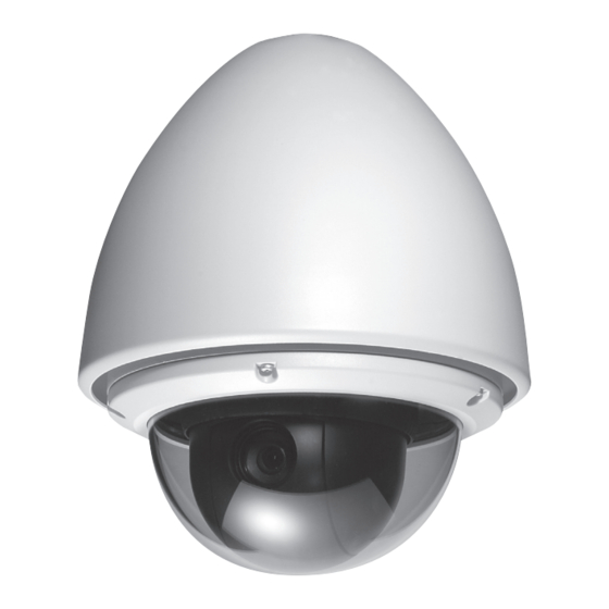
VT-PTZ40WH
960H Xpress Dome with 40X
Optical Zoom and Advanced WDR
Advertisement
Table of Contents

Related Manuals for Vitek VT-PTZ40WH


Summary of Contents for Vitek VT-PTZ40WH
- Page 1 VT-PTZ40WH 960H Xpress Dome with 40X Optical Zoom and Advanced WDR • 1/2.9” Sony® CMOS • 2.1 MegaPixel With full 1080p/720p Output • Up to 30fps live view@ 1920x1080 (1080p) • MegaPixel IR Corrected 9-22mm Varifocal Lens • Mechanical IR Cut Filter (True Day/Night) •...
-
Page 2: Disclaimer
Vitek. Vitek makes no warranties for damages resulting from corrupted or lost data due to a • mistaken operation or malfunction of the Speed Dome Cameras, peripheral devices, or... -
Page 3: Warning And Caution
VT-PTZ Series WARNING AND CAUTION WARNING TO REDUCE THE RISK OF FIRE OR ELECTRIC SHOCK, DO NOT EXPOSE THIS PRODUCT TO RAIN OR MOISTURE. DO NOT INSERT ANY OBJECT THROUGH THE VENTILATION GRILLS OR OPENINGS ON THE EQUIPMENT. CAUTION The lightning flash with arrowhead symbol, within an equilateral triangle, is intended to alert the user to the presence of uninsulated “dangerous voltage”... -
Page 4: Fcc Compliance Statement
VT-PTZ Series FCC COMPLIANCE STATEMENT FCC INFORMATION: THIS EQUIPMENT HAS BEEN TESTED AND FOUND TO COMPLY WITH THE LIMITS FOR A CLASS A DIGITAL DEVICE, PURSUANT TO PART 15 OF THE FCC RULES. THESE LIMITS ARE DESIGNED TO PROVIDE REASONABLE PROTECTION AGAINST HARMFUL INTERFERENCE WHEN THE EQUIPMENT IS OPERATED IN A COMMERCIAL ENVIRONMENT. -
Page 5: Important Safeguards
VT-PTZ Series IMPORTANT SAFEGUARDS 1. Read these instructions. 2. Heed all warnings. 3. Follow all instructions. 4. Do not use this equipment near water. 5. Clean only with dry cloth. 6. Do not block any ventilation openings. Install in accordance with the manufacturer's instructions. -
Page 6: Table Of Contents
VT-PTZ Series TABLE OF CONTENTS DISCLAIMER_________________________________________________________1 WARNING AND CAUTION___________________________________________________2 FCC COMPLIANCE STATEMENT_____________________________________________3 CE COMPLIANCE STATEMENT______________________________________________3 IMPORTANT SAFEGUARDS_________________________________________________4 CONTENT VERIFICATION __________________________________________________7 MENU TREE _____________________________________________________________8 INTRODUCTION__________________________________________________________9 INSTALLATION AND CONFIGURATION______________________________________10 Typical system configuration _____________________________________________10 Basic configuration of speed dome camera system____________________________11 Connecting the Speed Dome directly into the DVR____________________________12 Connecting the Speed Dome into the Controller via j-box_______________________12 Connecting both Speed Dome and DVR via J-BOX___________________________13 Setting the Video System________________________________________________14... - Page 7 VT-PTZ Series TABLE OF CONTENTS 3.4 Zone Title_______________________________________________________41 3.5 Camera Title_____________________________________________________42 3.6 OSD Display_____________________________________________________42 4 CAMERA SETUP____________________________________________________43 4.1 Focus Control____________________________________________________43 4.2 WB (white balance) _______________________________________________43 4.3 AE Control______________________________________________________45 4.4 Night Shot Menu__________________________________________________46 4.5 Camera Default__________________________________________________46 5 TIME & DATE SETUP________________________________________________47 5.1 Edit Daylight Savings______________________________________________47 5.2 Edit Holidays_____________________________________________________48 5.3 List Holiday______________________________________________________49...
-
Page 8: Content Verification
1. One Xpress Dome Camera 2. One Instruction Manual 3. Three Mounting Screws. 4. Three Plastic Anchors. 5. Two Eight-Pin Cable Assemblies. If any of these materials are missing, please contact the vendor or Vitek customer help desk immediately. -
Page 9: Menu Tree
VT-PTZ Series MENU TREE 1.1 HOME FUNCTION (MENU [ Functions [ Home) 1. FUNCTIONS 1.2 PRESET (MENU [ Functions [ Preset Shortcut : PRST) (MENU [ Function [ Pattern or Shortcut: PTRN) 1.3 PATTERN 1.4 SCAN (MENU [ Functions [ Scan or Shortcut: SCAN) 1.5 TOUR (MENU [... -
Page 10: Introduction
VT-PTZ Series INTRODUCTION Features The Speed Dome Camera features a high resolution EX-View HAD CCD imager for enhanced lowlight sensitivity. User friendly, on-screen pull-down menus and short-cuts make it easy to setup and program functions. System information aides trouble shooting by displaying the hardware and software version of the camera’s firmware version, baud rate, and protocol. -
Page 11: Installation And Configuration
VT-PTZ Series INSTALLATION AND CONFIGURATION Typical system configuration Additional Speed Dome joystick controllers and a variety of external switching devices such as multiplexers (MUXes) and Digital Video Recorders (DVRs) may be incorporated to accommodate the needs from a small to a large surveillance/security system. Figure 1 illustrates sample installation. -
Page 12: Basic Configuration Of Speed Dome Camera System
VT-PTZ Series INSTALLATION AND CONFIGURATION Basic configuration of speed dome camera system Figure 2 - Basic Installation Diagram... -
Page 13: Connecting The Speed Dome Directly Into The Dvr
VT-PTZ Series INSTALLATION AND CONFIGURATION Connecting the Speed Dome directly into the DVR • Locate the RS485 + & - conductor wire from the Speed Dome Camera. · Connect the + & - into the Tx+ & Tx- ports of the DVR. Tx+ & Tx- ports can be found in the rear part of the DVR. -
Page 14: Connecting Both Speed Dome And Dvr Via J-Box
VT-PTZ Series INSTALLATION AND CONFIGURATION Connecting both Speed Dome and DVR via J-BOX Figure 5 - Connecting Camera & DVR into Controller... -
Page 15: Setting The Video System
VT-PTZ Series INSTALLATION AND CONFIGURATION The dome camera must be installed by qualified service personnel. Before installing the dome camera system, this instruction manual must be read thoroughly and understood fully. Dome cameras must be set up properly before starting the installation. This involves properly setting configuration switches. -
Page 16: Setting The Web Baudrate
VT-PTZ Series INSTALLATION AND CONFIGURATION Setting the Web Baud rate Set baud rate of communication between control board and IP board. 4800 9600 19200 38400 Figure 8 - Setting the baud rate Principle of Termination Every device that is connected at the end of the communication data line must be terminated by either the DIP switch setting or an appropriate device such as a termination jumper to prevent potential control signal errors. - Page 17 VT-PTZ Series INSTALLATION AND CONFIGURATION Figure 10 - Termination Diagram...
-
Page 18: Dome Camera Address (Id)
VT-PTZ Series INSTALLATION AND CONFIGURATION Dome Camera Address (ID) Each dome camera must have a unique address (ID). Identical IDs on the same line may damage the control circuit caused by an electrical short. When installing multiple dome cameras on a DVR, it is recommended that the dome camera ID’s be identical to the camera port of the DVR. -
Page 19: Setting Protocols
VT-PTZ Series INSTALLATION AND CONFIGURATION Setting Protocols A Speed Dome camera is capable of negotiating with multiple protocols if the communication speed is matched (same baud rate i.e., 9600 bps). See Figure 13 for the appropriate protocol switch settings. Note: Consult service personnel if a dome camera is installed with a device other than a recommended Speed Dome Controller. -
Page 20: Connections
VT-PTZ Series INSTALLATION AND CONFIGURATION Connections How to Connect RS485 The dome camera has a built-in RS-485 receiver so that it can be controlled remotely by an external control device such as a joystick controller or a DVR. RS-485: Connect the TXA (Tx+) and TXB (Tx-) of the RS485/422 control devices (KBD, DVR…) to RXA (RX+), RXB (RX-) of the dome camera. -
Page 21: Mounting The Dome Camera
VT-PTZ Series INSTALLATION AND CONFIGURATION Mounting the Dome Camera Once all DIP switches are set properly and all external connections are made, the dome camera can be mounted. The Speed Dome camera is designed to mount on a structural body supporting loads up to 11lbs (5 Kg.) See Figure 14 Figure 14 - Example of a ceiling mounted installation... -
Page 22: Power On And Boot-Up Sequence
VT-PTZ Series INSTALLATION AND CONFIGURATION Power on and Boot-up Sequence When power is applied to the dome camera, it will start the boot-up sequence. When boot- up is done, the following information is displayed on the monitor screen. XPRESS DOME 2700 On Screen Display in normal control mode 00/00/0000 00:00:00 AM... -
Page 23: Program & Operation
VT-PTZ Series PROGRAM & OPERATION Dome Camera Selection Prior to start of programming or operating the dome camera, please make sure that both the camera and the joystick controller are communicating. In order for changes to take effect for the camera, particular camera’s ID must be selected on the controller. Example: Pressing 1, 6 and CAM key sequentially will select dome camera 16. -
Page 24: Functions
VT-PTZ Series PROGRAM & OPERATION 1. FUNCTIONS (MENU =>Functions) By pressing the MENU button on the keyboard controller, the following On-screen MAIN MENU will be shown on the monitor screen. Select the Functions ICON and then twist the Joystick CCW/CW (counterclockwise / clockwise) to access Functions menu. -
Page 25: Home Function
VT-PTZ Series PROGRAM & OPERATION 1.1 HOME FUNCTION (MENU =>Functions => Home) After Home item has been selected, follow the directions below to set Home function. Ÿ Function: Tour/ Preset/ Pattern/ Scan Ÿ Number: - - - Ÿ Time: 10~240 Seconds Ÿ... -
Page 26: Preset
VT-PTZ Series PROGRAM & OPERATION 1.2 PRESET (MENU => Functions => Preset Shortcut: PRST) Preset stores pan, tilt, zoom, focus and iris settings. Once programmed, pressing combination of 0 ~9 numbers and the Preset button on the controller should automatically call up the preset position. - Page 27 VT-PTZ Series PROGRAM & OPERATION 7. Select the desired character/digit on the title line by moving the joystick Left/Right 8. Move the cursor to the desired character on the character table using Joystick Up/ Down/ Left /Right, then twist the Joystick CCW/CW at the desired character to complete selection, then the cursor position on the title moves to the next position automatically.
- Page 28 VT-PTZ Series PROGRAM & OPERATION Ÿ Sensitivity : 1-16(most sensitive) Ÿ Hold Time: 03-99SEC: The hold time starts to count after motion is detected. Ÿ Output: OFF, relay output: R01, R02 Ÿ Position : motion detection area ALL (full screen), AREA (area defined in the area setup) *Motion Setup is only available from Preset 1 to Preset 16 Ÿ...
- Page 29 VT-PTZ Series PROGRAM & OPERATION To enter Advanced Motion Setup, twist the Joystick CCW/CW on Motion Setup. Ÿ Mode: select tracking mode ACTION1: Once motion is detected, the camera starts and continues tracking until 5seconds after no motion is detected, then camera runs Lost Action. ACTION2: Once motion is detected, the camera starts and follows the object for 5 seconds.
-
Page 30: Scan
VT-PTZ Series PROGRAM & OPERATION 1.3 SCAN (MENU => Functions => Scan or Shortcut: SCAN) The Scan function supports up to 16 programmed sections of angles at 8 programmable speeds. Ÿ SPEED (MODE) 1: SLOWER ↔ 8 FASTER Diagonal Scan shows moving path from start point to end point including tilt and zoom** simultaneously. -
Page 31: Tour
VT-PTZ Series PROGRAM & OPERATION 6. DIR: Move the Joystick downward to select direction of rotation. Tap joystick left/ right or twist CCW/CW to select direction of Scan 7. Swap: Move the Joystick downward to swap. This will switch the start and end position. Tap joystick left/ right or twist CCW/CW to swap the start and end position 8. - Page 32 VT-PTZ Series PROGRAM & OPERATION ŸTitle: 16 digits of title for tour label Ÿ - - - : blank preset position Ÿ SP: F-Normal/ M- Medium D.Scan/ S- Slowest D.Scan Ÿ DW: 03-99 Sec Ÿ Prst: PRESET 1~248 Ÿ Ptrn: PATTERN 1~8 Ÿ...
-
Page 33: Pattern
VT-PTZ Series PROGRAM & OPERATION 1.5 PATTERN (MENU => Function => Pattern or Shortcut: PTRN) The Pattern function memorizes and stores movement of the selected dome camera for up to 480 seconds. A total of 480 seconds is allotted for all 8 patterns. Stored pattern is played back by pressing No. -
Page 34: Actions Setup
VT-PTZ Series PROGRAM & OPERATION 2. ACTIONS SETUP (MENU => Actions Setup) 2.1 ALARM ACTION SETUP (MENU => Actions Setup => Alarm) Highlight Alarm in the action setup and twist joystick or tap joystick to the right to access Alarm Setup menu Ÿ... -
Page 35: Alarm List
VT-PTZ Series PROGRAM & OPERATION There are 9 levels of priority. 0= Highest priority, supports repeated/dedicated functions like a Pattern (Pxx), Tour (Txx), Scan (Sxx). 1~8: Same level of alarm calls presets one after the other. Ex) Alarm 01 calls Pattern 01, after alarm 01 is released alarm 02, 03 will call preset 48 and preset 01 1. -
Page 36: Clear Alarm List
VT-PTZ Series PROGRAM & OPERATION 2.3 CLEAR ALARM LIST (MENU => Actions Setup => Clear Alarm List) Select “YES” to clear the alarm list. 2.4 SCHEDULE ACTION SETUP (MENU => Actions Setup => Schedule Action Setup) The schedule action setup allows you to program a function at a specific date and time. Ÿ... - Page 37 VT-PTZ Series PROGRAM & OPERATION Ÿ Add Action To List: Add the current Schedule to the list Ÿ Delete Action: Delete the current Schedule from the list Follow the steps below to program the schedule action: Create a new action: 1.
- Page 38 VT-PTZ Series PROGRAM & OPERATION When you program the first only, the camera always operates in B/W mode. So don’t forget to program the second action for daytime. NOTE: The function of Day / Night (D/N: COLOR, D/N: B/W, D/N: AUTO) changes the camera menu setting and doesn’t affect the preset.
-
Page 39: List Action
VT-PTZ Series PROGRAM & OPERATION 2.5 LIST ACTION (MENU => Actions Setup => List Action) List action type: ALL, Preset, Scan, Pattern, Tour, Auto Pan, Day/Night, Alarm Out, Alarm In 1. Select the list action by moving the Joystick up or down. 2. -
Page 40: Screen
VT-PTZ Series PROGRAM & OPERATION SCREEN (MENU => Screen) By pressing the MENU button on the keyboard controller, the following On-screen MAIN MENU will be shown on the monitor screen. Highlight Screen and then twist the Joystick CCW/CW to enter Screen menu. 3.1 LANGUAGE SETUP (MENU =>... -
Page 41: Privacy Zone Setup
VT-PTZ Series PROGRAM & OPERATION 3.2 PRIVACY ZONE SETUP (MENU => Screen => Privacy Zone) Highlight Privacy Zone and then move the joystick to the right to enter the menu. This function disables the viewing of restricted areas for privacy reasons. It offers masking up to 8 unwanted views in a camera. -
Page 42: Zone Title
VT-PTZ Series PROGRAM & OPERATION 3.4 ZONE TITLE (MENU => Screen =>Zone Title) Enter a specific name in sectioned angle between Start and End. 1. Press MENU => Screen => Zone Title to display zone title menu on the monitor. 2. -
Page 43: Camera Title
VT-PTZ Series PROGRAM & OPERATION 3.5 CAMERA TITLE (MENU => Screen => Camera Title) This function allows the users to set the title for the camera as well as the usage of on screen display Twist the joystick handle on Camera Title. Select alphanumeric characters by rotating the handle. -
Page 44: Camera Setup
VT-PTZ Series PROGRAM & OPERATION 4. CAMERA SETUP (MENU => Camera) NOTE: The menu features will vary depending on the camera module. Ÿ Back Light: Objects in front of bright backgrounds will be clearer with BLC ON. NOTE: The Back Light operates in AUTO mode only. Ÿ... -
Page 45: Wb (White Balance)
VT-PTZ Series PROGRAM & OPERATION Ÿ AF Sensitivity: NORMAL / LOW NORMAL: Use this option when viewing fast motion. LOW: Offers better focus stability. In low light conditions, Auto Focus stops operation even when brightness changes, enabling stable images of moving objects. Ÿ... -
Page 46: Ae Control
VT-PTZ Series PROGRAM & OPERATION 4.3 AE CONTROL (MENU => Camera => AE Control) Ÿ Mode : AUTO / MANUAL / SHUTTER / IRIS / BRIGHT AUTO: Auto Iris and Gain, Fixed Shutter speed (NTSC: 1/60 sec, PAL: 1/50 sec) MANUAL: Variable Shutter, Iris and Gain. -
Page 47: Night Shot Menu
VT-PTZ Series PROGRAM & OPERATION 4.4 NIGHT SHOT MENU (MENU => Camera =>Night Shot) The Night Shot option removes the IR Cut filter of the camera and makes the camera sensitive to near infrared light. If Night Shot mode of the selected camera is set to Manual, 10+ ON will enable the Night Shot mode, 10+ OFF will turn off the Night Shot mode. -
Page 48: Time & Date Setup
VT-PTZ Series PROGRAM & OPERATION 5. TIME/DATE SETUP (MENU => Time & Date) Note: When installing the dome for the first time the clock will not operate until date and time are set. The date and time can be displayed on the monitor when the Date/Time option is set to ON in the display menu. -
Page 49: Edit Holidays
VT-PTZ Series PROGRAM & OPERATION 5.2 EDIT HOLIDAYS (MENU => Time & Date => Edit Holidays) You can add up to 50 holidays. Use the following steps to create a holiday. 1. Select “NEW” by twisting the joystick or tap to the right at the field. 2. -
Page 50: List Holiday
VT-PTZ Series PROGRAM & OPERATION Use the following steps to delete the holiday. 1. Select the number to delete. 2. Select “Delete Holiday” and twist or tap the Joystick to right. 3. Select “YES” and twist or tap the Joystick to right then the next number displays at the number field. -
Page 51: Data Setup
VT-PTZ Series PROGRAM & OPERATION 6. DATA SETUP (MENU => Data Setup) 6.1 FACTORY DEFAULT (MENU => Data Setup => Factory Default) The factory default returns programmed data to initial state as ex-factory except the followings. Ÿ Time and date Ÿ... -
Page 52: Erase Programmed Data
VT-PTZ Series PROGRAM & OPERATION 6.2 ERASE PROGRAMMED DATA (MENU => Data Setup => Erase Programmed Data) Erase programmed data in the EEPROM of the selected dome camera. Origin offset value is not affected. 1. Set the option to “ON” for the one you want to erase 2. -
Page 53: Restore Data
VT-PTZ Series PROGRAM & OPERATION 6.4 RESTORE DATA (MENU => Data Setup => Restore Data) This function restores the setting values of the dome from the backup memory to the dome. 6.5 CLEAR DATA (MENU => Data Setup => Clear Data) This function clears all data of the backup memory. -
Page 54: Setup
VT-PTZ Series PROGRAM & OPERATION 7. SETUP (MENU => Setup) 7.1 PRESET FREEZE (MENU => Setup => Preset Freeze) Ÿ ON: the image is frozen during calling preset. 7.2 SPEED (MENU => Setup => Speed) User can select preferable speed of manual control. (SLOW / MEDIUM / FAST) 7.3 RESPONSE (MENU =>... -
Page 55: Flip
VT-PTZ Series PROGRAM & OPERATION 7.4.1 FLIP (MENU => Setup =>Dome Angle=>Flip) When the Speed Dome camera is mounted on a ceiling, it can track a moving target in a path directly below the camera: ON: When the camera reaches the moving object directly below the dome, the dome Camera tracks the object smoothly with a digitally corrected image. -
Page 56: Calibration
VT-PTZ Series PROGRAM & OPERATION This option is used to set the limit of the horizontal view angle so that the trim ring or ceiling does not obstruct the horizontal image when zooming out (wide angle). ON: In some installations it is desirable for the dome camera to be able to see above the horizon. -
Page 57: Password Setup
VT-PTZ Series PROGRAM & OPERATION 7.6 PASSWORD SETUP (MENU => Setup =>Password) You can change the password to a 4-digit / character in this menu. The default password is 9999. Edit Password 1. Select edit password using the joystick. 2. Select the desired number using the joystick up and down, and then twist the joystick handle. -
Page 58: System Information
VT-PTZ Series PROGRAM & OPERATION 7.7 SYSTEM INFORMATION (MENU => Setup => System Information) 2700 This screen shows information of the dome camera for service or trouble shooting... -
Page 59: Technical Specifications
VT-PTZ Series TECHNICAL SPECIFICATIONS Image Sensor 1/4" Sony Super HAD II CCD Horizontal Resolution 670 TV Lines (960H) Minimum Illumination 0.04 Lux (f1.4) / 0.01 Lux (With IR Cut Filter Removed) Lens 3.06mm to 122.4mm (F1.6~F4.6) View angle 60.0° (@ 3.06mm) to 1.6° (@ 122.4mm) Optical Zoom Digital Zoom Shutter Speed... -
Page 60: Dimension
VT-PTZ Series TECHNICAL SPECIFICATIONS Dimension Figure 16-Dimension... -
Page 61: Appendix
VT-PTZ Series APPENDIX Troubleshooting If problems occur, verify the installation of the camera with the instructions in this manual. Isolate the problem from the equipments in the system and refer to the equipment manual for further information. Problem Solution Verify that power is connected to all components in the system. -
Page 62: Limited Product Warranty
VITEK products carry a three (3) year limited warranty. VITEK warrants to the purchaser that products manufactured by VITEK are free of any rightful claim of infringement or the like, and when used in the manner intended, will be free of defects in materials and workmanship for a period of three (3) years, or as otherwise stated above, from the date of purchase by the end user.
Need help?
Do you have a question about the VT-PTZ40WH and is the answer not in the manual?
Questions and answers