Sign In
Upload
Download
Table of Contents
Contents
Add to my manuals
Delete from my manuals
Share
URL of this page:
HTML Link:
Bookmark this page
Add
Manual will be automatically added to "My Manuals"
Print this page
×
Bookmark added
×
Added to my manuals
Manuals
Brands
Kramer Manuals
Matrix Switcher
VS-626
User manual
Kramer VS-626 User Manual
6x6 video/audio matrix switcher; 8x8 video/audio matrix switcher
Hide thumbs
1
Table Of Contents
2
3
4
5
6
7
8
9
10
11
12
13
14
15
16
17
18
19
20
21
22
23
24
25
26
27
28
page
of
28
Go
/
28
Contents
Table of Contents
Bookmarks
Table of Contents
Table of Contents
1 Introduction
2 Getting Started
Quick Start
3 Overview
4 Your VS-626 (VS-828) Video Audio Matrix Switcher
Figure 1: VS-626 6X6 Video / Audio Matrix Switcher
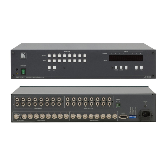
Figure 2: VS-828 8X8 Video / Audio Matrix Switcher
Table 1: Front Panel VS-626 6X6 (VS-828 8X8) Video / Audio Matrix Switcher Features
Table 2: Rear Panel VS-626 6X6 (VS-828 8X8) Video / Audio Matrix Switcher Features
5 Installing on a Rack
6 Connecting the VS-828 Video / Audio Matrix Switcher
Figure 3: Connecting the Video Sources and Acceptors to the Rear Panel
Setting the Dipswitches
SELF ADDRESS Dipswitches
Figure 4: VS-626 (VS-828) Dipswitch Configuration
Table 3: Dipswitch Settings
Table 4: Self Address Dipswitch Settings
Setting Connection Dipswitches
Controlling Via RS-232 (for Example, Using a PC)
Figure 5: Connecting a PC Without Using a Null-Modem Adapter
Controlling Via RS-232 and RS-485
Figure 6: RS-232 and RS-485 Operation
RGB/YUV Switching with RS-232 (PC Control)
Figure 7: RGB Switching with RS-232 Control Via a PC
7 Operating VS-828 Matrix Switcher
Displaying Unit Characteristics
Selecting and Connecting an Output And/Or Input
Choosing the Audio-Follow-Video or Breakaway Option
Setting the Audio-Follow-Video Option
Setting the Breakaway Option
Storing/Recalling Input/Output Configurations
Storing an Input/Output Configuration
Recalling an Input/Output Configuration
Deleting an Input/Output Configuration
Resetting the Machine
8 Technical Specifications
Table 5: Technical Specifications of the VS-626 / VS828
9 Communication Protocol
Table 6: Protocol Definitions
10 Table of Hex Codes for the Master VS-828
Advertisement
Quick Links
Download this manual
Kramer Electronics, Ltd.
USER MANUAL
Models:
VS-626
, 6x6 Video / Audio Matrix Switcher
VS-828
, 8x8 Video / Audio Matrix Switcher
Table of
Contents
Previous
Page
Next
Page
1
2
3
4
5
Advertisement
Table of Contents
Need help?
Do you have a question about the VS-626 and is the answer not in the manual?
Ask a question
Questions and answers
Related Manuals for Kramer VS-626
Matrix Switcher Kramer VS-62H User Manual
6x2 hdmi matrix switcher (50 pages)
Matrix Switcher Kramer VS-62H User Manual
6x2 hdmi matrix switcher (51 pages)
Matrix Switcher Kramer VS-62DT Quick Start Manual
Uhd matrix switcher (4 pages)
Matrix Switcher Kramer VS-62DT User Manual
6x2 uhd matrix switcher hdmi to hdmi & hdbaset with poe (82 pages)
Matrix Switcher Kramer VS-62HA User Manual
6x2 hdmi/audio matrix switcher (95 pages)
Matrix Switcher Kramer VS-62HA Quick Start Manual And Manual
(2 pages)
Matrix Switcher Kramer VS-622DT Quick Start Manual
(4 pages)
Matrix Switcher Kramer VS-606xl User Manual
(31 pages)
Matrix Switcher Kramer VS-606xl User Manual
Video/audio matrix switcher (40 pages)
Matrix Switcher Kramer VS-66H3 User Manual
6x6 hdmi matrix switcher (27 pages)
Matrix Switcher Kramer VS-402xl User Manual
Vs-402xl, 4x2 vertical interval video-audio matrix switcher vs-602xl, 6x2 vertical interval video-audio matrix switcher (27 pages)
Matrix Switcher Kramer VS-66HN User Manual
6x6 hdmi matrix switcher (36 pages)
Matrix Switcher Kramer VS-66H User Manual
6x6 hdmi matrix switcher (24 pages)
Matrix Switcher Kramer VS-6464DN User Manual
64x64 digital matrix switcher (48 pages)
Matrix Switcher Kramer VS-6464DN User Manual
64x64 digital matrix switcher (57 pages)
Matrix Switcher Kramer VS-88UHD User Manual
Uhd matrix switcher (84 pages)
This manual is also suitable for:
Vs-828
Table of Contents
Print
Rename the bookmark
Delete bookmark?
Delete from my manuals?
Login
Sign In
OR
Sign in with Facebook
Sign in with Google
Upload manual
Upload from disk
Upload from URL


Need help?
Do you have a question about the VS-626 and is the answer not in the manual?
Questions and answers