Table of Contents
Advertisement
Quick Links
Download this manual
See also:
User Manual
Advertisement
Table of Contents

Related Manuals for Kramer VS-606xl


Summary of Contents for Kramer VS-606xl
- Page 1 KRAMER ELECTRONICS, Ltd. USER MANUAL MATRIX SWITCHERS Models: VS-606xl, VS-646 VS-808xl, VS-804xl, VS-848 IMPORTANT: Before proceeding, please read paragraph entitled "Unpacking and Contents" KRAMER ELECTRONICS, LTD.
-
Page 2: Table Of Contents
HOW DO I GET STARTED? UNPACKING AND CONTENTS Optional Accessories GETTING TO KNOW YOUR MATRIX SWITCHER Your VS-606xl and VS-646 Matrix Switchers Features of the VS-606xl and VS-646 Matrix Switchers INSTALLATION Rack Mounting CONNECTING TO VIDEO DEVICES CONNECTING TO AUDIO DEVICES... - Page 3 List Of Illustrations Figure Page VS-606xl Front/Rear Panel Features VS-646 Front/Rear Panel Features DIP switches- General View RS-232 Control Connector Wiring RS-232 and RS-485 Operation Terminating the Line Basic Video-Audio Setup RGB Switching List Of Tables Table Page VS-606xl/VS-646 Front Panel Features...
-
Page 4: Introduction
In addition to the Kramer line of high quality Matrix Switchers, such as the one you have just purchased, Kramer also offers a full line of high quality distribution amplifiers, processors, interfaces, controllers and computer-related products. This manual includes configuration, operation and option information of the following Kramer Electronics Matrix Switchers for the video professional: These "VS"... -
Page 5: Specifications
19" x 7" x 2U 19" x 7" x 2U (H x W x D) Power Source 230VAC, 50/60 Hz, 230VAC, 50/60 Hz, 230VAC, 50/60 Hz, 230VAC, 50/60 Hz, (115VAC, U.S.A.) (115VAC, U.S.A.) (115VAC, U.S.A.) (115VAC, U.S.A.) KRAMER ELECTRONICS, LTD. -
Page 6: How Do I Get Started
A built-in vertical enhancer circuit reduces noise and dot-crawl on the Y signal. In addition, the FC-10D provides an independent Y/C to Composite route, for simultaneous bi- directional operation. The Kramer FC-10D is very small in size, and is fed from an external 12VDC supply, thus ideal for fieldwork. -
Page 7: Getting To Know Your Matrix Switcher
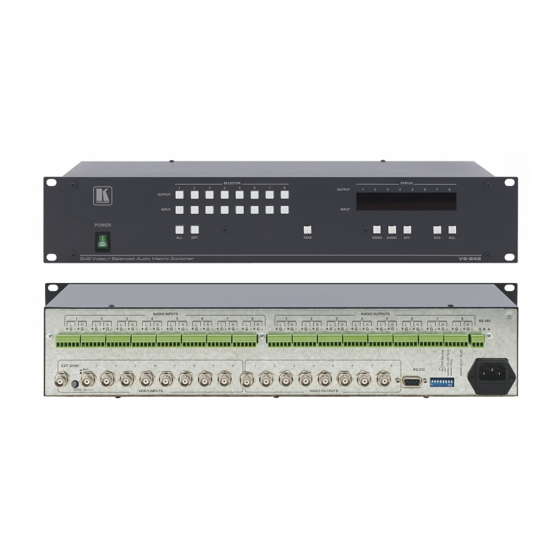
200MHz ensures that the VS-606xl and VS-646 remain transparent even in the most critical applications Features of the VS-606xl and VS-646 Matrix Switchers Front/Rear panel features of the VS-606xl are shown in Figure 1; and for the VS-646, in Figure 2. The features are described in Table 1 and Table 2. -
Page 8: Vs-606Xl Front/Rear Panel Features
Figure 1: VS-606xl Front/Rear Panel Features Figure 2: VS-646 Front/Rear Panel Features KRAMER ELECTRONICS, LTD. -
Page 9: Vs-606Xl/Vs-646 Front Panel Features
RCL illuminated button Should be pressed, followed by an input or output pushbutton to select a predetermined setup (1-6 available setups for the VS-606xl/VS-646 and 1-8 setups for the VS-808xl/VS-848). For example, press RCL followed by INPUT 4 button to recall Setup#4 from the non-volatile memory. -
Page 10: Installation
Table 2: VS-606xl/VS-646 Rear Panel Features Feature Function 1-6 AUDIO INPUTS Audio inputs used to connect the stereo audio input sources. terminal blocks (VS-646), or RCA connectors (VS- 1-6 AUDIO OUTPUTS Audio outputs used to connect the stereo audio output acceptors. -
Page 11: Connecting To Audio Devices
Operate the acceptors. Using the Front Panel Controls The front panels of Kramer Matrix Switcher are designed to be simple to operate, and accomplish the basic function of selecting an input source and output device. Selecting an Output 9.2.1 Output selection on the Matrix Switchers is made by pressing any of the buttons marked “1”... -
Page 12: Storing A Configuration
In the case of interconnection between more than two RS-485 receivers-transmitters (including PC), the termination resistor must be disconnected on all the devices, except the first and last machines on the communication line. DIP switch#4 connects or disconnects the termination resistor. KRAMER ELECTRONICS, LTD. -
Page 13: Rs-232 And Rs-485 Operation
If five machines and a PC are cascaded together for example, using RS-485 interconnection, disconnect the termination resistors on all machines except the fifth (see Figure 6). For similar setup, without a PC connected on the RS-485 line, disconnect all resistors except for the first and fifth machines. KRAMER ELECTRONICS, LTD. -
Page 14: The Pc Control Software
To install the Control Software perform the following steps: Insert the program diskette #1 into the floppy drive of your PC. Run from within Windows95/98 ® the Setup.exe file on the first diskette and follow the instructions. KRAMER ELECTRONICS, LTD. -
Page 15: Software Controls
NOTE When modification of both video and audio crosspoints had been performed, the relevant crosspoints button turn half red/half yellow. AFV button When clicked, selects the "Audio Follow Video" mode to enable AFV setting modification. Breakaway button KRAMER ELECTRONICS, LTD. - Page 16 When clicked, a sub-menu of setups list appears and the user selects the required setup number from the list. The current status is then stored in the non-volatile memory of the switcher. (1-6 available setups for the VS-606xl/VS-646 and 1-8 available setups for the VS-808xl/VS-848). RCL button When clicked, a sub-menu of setups list appears, and the user selects a predetermined setup from the list and then prompted whether he wants to load the current setup.
-
Page 17: Using The Pc Control Software
Using the PC Control Software 9.5.3 Included with your switcher is a CD-ROM with software and drivers for several Kramer products. After installing the K-Switch program perform the following steps: Connect your Matrix Switcher to an identified serial port of the PC. -
Page 18: Typical Applications
Connect all video-audio acceptors to the video-audio outputs of the Matrix Switcher. Operate the Matrix Switcher, PC sources and acceptors. Select the required video input to be switched, using front panel input selector pushbuttons (or the K- Switch program controls). KRAMER ELECTRONICS, LTD. -
Page 19: Component Switching Using Multiple Matrix Switchers
Since RS-232 can only be used for control between 2 pieces of equipment (e.g. a PC and a switcher), we need a method of “distributing” the RS-232 to all 3 machines. The Kramer VP-14 “RS-232 Port Extender” is designed for this purpose. -
Page 20: Rgb/Yuv Switching With Rs-485 Control (Or No Control)
Operate the Matrix Switchers, controller (if used), RGB sources and RGB acceptors. The inputs can now be switched to the outputs. This is done via the front panel switches of the first switcher, and/or via the external controller. KRAMER ELECTRONICS, LTD. -
Page 21: Taking Care Of Your Matrix Switcher
Matrix Switcher. Do not clean your Matrix Switcher with abrasives or strong cleaners. Doing so may remove or damage the finish, or may allow moisture to build up. Take care not to allow dust or particles to build up inside unused or open connectors. KRAMER ELECTRONICS, LTD. -
Page 22: Troubleshooting
If not, turn the power switch off and on again to reset the machine. If the recommended actions still do not result in satisfactory operation, please consult your KRAMER Dealer. Power And Indicators Problem Remedy No power Confirm that the rocker switch is in the “ON”... -
Page 23: Audio Signal
Confirm that the connecting cables are of high quality and properly built. Take special care in noting the wiring configuration of balanced to unbalanced cables. Check level controls located on your source input device or output display or recorder. KRAMER ELECTRONICS, LTD. -
Page 24: Control
COMMUNICATION PROTOCOL Communication with the Matrix Switchers described in this manual uses four bytes of information as defined below. Data is transferred at 9600 baud with no parity, 8 data bits and 1 stop bit. byte DESTINATION INSTRUCTION KRAMER ELECTRONICS, LTD. - Page 25 Set equal to audio input to be Set equal to audio output to be switched switched (0=to all the outputs) STORE STATUS Set as SETUP #(1-8) or (1-6 for - To store parameters the VS-606 , VS-646) - to delete setup KRAMER ELECTRONICS, LTD.
- Page 26 PC, then the switcher (machine#3) will switch input 5 to output 8. If the user switched input#1 to output#7 via the front panel keypad, then the switcher will send: 0100 0001 1000 0001 1000 0111 1000 0011 to the PC. KRAMER ELECTRONICS, LTD.
- Page 27 OUTPUT representing the number after it. For example, for version 3.5, the reply would be: 0111 1101 1000 0011 (i.e. 128 + 3) 1000 0101 (i.e. 128 + 5) 1000 0001 KRAMER ELECTRONICS, LTD.
- Page 28 The table below shows the “HEX” codes for switching the master VS-808xl or VS-848. The table is also valid for the VS-606xl and VS-646 if the last two rows and columns are ignored. OUT 1 OUT 2 OUT 3 OUT 4 OUT 5 OUT 6 OUT 7 OUT 8...
-
Page 29: Limited Warranty
Any product which is not distributed by Kramer or which is not purchased from an authorized Kramer dealer. If you are uncertain as to whether a dealer is authorized, please contact Kramer at one of the agents listed in the web site www.kramerelectronics.com. - Page 30 EXCLUSION OF DAMAGES Kramer’ s liability for any defective products is limited to the repair or replacement of the product at our option. Kramer shall not be liable for: Damage to other property caused by defects in this product, damages based upon inconvenience, loss of use of the product, loss of time, commercial loss;...
- Page 31 For the latest information on our products and a list of Kramer distributors, visit our Web site: www.kramerelectronics.com. Updates to this user manual may be found at http://www.kramerelectronics.com/manuals.html. We welcome your questions, comments and feedback. Kramer Electronics, Ltd. Web site: www.kramerelectronics.com E-mail: info@kramerel.com...
Need help?
Do you have a question about the VS-606xl and is the answer not in the manual?
Questions and answers